

Page 1
WHITE KNIGHT
Air Vented Dryer - UK
0312 427 15301 - 427SV
SERVICE MANUAL
Wiring Diagram
Exploded Views
Parts List
October 2011
0312 427 15311 - 427SVNC
Page 2
369
394
196
386
385
248
370
376
199
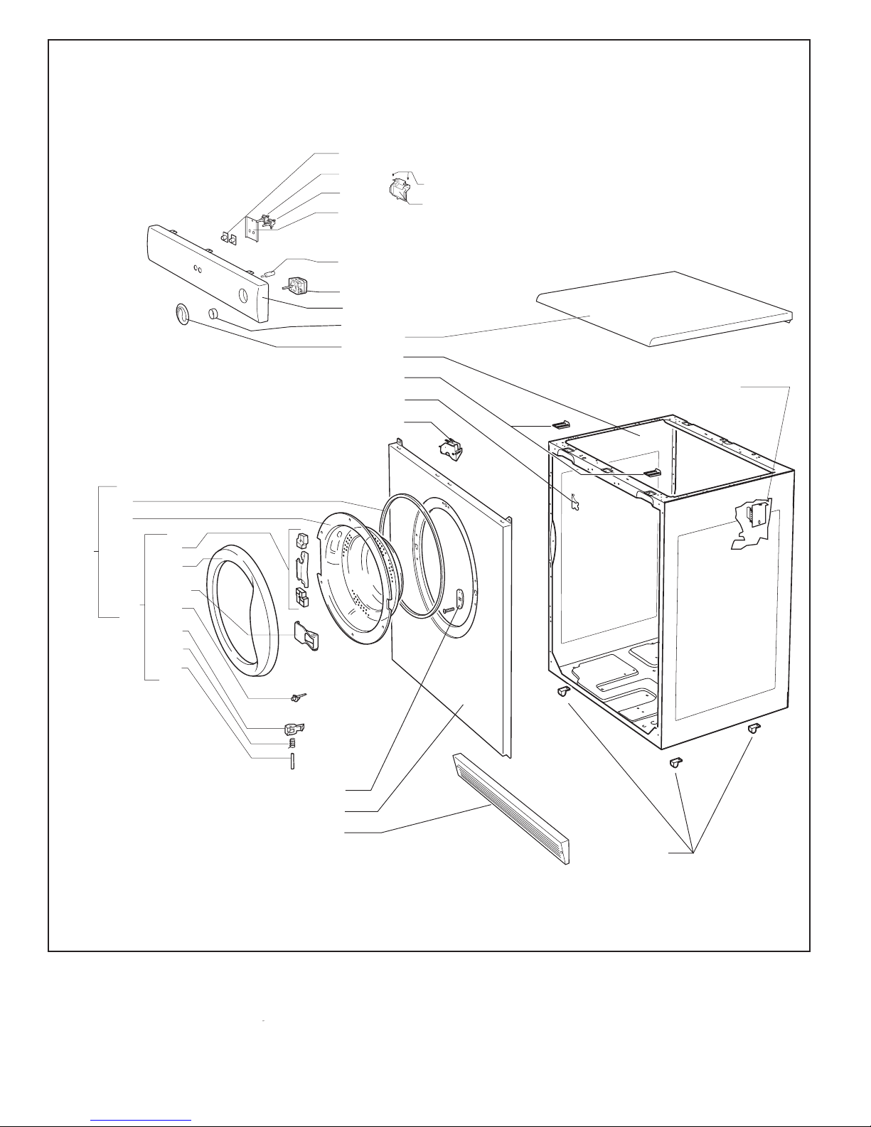
White Knight Air Vented Dryer - Exploded View 1
353
211
352
235
391
556
235a
552
554
248a
366
365
364
363a
363
203a
359
367
362
201
203
497
537
Page 3
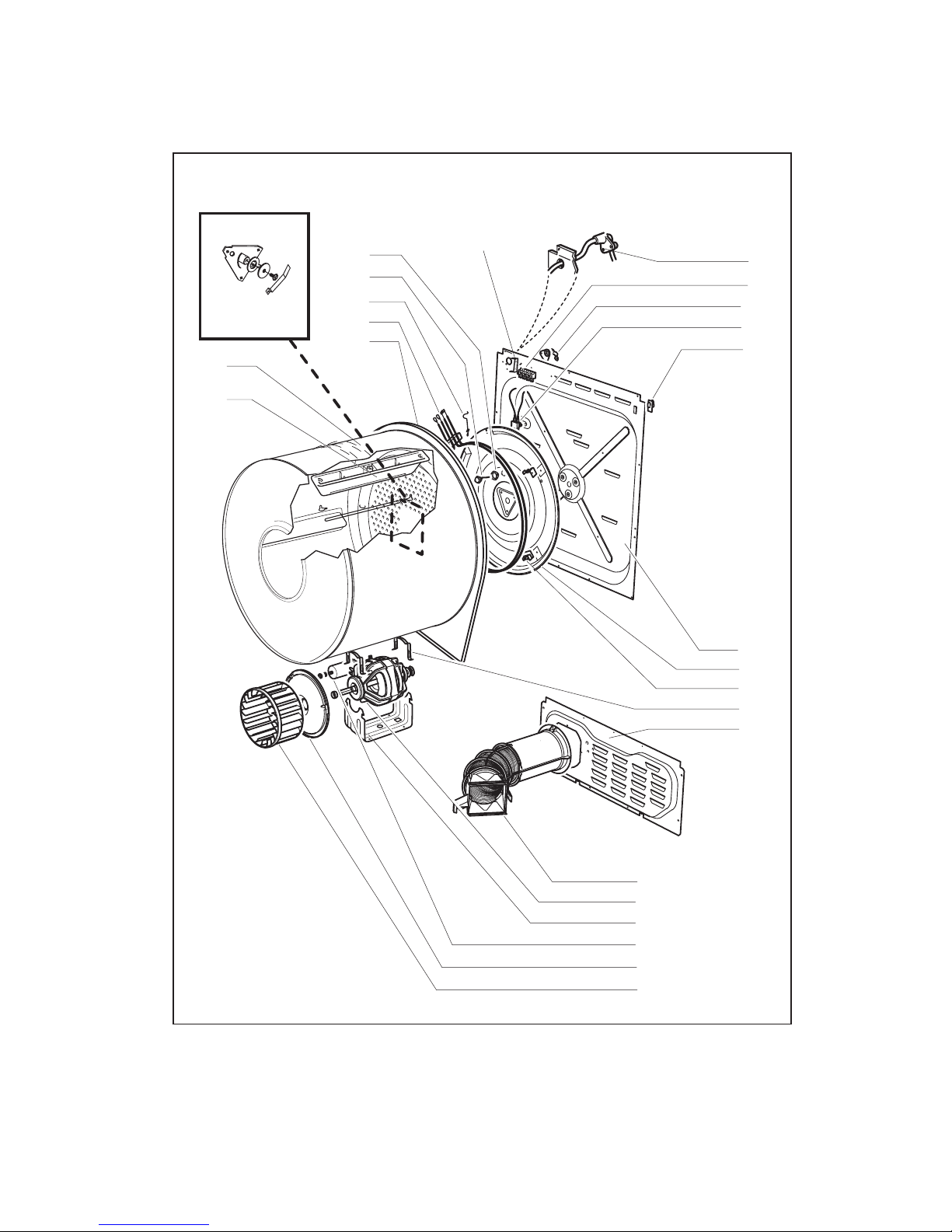
White Knight Air Vented Dryer - Exploded View 2
446
112
447
432
101
437
402
427
399
400
413
230
390
395
227
125
142
408
228
393
270
141
444
266
144
Page 4

144
446
112
447
432
101
402
427
399
400
413
230a
390a
395
227
125
142
408
393
White Knight Air Vented Tumble Dryer - Exploded View 2a
270
141
444
266
437
228a
Page 5

White Knight Air Vented Dryer- Exploded View 3
440
441
442
248
454
437
445
446
447
229
445a
456
458
459
448
Page 6

Wire Colour Code
A
B
C
D
E
F
G
H
K
N/A
-
-
-
-
-
-
-
-
-
-
Black
Brown
Red
Orange
Yellow
Green
Blue
Violet
White
Pink
TB
DS
M
EX-TH
IN-TH
HE
HE-SW
MAN TOC
TM
CAP
-
-
-
-
-
-
-
-
-
-
Terminal Block
Door Switch
Motor
Exhaust Thermostat
Inlet Thermostat
Heater
Heat Switch
Manual Resest Heater Cut-out
Timer
Capacitor
Component Code
Mains
Cable
G
TB-N
G
TB-L
B
F/E
B/K
1.5
F/E
1.25
DS
B/K
1.5
TM
LM
M
H
D
A/K
1.5
M
N
G
G
A
M
B
E
CAP
EX-TH
A/K
A*
IN-TH
A*
HE-SW
G*
1.0
C
0.75
A
0.75
1.5
1.5
TB-4
1.5
HE1
HE2
G*
1.0
MAN
TOC
Wiring Diagram 1
Page 7

Wiring Diagram 2
Page 8

WiringDiagram3
Page 9

White Knight - Parts List
Item Description Code Expl.View
101 Motor & 8µf Capacitor Assembly 4213 092 25611 2
112 8µf Capacitor 4213 092 08091 2
125 Drive Belt 4213 092 18601 2
141 Mains Cable & Plug 4213 076 35123 2
142 Terminal Block 4213 078 44613 2
144 Earth Tab Assembly 4213 092 41181 2
196 Cabinet Assembly 4213 092 36261 1
199 Plinth Assembly 4213 092 38091 1
201 Door Seal 4213 077 08344 1
203 Chrome Full Door Assembly - 427SV 4213 092 36281 1
203 Silver Full Door Assembly - 427SVNC 4213 092 38201 1
203a Chrome Door Frame Assembly - 427SV 4213 092 36091 1
203a Silver Door Frame Assembly - 427SVNC 4213 092 38211 1
211 Timer - wiring 1 4213 078 54771 1
211 Timer - wirng 2 4213 078 57341 1
227 Heating Element 4213 092 05521 2
228 Heat TOC 4213 078 50161 2
228a Heat TOC 4213 078 57371 2a
229 Thermostat 4213 078 48373 3
230 Thermostat (inlet) 4213 078 56261 2
230a Thermostat (inlet) 4213 078 57361 2a
235 Heat Switch 4213 078 52811 1
235a Start Switch 4213 078 52821 1
248 Microswitch/Bracket Assembly 4213 092 05251 1 & 3
248a Door Interlock Relay Board 4213 092 48771 1
266 Drum Assembly 4213 092 05531 2
270 Drum Shaft/Bearing Kit 4213 092 05591 2
352 Timer Knob Assembly 4213 092 36251 1
353 Control Panel Assembly - 427SV 4213 092 49311 1
353 Control Panel Assembly - 427SVNC 4213 092 49321 1
359 Door Hinge Assembly 4213 092 25361 1
362 Window 4213 077 44095 1
363 Chrome Door Frame - 427SV 4213 077 82721 1
363 Silver Door Frame - 427SVNC 4213 077 84071 1
363a Door Handle 4213 077 82861 1
364 Latch Pivot 4213 075 13013 1
365 Latch Spring 4213 075 70833 1
366 Door Latch 4213 077 53413 1
367 Switch Strike 4213 077 83571 1
369 Loom Clip 4213 075 70941 1
370 Latch Guide 4213 077 40992 1
376 Front Panel Assembly 4213 092 36301 1
PLEASE NOTE bold text indicates choice of parts depending on model colour. 0312 427 15301 15311
Page 10

White Knight - Parts List
385 Top Cover Bracket 4213 070 14541 1
386 Top Cover Assembly 4213 092 36141 1
390 Gasket 4213 074 50862 2
390a Gasket 4213 092 45121 2a
391 Chrome Button 4213 077 82781 1
393 Flex Support Clip 4213 077 40982 2
394 Foot 4213 077 39833 1
395 Heater Wires Clip 4213 075 70971 2
399 Heater Support 4213 080 06619 2
400 Heater Plate 4213 080 14551 2
402 Access Panel 4213 080 06558 2
408 Cable Clamp 4213 077 47303 2
413 Back Panel 4213 092 37601 2
427 Motor Spring Clip 4213 078 45362 2
432 Motor Mount Bracket 4213 080 0675A 2
437 Vent Hose Assembly 0312 002 01000 2 & 3
440 Banjo Assembly 4213 092 17811 3
441 Front Bearing (short) 4213 077 40952 3
442 Front Seal 4213 077 40942 3
444 Lifter 4213 077 41009 2
445 Front Bearing (long) 4213 077 40962 3
445a Bearings & Brush Seal Kit Assy 4213 092 21171 3
446 Fan 4213 077 40896 2 & 3
447 Access Cover Assembly 4213 092 18081 2 & 3
448 Spring Clip (Fan) 4213 075 71162 3
454 Filter 4213 092 17821 3
456 Banjo Seal 4213 077 07991 3
458 Banjo Insert No 2 4213 077 53502 3
459 Banjo Insert No 1 4213 077 53492 3
497 Switch Cover 4213 177 01141 1
552 Timer Extension 4213 077 92121 1
552 Timer Extension /22 only 4213 077 59953 1
554 Timer Shaft Support 4213 077 60081 1
554 Timer Shaft Support /22 only 4213 075 15061 1
556 Switch Bracket 4213 070 11692 1
537 W' Button Plug 4213 078 26311 1
Not shown on exploded views
INSTRUCTION BOOK - EXP VIEW 2 4213 094 5932C
INSTRUCTION BOOK - EXP VIEW 2a 4213 094 66581
PLEASE NOTE bold text indicates choice of parts depending on model colour. 0312 427 15301 15311
Page 11

White Knight - Parts List
We are in the process of developing a new Heat TOC and Inlet thermostat design
to avoid nuisance operations. Tumble dryers with the following serial numbers have
been fiited with the improved combination of thermostats, and have had removed
the black open-bladed Heat TOC ( see - exploded view 2, item 288 ) and Inlet
thermostat (see - exploded view 2, item 230).
Machine 0312 427 15301
To identify these machines, they will have serial numbers From 0838 232381 to 0838 232480
Machine 0312 427 15311
To identify these machines, they will have serial numbers From 0838 233878 to 0838 234177
From 0839 242822 to 0839 243221
The improved design uses both a new Inlet thermostat and heat TOC combination.
These must be used as a pair and is not to be swapped with exsisting parts, or used
on dryers with the black open-bladed Heat TOC ( see exploded view 2a, item 228a)
please order the correct new parts indicated by bold text in the parts list.
If the Heat TOC has tripped and needs to be reset, it can only be reset from inside
the dryer, by removing the backpanel and depressing the small red button on the
rear of the Heat TOC. If the Heat TOC has tripped, the most likely reason is that the
Inlet thermostat has failed and must be replaced. Nuisance operation is most
unlikely, always look for a cause.
Timer changes & changes to the loom wiring
If your dryer does not have a /22 on the rating plate (on rear of dryer), it will use
wirng diagram 1 and timer 4213 078 54771
If your dryer has a /22 on the rating plate (on rear of dryer), it will use
wirng diagram 2 and timer 4213 078 57341
If the serial number on your dryer starts with 1003 or higher, it will use
wiring diagram 3 and timer 4213 078 57341
PLEASE NOTE bold text indicates choice of parts depending on model colour. 0312 427 15301 15311
 Loading...