

Whitehall Products E-27-S User Manual

E-27-S
S-90-S
STATIONARY WHIRLPOOL
OPERATION AND MAINTENANCE MANUAL
6900-194-000 Revised: November 2012
PLEASE READ THIS ENTIRE
European Union CE Mark
WARNING
To avoid electric shock, connect the instrument to properly earth-grounded, GFC I protected, 3-prong
receptacles only. Failure to observe this precaution can result in severe injury.
BOOKLET BEFORE OPERATING
! !
YOUR NEW WHIRLPOOL
Failure to follow these instructions could result in damage
to your new whirlpool and/or bodily injury
The presence of the CE Mark on Whitehall equipment means that it has been designed, tested and certified as complying
with all applicable European Union regulati ons and recommendations.
Waste Electrical and Electronic Equipment (WEEE)
This symbol on the product or on its packaging indicates that this product must not be disposed of w ith regular waste.
Instead, it is the user’s responsibil ity to dispose of waste equipment according to the local laws. Separate collection and
recyc ling of the waste equipment at the time of disposal will help conserve natural resources and ensure it is recycled in a
manner that protects human health and the environment. For information about where the user can drop off the waste
equipment for recycling, please contact your local waste collection authority. See Page 30 for instructions on how to
disassemble the equipment for recyc ling purposes.
General Warning or Caution
The Exclamation Sym bol appears in W arning and Caution statements. This symbol designates where personal injury or
damage to the equipment is possible.
Electric Shock
The Electric Shock Sym bol is used to indicate a hazard ari sing from dangerous voltage. Any mishandling could result in
irreparable damage to the equipment and/or personal injur y or death.
Ÿ WHIRLPOOLS intended for professional use only.
Ÿ 220v WHIRLPOOLS for export only.
Ÿ DO NOT operate appliance without properly filling with water. Under no conditions should the appliance be operated
without water. Fill appliance with water to the prescribed level before plugging into an electrical receptacle. Operating the
appliance without water may result in damage to the motor.
Ÿ IMPROPER USE of the whirlpool can cause injury. Use the whirlpool only for the purpose described in this manual.
Ÿ THE TURBINE is top-heavy. Improper handling can cause injury or damage. Handle the turbine with care.
Ÿ ATTACHING IMPROPER items to the whirlpool can cause injury to persons and damage to equipment. Use only Whitehall
approved items on the whirlpools.
Ÿ INCORRECT PARTS and service can cause injury to persons and damage equipment. Use only Whitehall parts and
Whitehall approved service on whirlpools.
3
3
a
WHITEHALL MANUFACTURING • P.O. Box 3527 • City of Industry, CA 91744-0527 U.S.A.
Phone (800) 782-7706 • (626) 968-6681 • Fax (626) 855-4862 • Web: www.whitehallmfg.com

Table of Contents
Warning ................................................................................................................................................Page a
Table of Contents .................................................................................................................................Page 1
General Knowledge..............................................................................................................................Page 2
Operating Skills & Training..........................................................................................................Page 2
Patient Evaluation .......................................................................................................................Page 2
Inspecting Whirlpool ....................................................................................................................Page 2
Using The Whirlpool .............................................................................................................................Page 3
Installation & Operation ...................................................................................................................Pages 4-7
Fixture Installation Location Guide..............................................................................................Page 4
Combined Drain / Overflow .........................................................................................................Page 5
Separate Drain / Overflow...........................................................................................................Page 6
Slant Back ...................................................................................................................................Page 7
Repair Parts .................................................................................................................................Pages 8-26
Stationary Motor/Turbine Assembly.............................................................................................Page 8
Stationary "E" Series ...................................................................................................................Page 9
Stationary "H" Series .................................................................................................................Page 10
Stationary "L" Series..................................................................................................................Page 11
Stationary "P" Series .................................................................................................................Page 12
Stationary "S" Series .................................................................................................................Page 13
Motor Raising & Lowering Assembly (Small).............................................................................Page 14
Motor Raising & Lowering Assembly ........................................................................................Page 15
Motor Raising & Lowering Assembly (Slant Back) ....................................................................Page 16
Drain / Overflow Assembly - H/S Series....................................................................................Page 17
Drain / Overflow Assembly - "E" Series.....................................................................................Page 18
Drain / Overflow Assembly - (Lo-Boy) .......................................................................................Page 19
Drain / Overflow Assembly - Podiatry Series.............................................................................Page 20
Drain / Overflow Assembly - Slant Back....................................................................................Page 21
Separate Drain / Overflow Assembly - P-10, P/E-15/22............................................................Page 22
Separate Drain / Overflow Assembly - E-22-SP, E-27/45 ..........................................................Page 23
Separate Drain / Overflow Assembly - H-60/70/90, S-85/90 .....................................................Page 24
Butterfly Drain Valve ..................................................................................................................Page 25
Thermometers ...........................................................................................................................Page 26
Cleaning & Disinfecting ....................................................................................................................Pages 27
Care & Cleaning ...............................................................................................................................Pages 28
Maintenance & Troubleshooting.......................................................................................................Pages 29
Motor Information .............................................................................................................................Pages 29
WHITEHALL MANUFACTURING • P.O. Box 3527 • City of Industry, CA 91744-0527 U.S.A.
Phone (800) 782-7706 • (626) 968-6681 • Fax (626) 855-4862 • Web: www.whitehallmfg.com
1

General Knowledge
OPERATOR SKILLS AND TRAINING
Skills:
Operators using the whirlpool need:
Ÿ a working knowledge of aquatic physical-therapy
procedures.
Ÿ the ability to assist the patient.
!
!
WARNING
WARNING
Untrained operators can cause injury or be injured.
Permit only trained personnel should operate the
whirlpool.
PATIENT EVALUATION
Require Each Patient To Be Evaluated
Patients who are electrically-susceptible (patients with
exposed, non-waterproof electric leads, monitors, etc.),
patients carrying infectious disease,
certain other medical, mental or physical conditions should
not receive treatment with the whirlpool.
The trained operator must evaluate and verify that each
patient is suitable for hydrotherapy treatment before
permitting the patient to begin hydrotherapy. If in doubt,
co nsul t a m edical pr ofessional before prov iding
hydrotherapy treatment.
or patients with
TRAINING
Operator trainees need to:
Ÿ be trained in aquatic-therapy protocols.
Ÿ be familiar with the types of patients who should or
should not receive this type of physical therapy (see
Patient Evaluation, below).
Ÿ read and understand this manual (and the manual for
the turbine, if used).
Ÿ be trained on the use of the whirlpool (and turbine, if
used).
Ÿ practice with the whirlpool (and turbine, if used) before
use with patient.
!
!
WARNING
WARNING
Certain medical conditions are incompatible with
hydrotherapy. The trained operator is responsible for
determining each user’s suitability for hydrotherapy
before beginning treatment.
Important
BLOODBORNE DISEASE NOTICE: To reduce the
risk of exposure to bloodborne diseases such as HIV-1
and hepatitis when using the whirlpool, read and
follow the disinfecting and cleaning instructions in this
manual thoroughly.
INSPECTING THE WHIRLPOOL
This Whitehall product has been carefully packaged at the
factory to minimize the possibility of damage during
shipping.
— Inspect the packaging for external signs of damage.
— Inspect the contents for damage.
If there is visible damage to the instrument upon receipt,
inform the shipping company and Whitehall immediately.
!
!
WARNING
WARNING
Do not attempt to operate this equipment if there is
evidence of shipping damage or you suspect the unit
is damaged. Damaged equipment may present
additional hazards to you. Contact Whitehall technical
support for advice before attempting to plug in and
operate damaged equipment.
Have your facility's equipment maintenance personnel
inspect the whirlpool regularly. Follow the checklist at right
and operate the whirlpool through all its functions as
described in this manual.
2
WHITEHALL MANUFACTURING • P.O. Box 3527 • City of Industry, CA 91744-0527 U.S.A.
Phone (800) 782-7706 • (626) 968-6681 • Fax (626) 855-4862 • Web: www.whitehallmfg.com
Inspection Checklist
Ÿ
Are all components present?
Ÿ
Is the whirlpool free of excessive wear?
Ÿ
Does the turbine mount securely in place?
Ÿ
Is a properly-grounded and voltage-matched
hospital grade receptacle available for the turbine?
Ÿ
Is the outlet or turbine cord equipped with a
functioning GFI (or RCD)?
Ÿ
Can the turbine be raised, lowered and locked at the
desired height?
Ÿ
Does the drain valve open and close properly?
Ÿ
Is the thermometer present and is it legible?
Ÿ
Do the installed accessories operate without
interfering with whirlpool use or turbine operation?

USING THE WHIRLPOOL
Before Placing the Whirlpool In Service:
Operators using the whirlpool need:
Ÿ Personnel who will work with the whirlpool need to read
this manual.
Ÿ Have a plumbing professional install the whirlpool as
instructed in page 4. A rough-in
drawing is available to assist the installer. Contact
Whitehall Customer Service, bottom of page, for
additional installation not covered in this manual.
Ÿ Confirm that the whirlpool operates properly. See
Inspecting the Whirlpool , page 2.
Installing the Whirlpool,
Using The Whirlpool
General Guidelines for Use:
Ÿ Medical advice is beyond the parameters of this
manual.
Ÿ The whirlpool is for professional use only. A minimum of
one trained operator is required.
Ÿ The trained operator must evaluate and verify that the
patient is suitable for hydrotherapy treatment before
beginning hydrotherapy with whirlpool. See Patient
Evaluation, page 2.
Ÿ Follow your state and local hydrotherapy procedures
and, if the patient has one, the physician's order for
treatment (see Patient Evaluation, page 2).
Ÿ Stay with patient at all times.
Ÿ It is the operators responsibility to ensure safe practices
for the patient and themselves.
Ÿ If a turbine is used:
Plug the turbine cord only into a receptacle that is voltagematched, properly grounded and polarized. Verify that the
receptacle has GFI protection or order a GFCI plug for the
turbine cord.
Keep patient hair, gown strings and other loose items
away from the impeller housing to avoid entanglement
and injury.
Keep the area around the turbine clear. The turbine
requires a minimum of 24" (610mm) of clearance.
!
WARNING
Certain medical conditions are incompatible with
hydrotherapy. The trained operator is responsible for
determining each user's suitability for hydrotherapy
before beginning treatment.
Improper operation can cause injury. Operate the
whirlpool only as described in this manual.
An unattended patient can be injured. Stay with
patient at all times.
Loose items such as gown straps or gauze can be
pulled into the turbine impeller and cause injury. Keep
loose items away from the turbine impeller housing.
Important
Communicate with patient at all times. If a turbine is
used, tell the patient before starting or stopping the
turbine and before changing the water or aeration
level.
WHITEHALL MANUFACTURING • P.O. Box 3527 • City of Industry, CA 91744-0527 U.S.A.
Phone (800) 782-7706 • (626) 968-6681 • Fax (626) 855-4862 • Web: www.whitehallmfg.com
3
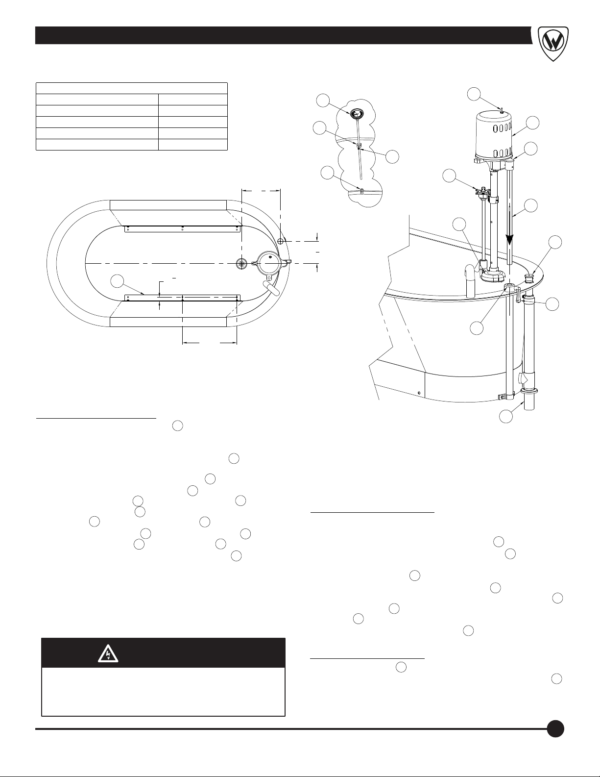
Fixture Installation Location Guide
DIMENSION DESCRIPTION
"A"
DISTANCE FOR:
MXT2 (MV2) 3/4" NPT
VALVE = 9-1/2"
MXT1 (MV1) 1/2" NPT
VALVE = 8-1/2"
"B"
DISTANCE FOR:
MXT2 (MV2) 3/4" NPT
VALVE = 13-1/2"
MXT1 (MV1) 1/2" NPT
VALVE = 13-3/4"
2
3
4
"
4
(120)
"B"
12"
(305)
REC. MIN.
12"
(305)
REC. MIN.
"A"
3
7
"B"
6
1
52
"
4
(1327)
9
ELECTRICAL REQUIREMENTS: 8 AMPS, 115 VOLTS. AT
1
WALL PROVIDE ONE 3 POLE RECEPTACLE HOSPITAL
GRADE WITH GROUND FAULT INTERRUPT FOR TURBINE
ASSEMBLY
THERMOSTATIC MIXING VALVES ARE OPTIONAL
2
OPTIONAL -MXWH (HA-WASHOUT ASSEMBLY)
3
2" x 5" TAIL PIECE FURNISHED WITH UNIT
4
5
1
8
2" COMBINATION DRAIN AND OVERFLOW ASSEMBLY
5
FURNISHED BY WHITEHALL
OVER RIM INLET
6
HOT & COLD WATER INLET
7
2" DRAIN
8
'L'-CLIPS FOR FLOOR MOUNTING
9
4
1
52
4
(1327)
"
4
WHITEHALL MANUFACTURING • P.O. Box 3527 • City of Industry, CA 91744-0527 U.S.A.
Phone (800) 782-7706 • (626) 968-6681 • Fax (626) 855-4862 • Web: www.whitehallmfg.com
NOTE: THESE INSTALLATION
INSTRUCTIONS ARE USED FOR
ALL WHITEHALL OR DAKON
STATIONARY ALL MODELS.
REFERENCE DRAWINGS
ASSEMBLIES
MOTOR/TURBINE 8
RAISING/LOWERING/SM
RAISING/LOWERING 15
DRAIN OVERFLOW E
DRAIN OVERFLOW H/S
DRAIN OVERFLOW - L
THERMOMETER 26
PAGE NUMBER
14
18
17
19
20DRAIN OVERFLOW - P
3
"
4
2
1"
C
L
DETAIL "A"
(TOP VIEW)
7
Installation Instructions
13
1
5"
1
2
"
4
11
12
3
14
6
15
ASSEMBLY PROCEDURE:
A-
ROUGH-IN FOR 2" OD DRAIN LINE 1 AND WATER INLET VALVE.
(SEE DETAIL A) NOTE: FOR INFORMATION ON OPTIONAL
THERMOSTATIC MIXING VALVE CONTACT FACTORY.
B-
LOCATE TANK AND SECURE WITH "L" BRACKETS 2 , WITH
INSTALLER PROVIDED FLOOR ANCHORS AND ANCHORING
HARDWARE. MAKE WASTE CONNECTIONS 1 .
C-
INSTALL MOTOR/TURBINE ASSEMBLY 3 INTO RAISING AND
LOWERING ASSEMBLY 4 BY LOOSENING HANDLE 5 , SLIDING
MOTOR SUPPORT ROD 6 INTO RAISING AND LOWERING
ASSEMBLY 4 AND TIGHTENING HANDLE 5 .
D-
INSTALL THERMOMETER 7 THRU UPPER BRACKET 8 AND
INTO LOWER BRACKET 9 , TIGHTEN SCREW 10 .
E-
TURN THE PRESSURE CONTROL VALVE HANDLE 11 FULLY
CLOCKWISE, THEN FULLY COUNTERCLOCKWISE TO
COMPLETELY LUBRICATE THE PLUNGER ASSEMBLY.
F-
PROVIDE ELECTRICAL SERVICE AND PROPERLY INSTALLED,
GROUND FAULT CIRCUIT INTERRUPTER (GFCI) FOR MOTOR
SPECIFIED. MOTOR SPECIFICATIONS AVAILABLE ARE EITHER
120V AC / 60 HZ ON 15A CIRCUIT OR 240 V AC / 50 HZ ON 10A
WARNING
WARNING
Turbine assembly is provided with a 3-way plug. The
third prong functions as a built-in ground and must be
plugged into a matching grounded receptacle to
properly ground the product.
8
10
4
5
9
1
OPERATION PROCEDURE:
A-
FILL TUB AS DESIRED USING THERMOSTATIC MIXING VALVE.
WATER LEVEL SHOULD BE A MAXIMUM OF 4" BELOW THE RIM
AND A MINIMUM OF 6" ABOVE BOTTOM PUMP 12 .
B-
TURN THE PRESSURE CONTROL VALVE HANDLE 11 FULLY
CLOCKWISE, THIS PROVIDES MAX PRESSURE AND AGITATION.
C-
TURN ON THE SWITCH 13 .
D-
ADJUST RAISING AND LOWERING ASSEMBLY 4 BY SLOWLY
PUSHING DOWN ON TOP OF THE MOTOR SUPPORT CASTING 14
UNTIL THE PUMP 12 IS AT THE DESIRED LOCATION. TIGHTEN
HANDLE 5 . INTERNAL BUSHING MAY NEED ADJUSTMENT.
E-
ADJUST PRESSURE CONTROL VALVE 11 TO DELIVER DESIRED
LEVEL OF AGITATION AND PRESSURE.
DRAINING PROCEDURE:
A-
TURN OFF SWITCH 13 .
B-
LIFT COMBINATION DRAIN & OVERFLOW ASSEMBLY HANDLE 15 .
WHITEHALL MANUFACTURING • P.O. Box 3527 • City of Industry, CA 91744-0527 U.S.A.
Phone (800) 782-7706 • (626) 968-6681 • Fax (626) 855-4862 • Web: www.whitehallmfg.com
5
Installation Instructions; -SDO Separate Drain Overflow
NOTE: THESE INSTALLATION
INSTRUCTIONS ARE USED FOR
ALL WHITEHALL OR DAKON
ALL STATIONARY -SDO MODELS.
REFERENCE DRAWINGS
ASSEMBLIES
MOTOR/TURBINE 8
RAISING/LOWERING/SM
RAISING/LOWERING 15
DRAIN OVERFLOW E
DRAIN OVERFLOW H/S
THERMOMETER
PAGE NUMBER
14
23
24
22DRAIN OVERFLOW - P
26
8
10
3
"
4
1"
13
3
2
14
C
L
7
7
"
8
1
3
"
2
1
11
6
DETAIL "A"
(TOP VIEW)
7
12
4
15
5
9
ASSEMBLY PROCEDURE:
A-
ROUGH-IN FOR 2" OD DRAIN LINE 1 AND WATER INLET VALVE.
(SEE DETAIL A) NOTE: FOR INFORMATION ON OPTIONAL
THERMOSTATIC MIXING VALVE CONTACT FACTORY.
B-
LOCATE TANK AND SECURE WITH "L" BRACKETS 2 , WITH
INSTALLER PROVIDED FLOOR ANCHORS AND ANCHORING
HARDWARE. MAKE WASTE CONNECTIONS 1 .
C-
INSTALL MOTOR/TURBINE ASSEMBLY 3 INTO RAISING AND
LOWERING ASSEMBLY 4 BY LOOSENING HANDLE 5 , SLIDING
MOTOR SUPPORT ROD 6 INTO RAISING AND LOWERING
ASSEMBLY 4 AND TIGHTENING HANDLE 5 .
D-
INSTALL THERMOMETER 7 THRU UPPER BRACKET 8 AND
INTO LOWER BRACKET 9 , TIGHTEN SCREW 10 .
E-
TURN THE PRESSURE CONTROL VALVE HANDLE 11 FULLY
CLOCKWISE, THEN FULLY COUNTERCLOCKWISE TO
COMPLETELY LUBRICATE THE PLUNGER ASSEMBLY.
F-
PROVIDE ELECTRICAL SERVICE AND PROPERLY INSTALLED,
GROUND FAULT CIRCUIT INTERRUPTER (GFCI) FOR MOTOR
SPECIFIED. MOTOR SPECIFICATIONS AVAILABLE ARE EITHER
120V AC / 60 HZ ON 15A CIRCUIT OR 240 V AC / 50 HZ ON 10A
WARNING
WARNING
Turbine assembly is provided with a 3-way plug. The
third prong functions as a built-in ground and must be
plugged into a matching grounded receptacle to
properly ground the product.
16
OPERATION PROCEDURE:
A-
FILL TUB AS DESIRED USING THERMOSTATIC MIXING VALVE.
WATER LEVEL SHOULD BE A MAXIMUM OF 4" BELOW THE RIM
AND A MINIMUM OF 6" ABOVE BOTTOM PUMP 12 .
B-
TURN THE PRESSURE CONTROL VALVE HANDLE 11 FULLY
CLOCKWISE, THIS PROVIDES MAX PRESSURE AND AGITATION.
C-
TURN ON THE SWITCH 13 .
D-
ADJUST RAISING AND LOWERING ASSEMBLY 4 BY SLOWLY
PUSHING DOWN ON TOP OF THE MOTOR SUPPORT CASTING 14
UNTIL THE PUMP 12 IS AT THE DESIRED LOCATION. TIGHTEN
HANDLE 5 . INTERNAL BUSHING MAY NEED ADJUSTMENT.
E-
ADJUST PRESSURE CONTROL VALVE 11 TO DELIVER DESIRED
LEVEL OF AGITATION AND PRESSURE.
DRAINING PROCEDURE:
A-
TURN OFF SWITCH 13 .
B-
TURN HANDLE 15 CLOCKWISE TO OPEN DRAIN VALVE 16 .
1
6
WHITEHALL MANUFACTURING • P.O. Box 3527 • City of Industry, CA 91744-0527 U.S.A.
Phone (800) 782-7706 • (626) 968-6681 • Fax (626) 855-4862 • Web: www.whitehallmfg.com
Installation Instructions; Slant Back
REFERENCE DRAWINGS
ASSEMBLIES
MOTOR/TURBINE 8
RAISING/LOWERING
DRAIN OVERFLOW
THERMOMETER
2
PAGE NUMBER
1
1
"
4
TYP.
16
21
26
17"
TYP.
12
DETAIL "A"
(TOP VIEW)
7
8
10
9
1
"
8
7
6
"
8
13
3
14
11
6
12
15
5
4
ASSEMBLY PROCEDURE:
A-
ROUGH-IN FOR 2" OD DRAIN LINE 1 AND WATER INLET VALVE.
(SEE DETAIL A) NOTE: FOR INFORMATION ON OPTIONAL
THERMOSTATIC MIXING VALVE CONTACT FACTORY.
B-
LOCATE TANK AND SECURE WITH "L" BRACKETS 2 , WITH
INSTALLER PROVIDED FLOOR ANCHORS AND ANCHORING
HARDWARE. MAKE WASTE CONNECTIONS 1 .
C-
INSTALL MOTOR/TURBINE ASSEMBLY 3 INTO RAISING AND
LOWERING ASSEMBLY 4 BY LOOSENING HANDLE 5 , SLIDING
MOTOR SUPPORT ROD 6 INTO RAISING AND LOWERING
ASSEMBLY 4 AND TIGHTENING HANDLE 5 .
D-
INSTALL THERMOMETER 7 THRU UPPER BRACKET 8 AND
INTO LOWER BRACKET 9 , TIGHTEN SCREW 10 .
E-
TURN THE PRESSURE CONTROL VALVE HANDLE 11 FULLY
CLOCKWISE, THEN FULLY COUNTERCLOCKWISE TO
COMPLETELY LUBRICATE THE PLUNGER ASSEMBLY.
F-
PROVIDE ELECTRICAL SERVICE AND PROPERLY INSTALLED,
GROUND FAULT CIRCUIT INTERRUPTER (GFCI) FOR MOTOR
SPECIFIED. MOTOR SPECIFICATIONS AVAILABLE ARE EITHER
120V AC / 60 HZ ON 15A CIRCUIT OR 240 V AC / 50 HZ ON 10A
WARNING
WARNING
Turbine assembly is provided with a 3-way plug. The
third prong functions as a built-in ground and must be
plugged into a matching grounded receptacle to
properly ground the product.
1
OPERATION PROCEDURE:
A-
FILL TUB AS DESIRED USING THERMOSTATIC MIXING VALVE.
WATER LEVEL SHOULD BE A MAXIMUM OF 4" BELOW THE RIM
AND A MINIMUM OF 6" ABOVE BOTTOM PUMP 12 .
B-
TURN THE PRESSURE CONTROL VALVE HANDLE 11 FULLY
CLOCKWISE, THIS PROVIDES MAX PRESSURE AND AGITATION.
C-
TURN ON THE SWITCH 13 .
D-
ADJUST RAISING AND LOWERING ASSEMBLY 4 BY SLOWLY
PUSHING DOWN ON TOP OF THE MOTOR SUPPORT CASTING 14
UNTIL THE PUMP 12 IS AT THE DESIRED LOCATION. TIGHTEN
HANDLE 5 . INTERNAL BUSHING MAY NEED ADJUSTMENT.
E-
ADJUST PRESSURE CONTROL VALVE 11 TO DELIVER DESIRED
LEVEL OF AGITATION AND PRESSURE.
DRAINING PROCEDURE:
A-
TURN OFF SWITCH 13 .
B-
LIFT COMBINATION DRAIN & OVERFLOW ASSEMBLY HANDLE 15 .
WHITEHALL MANUFACTURING • P.O. Box 3527 • City of Industry, CA 91744-0527 U.S.A.
Phone (800) 782-7706 • (626) 968-6681 • Fax (626) 855-4862 • Web: www.whitehallmfg.com
7
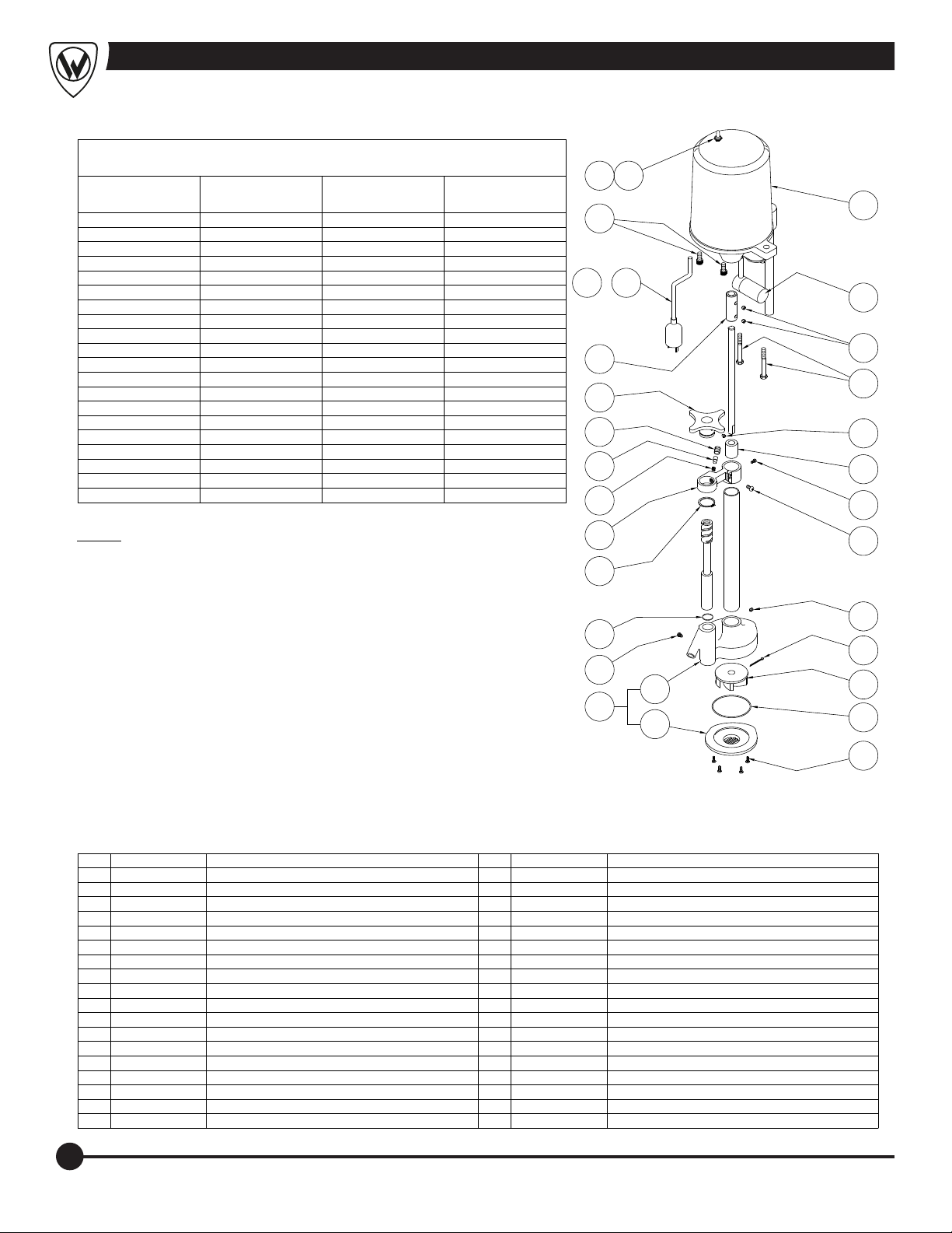
Stationary Motor/Turbine Assembly
THESE REPAIR PARTS ARE USED FOR THE
FOLLOWING MODEL NUMBERS ONLY:
WHITEHALL MODEL
NUMBERS
E-15-M-SDP
E-15-S
E-22-M-SDP
E-22-S
E-22-SP
E-27-M-SDP DD-2821
E-27-S DF-2821
E-36-M-SDP DD-2825
E-36-S DF-2825
E-45-M-SDP
E-45-S
H-60-M-SDP DD-3628
H-60-S
H-75-M-SDP
H-75-S
H-90-M-SDP
H-90-S
H-105-M-SDP DD-4828
H-105-S DF-4828
DAKON
MODEL NUMBERS
DD-2516
DF-2516
DD-2818
DF-2818
DF-3225
DF-3628
WHITEHALL MODEL
NUMBERS
L-75-M-SDP
L-75-S
L-90-M-SDP DD-6018
L-90-S DF-6018
L-90-SL
L-105-M-SDP DD-6618
L-105-S DF-6618
L-105-SL
P-10-S
P-15-M-SDP DD-2516
P-15-S DF-2516
P-22-M-SDP DD-2818
P-22-S DF-2818
S-85-M-SDP
S-85-S
S-90-M-SDP
S-90-S
S-110-M-SDP DDT-5625
S-110-S DFT-5625
SB-100-S
DAKON
MODEL NUMBERS
DDT-4825
DFT-4825
14 15
16
17A - 17H
18
19
20
21
22
13
12
11
10
9
8
7
NOTE: SEE ADDITIONAL DRAWINGS FOR
23
COMPLETE ASSEMBLY NUMBERS AND
DETAIL OF ITEMS NOT LISTED.
STATIONARY ''E'' SERIES
STATIONARY ''SB'' SERIES
Page 9
Page 9
STATIONARY ''H'' SERIES Page 10
STATIONARY ''L'' SERIES
STATIONARY ''P'' SERIES
STATIONARY ''S'' SERIES
Page 11
Page 12
Page 13
24
25
26
28
27
29
ITEM PART NUMBER DESCRIPTION ITEM PART NUMBER DESCRIPTION
1 6502-307-000 #8-32 x 1/2" PHIL FLAT HD SELF TAPPING
2 6504-501-199 17" PUMP GASKET
3 6525-518-000 TURBINE IMPELLER - PLASTIC
4 0341-101-000 COTTER PIN
5 6502-401-000 1/4"-20 x 5/16" HEX SOCKET SET SCREW
6 6502-042-000 1/4"-20 x 5/8" PHIL PAN HEAD SCREW
7 6502-300-000 #8-32 x 3/8" PHIL FLAT HEAD SELF TAPPING
8 6525-514-199 SHAFT BEARING
9 6502-410-000 1/4"-20 x 1/4" DOG SET SCREW
10 6502-352-000 3/8"-16 x 3" HEX CAP SCREW
11 6502-402-000 5/16"-16 x 1/4" HEX SOCKET SET SCREW
12 6502-020-001 CONDENSER ASSEMBLY
13 6525-600-000 PLASTIC MOTOR COVER
14 6505-025-000 DPST TOGGLE SWITCH
15 6505-035-000 WATERPROOF TOGGLE SWITCH CAP
16 6502-452-000 3/8"-16 x 3/4" HEX SOCKET CAP SCREW
17A 6505-030-000 10 FEET, 115VAC, 60Hz POWER CORD
17B 6505-034-001 DOMESTIC POWER CORD 220VAC, 60Hz
17C 6505-044-001 RUSSIAN POWER CORD, 250VAC, 50Hz
17D 6505-074-001 INDIA/S. AFRICA POWER CORD, 230VAC, 50Hz
17E 6505-043-001 EUROPEAN POWER CORD, 250 VAC, 50Hz
17F 6505-073-001 UK POWER CORD, 230VAC, 50Hz
17G 6505-070-001 ISRAEL POWER CORD, 250VAC, 50Hz
17H 6505-071-001 AUSTRALIAN POWER CORD, 250VAC 50Hz
18 6525-513-199
19 6525-584-199 HANDLE
20 6531-112-199 TENSION ADJUSTER
21 6531-111-199 FRICTION LOCK ROD
22 6531-113-000 SPRING
23 6525-570-199 AIR RING BRACKET
24 6502-620-000 1-3/8" RETAINING RING
25 6504-022-000 O-RING
26 6502-413-000 1/4"-20 x 5/16" DOG SETR SCREW
27 6525-509-001 PUMP BODY / COVER ASSEMBLY
28 6525-511-199 PUMP COVER
29 6525-510-199 PUMP BODY
SHAFT COUPLING
6
5
4
3
2
1
8
WHITEHALL MANUFACTURING • P.O. Box 3527 • City of Industry, CA 91744-0527 U.S.A.
Phone (800) 782-7706 • (626) 968-6681 • Fax (626) 855-4862 • Web: www.whitehallmfg.com
 Loading...