

Page 1

INSTRUCTIONS FOR
OPERATION AND CARE OF
(Stationary Whirlpool)
6900-194-000
E-27-S
S-90-S
Member of
Revised: February 2016
Page 2
PLEASE READ THIS ENTIRE
European Union CE Mark
WARNING
To avoid electric shock, connect the instrument to properly earth-grounded, GFCI protected , 3-prong
receptacles only. Failure to observe this precaution can result in severe injury.
BOOKLET BEFORE OPERATING
! !
YOUR NEW WHIRLPOOL
Failure to follow these instructions could result in damage
to your new whirlpool and/or bodily injury
The presence of the CE Mark on Whitehall equipment means that it has been designed, tested and certified as complying
with all applicable European Union regulations and recommendations.
Waste Electrical and Electronic Equipment (WEEE)
This symbol on the product or on its packaging indicates that this product must not be disposed of with regular waste.
Instead, it is the user’s responsibility to dispose of waste equipment according to the local laws. Separate collection and
recyc ling of the waste equipment at the time of disposal will help conserve natural resources and ensure it is recycled in a
manner that protects human health and the environment. For information about where the user can drop off the waste
equipment for recycling, please contact your local waste collection authority. See Page 30 for instructions on how to
disassemble the equipment for recyc ling purposes.
General Warning or Caution
The Exclamation Symbol appears in Warning and Caution statements. This symbol designates where personal injury or
damage to the equipment is possible.
Electric Shock
The Electric Shock Symbol is used to indicate a hazard arising from dangerous voltage. Any mishandling could result in
irreparable damage to the equipment and/or personal injury or death.
Ÿ WHIRLPOOLS intended for professional use only.
Ÿ 220v WHIRLPOOLS for export only.
Ÿ DO NOT operate appliance without properly filling with water. Under no conditions should the appliance be operated
without water. Fill appliance with water to the prescribed level before plugging into an electrical receptacle. Operating the
appliance without water may result in damage to the motor.
Ÿ IMPROPER USE of the whirlpool can cause injury. Use the whirlpool only for the purpose described in this manual.
Ÿ THE TURBINE is top-heavy. Improper handling can cause injury or damage. Handle the turbine with care.
Ÿ ATTACHING IMPROPER items to the whirlpool can cause injury to persons and damage to equipment. Use only Whitehall
approved items on the whirlpools.
Ÿ INCORRECT PARTS and service can cause injury to persons and damage equipment. Use only Whitehall parts and
Whitehall approved service on whirlpools.
a
3
3
Page 3

Table of Contents
Warning ................................................................................................................................................Page a
Table of Contents .................................................................................................................................Page 1
General Knowledge..............................................................................................................................Page 2
Operating Skills & Training..........................................................................................................Page 2
Patient Evaluation .......................................................................................................................Page 2
Inspecting Whirlpool ....................................................................................................................Page 2
Using The Whirlpool .............................................................................................................................Page 3
Installation & Operation ...................................................................................................................Pages 4-8
Fixture Installation Location Guide..............................................................................................Page 4
Stationary Style Hydrotherapy Whirlpool Dimensions.................................................................Page 5
Combined Drain / Overflow .........................................................................................................Page 6
Separate Drain / Overflow...........................................................................................................Page 7
Slant Back ...................................................................................................................................Page 8
Repair Parts .................................................................................................................................Pages 9-27
Stationary Motor/Turbine Assembly.............................................................................................Page 9
Stationary "E" Series .................................................................................................................Page 10
Stationary "H" Series .................................................................................................................Page 11
Stationary "L" Series..................................................................................................................Page 12
Stationary "P" Series .................................................................................................................Page 13
Stationary "S" Series .................................................................................................................Page 14
Motor Raising & Lowering Assembly (Small).............................................................................Page 15
Motor Raising & Lowering Assembly ........................................................................................Page 16
Motor Raising & Lowering Assembly (Slant Back) ....................................................................Page 17
Drain / Overflow Assembly - H/S Series....................................................................................Page 18
Drain / Overflow Assembly - "E" Series.....................................................................................Page 19
Drain / Overflow Assembly - (Lo-Boy) .......................................................................................Page 20
Drain / Overflow Assembly - Podiatry Series.............................................................................Page 21
Drain / Overflow Assembly - Slant Back....................................................................................Page 22
Separate Drain / Overflow Assembly - P-10, P/E-15/22............................................................Page 23
Separate Drain / Overflow Assembly - E-22-SP, E-27/45..........................................................Page 24
Separate Drain / Overflow Assembly - H-60/70/90, S-85/90 .....................................................Page 25
Butterfly Drain Valve ..................................................................................................................Page 26
Thermometers ...........................................................................................................................Page 27
Cleaning & Disinfecting ....................................................................................................................Pages 28
Care & Cleaning ...............................................................................................................................Pages 29
Maintenance & Troubleshooting.......................................................................................................Pages 30
Motor Information .............................................................................................................................Pages 31
1
Page 4
General Knowledge
OPERATOR SKILLS AND TRAINING
Skills:
Operators using the whirlpool need:
Ÿ a working knowledge of aquatic physical-therapy
procedures.
Ÿ the ability to assist the patient.
!
!
WARNING
WARNING
Untrained operators can cause injury or be injured.
Permit only trained personnel should operate the
whirlpool.
PATIENT EVALUATION
Require Each Patient To Be Evaluated
Patients who are electrically-susceptible (patients with
exposed, non-waterproof electric leads, monitors, etc.),
patients carrying infectious disease,
certain other medical, mental or physical conditions should
not receive treatment with the whirlpool.
The trained operator must evaluate and verify that each
patient is suitable for hydrotherapy treatment before
permitting the patient to begin hydrotherapy. If in doubt,
co nsul t a m edical pr ofessional before prov iding
hydrotherapy treatment.
or patients with
TRAINING
Operator trainees need to:
Ÿ be trained in aquatic-therapy protocols.
Ÿ be familiar with the types of patients who should or
should not receive this type of physical therapy (see
Patient Evaluation, below).
Ÿ read and understand this manual (and the manual for
the turbine, if used).
Ÿ be trained on the use of the whirlpool (and turbine, if
used).
Ÿ practice with the whirlpool (and turbine, if used) before
use with patient.
!
!
WARNING
WARNING
Certain medical conditions are incompatible with
hydrotherapy. The trained operator is responsible for
determining each user’s suitability for hydrotherapy
before beginning treatment.
Important
BLOODBORNE DISEASE NOTICE: To reduce the
risk of exposure to bloodborne diseases such as HIV-1
and hepatitis when using the whirlpool, read and
follow the disinfecting and cleaning instructions in this
manual thoroughly.
INSPECTING THE WHIRLPOOL
This Whitehall product has been carefully packaged at the
factory to minimize the possibility of damage during
shipping.
— Inspect the packaging for external signs of damage.
— Inspect the contents for damage.
If there is visible damage to the instrument upon receipt,
inform the shipping company and Whitehall immediately.
!
!
WARNING
WARNING
Do not attempt to operate this equipment if there is
evidence of shipping damage or you suspect the unit
is damaged. Damaged equipment may present
additional hazards to you. Contact Whitehall technical
support for advice before attempting to plug in and
operate damaged equipment.
Have your facility's equipment maintenance personnel
inspect the whirlpool regularly. Follow the checklist at right
and operate the whirlpool through all its functions as
described in this manual.
2
Inspection Checklist
Ÿ
Are all components present?
Ÿ
Is the whirlpool free of excessive wear?
Ÿ
Does the turbine mount securely in place?
Ÿ
Is a properly-grounded and voltage-matched
hospital grade receptacle available for the turbine?
Ÿ
Is the outlet or turbine cord equipped with a
functioning GFI (or RCD)?
Ÿ
Can the turbine be raised, lowered and locked at the
desired height?
Ÿ
Does the drain valve open and close properly?
Ÿ
Is the thermometer present and is it legible?
Ÿ
Do the installed accessories operate without
interfering with whirlpool use or turbine operation?
Page 5
USING THE WHIRLPOOL
Before Placing the Whirlpool In Service:
Operators using the whirlpool need:
Ÿ Personnel who will work with the whirlpool need to read
this manual.
Ÿ Have a plumbing professional install the whirlpool as
instructed in page 4. A rough-in
drawing is available to assist the installer. Contact
Whitehall Customer Service, bottom of page, for
additional installation not covered in this manual.
Ÿ Confirm that the whirlpool operates properly. See
Inspecting the Whirlpool , page 2.
Installing the Whirlpool,
Using The Whirlpool
General Guidelines for Use:
Ÿ Medical advice is beyond the parameters of this
manual.
Ÿ The whirlpool is for professional use only. A minimum of
one trained operator is required.
Ÿ The trained operator must evaluate and verify that the
patient is suitable for hydrotherapy treatment before
beginning hydrotherapy with whirlpool. See Patient
Evaluation, page 2.
Ÿ Follow your state and local hydrotherapy procedures
and, if the patient has one, the physician's order for
treatment (see Patient Evaluation, page 2).
Ÿ Stay with patient at all times.
Ÿ It is the operators responsibility to ensure safe practices
for the patient and themselves.
Ÿ If a turbine is used:
Plug the turbine cord only into a receptacle that is
voltage-matched, properly grounded and polarized.
Verify that the receptacle has GFI protection or order a
GFCI plug for the turbine cord.
Keep patient hair, gown strings and other loose items
away from the impeller housing to avoid entanglement
and injury.
Keep the area around the turbine clear. The turbine
requires a minimum of 24" (610mm) of clearance.
!
WARNING
Certain medical conditions are incompatible with
hydrotherapy. The trained operator is responsible for
determining each user's suitability for hydrotherapy
before beginning treatment.
Improper operation can cause injury. Operate the
whirlpool only as described in this manual.
An unattended patient can be injured. Stay with
patient at all times.
Loose items such as gown straps or gauze can be
pulled into the turbine impeller and cause injury. Keep
loose items away from the turbine impeller housing.
Important
Communicate with patient at all times. If a turbine is
used, tell the patient before starting or stopping the
turbine and before changing the water or aeration
level.
Ÿ Avoid prolonged contact with the motor cover, as elevated
temperatures can cause discomfort.
Ÿ Ambient temperatures during use should not exceed
95°F (35°C).
3
Page 6
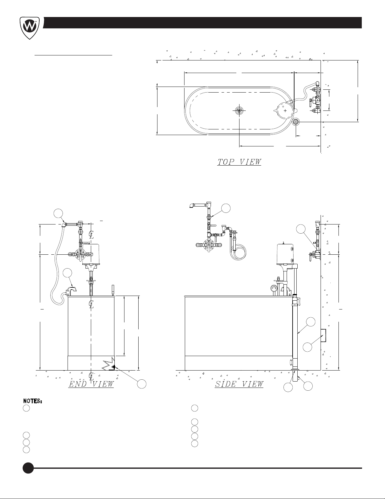
Fixture Installation Location Guide
DIMENSION DESCRIPTION
A
DISTANCE FOR:
MXT2 (MV2) 3/4" NPT
VALVE = 9-1/2"
MXT1 (MV1) 1/2" NPT
VALVE = 8-1/2"
B
DISTANCE FOR:
MXT2 (MV2) 3/4" NPT
VALVE = 13-1/2"
MXT1 (MV1) 1/2" NPT
VALVE = 13-3/4"
L = LENGTH (ID)
W = WIDTH (ID)
D = DEPTH (ID)
OH = OVERALL HEIGHT
CW = CENTER OF TANK TO WALL
CD = CENTER OF DRAIN TO WALL
REFER TO PAGE 5 FOR DIMENSIONS
12"
(305)
REC. MIN.
W
12"
L
(305)
REC. MIN.
CD
A
11"
(279)
CW
B
1
52
4
(1327)
2
3
4
4
(120)
"
7
B
6
3
1
52
"
D
5
4
(1327)
"
OH
1
9
8
4
ELECTRICAL REQUIREMENTS: 8 AMPS, 115 VOLTS.
1
AT WALL PROVIDE ONE 3 POLE RECEPTACLE HOSPITAL
GRADE WITH GROUND FAULT INTERRUPT FOR TURBINE
ASSEMBLY
THERMOSTATIC MIXING VALVES ARE OPTIONAL
2
OPTIONAL -MXWH (HA-WASHOUT ASSEMBLY)
3
2" x 5" TAIL PIECE FURNISHED WITH UNIT
4
4
2" COMBINATION DRAIN AND OVERFLOW ASSEMBLY
5
FURNISHED BY WHITEHALL
OVER RIM INLET
6
HOT & COLD WATER INLET
7
2" DRAIN
8
'L'-CLIPS FOR FLOOR MOUNTING
9
Page 7
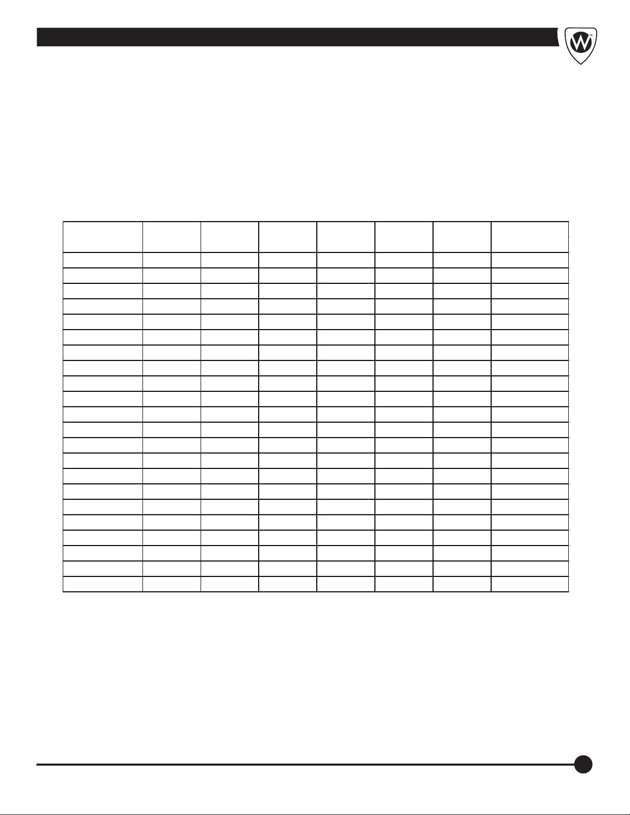
Stationary Style Hydrotherapy Whirlpool Dimensions
P-10-S 22/559 13/330 12/305 18/457 23/584 26.5/673 1/2" IPS
P-15-S 25/635 13/330 15/381 21/533 25.5/648 26.5/673 1/2" or 3/4" IPS
P-22-S 28/711 15/381 18/457 24/610 26/660 26.5/673 1/2" or 3/4" IPS
E-15-S 25/635 13/330 15/381 21/533 25.5/648 26.5/673 1/2" or 3/4" IPS
E-22-S 28/711 15/381 18/457 24/610 26/660 26.5/673 1/2" or 3/4" IPS
E-22-SP 28/711 15/381 18/457 34/864 20/508 26.5/673 1/2" or 3/4" IPS
E-27-S 28/711 15/381 21/533 27/686 26/660 26.5/673 1/2" or 3/4" IPS
E-36-S 28/711 15/381 25/635 32/813 26/660 26.5/673 1/2" or 3/4" IPS
E-45-S 32/813 15/381 25/635 31/787 28/711 26.5/673 1/2" or 3/4" IPS
H-60-S 36/914 20/508 28/711 34/864 30/762 29/737 1/2" or 3/4" IPS
H-75-S 42/1067 20/508 28/711 34/864 33/838 29/737 1/2" or 3/4" IPS
H-90-S 48/1219 20/508 28/711 34/864 36/914 29/737 1/2" or 3/4" IPS
H-105-S 48/1219 24/610 28/711 34/864 26/660 31/787 1/2" or 3/4" IPS
L-75-S 52/1321 24/610 18/457 24/610 38/965 31/787 1/2" or 3/4" IPS
L-90-S 60/1524 24/610 18/457 24/610 42/1067 31/787 1/2" or 3/4" IPS
L-105-S 66/1676 24/610 18/457 24/610 45/1143 31/787 1/2" or 3/4" IPS
S-85-S 48/1219 20/508 25/635 31/787 36/914 29/737 1/2" or 3/4" IPS
S-85-SL 48/1219 20/508 25/635 35/889 17/432 N/A 1/2" or 3/4" IPS
S-90-S 46/1168 24/610 25/635 31/787 35/889 31/787 1/2" or 3/4" IPS
S-90-SL 46/1168 24/610 25/635 35/889 17/432 N/A 1/2" or 3/4" IPS
S-110-S 56/1422 24/610 25/635 31/787 40/1016 31/787 1/2" or 3/4" IPS
S-110-SL 56/1422 24/610 25/635 35/889 17/432 N/A 1/2" or 3/4" IPS
PIPE SIZE FOR
VALVE
Whitehall
Model Number
L DIM
Inches/MM
W DIM
Inches/MM
D DIM
Inches/MM
OH DIM
INCHES/M
CW DIM
INCHES/M
CD DIM
INCHES/M
Refer to Page 4 for Layout Information.
5
Page 8
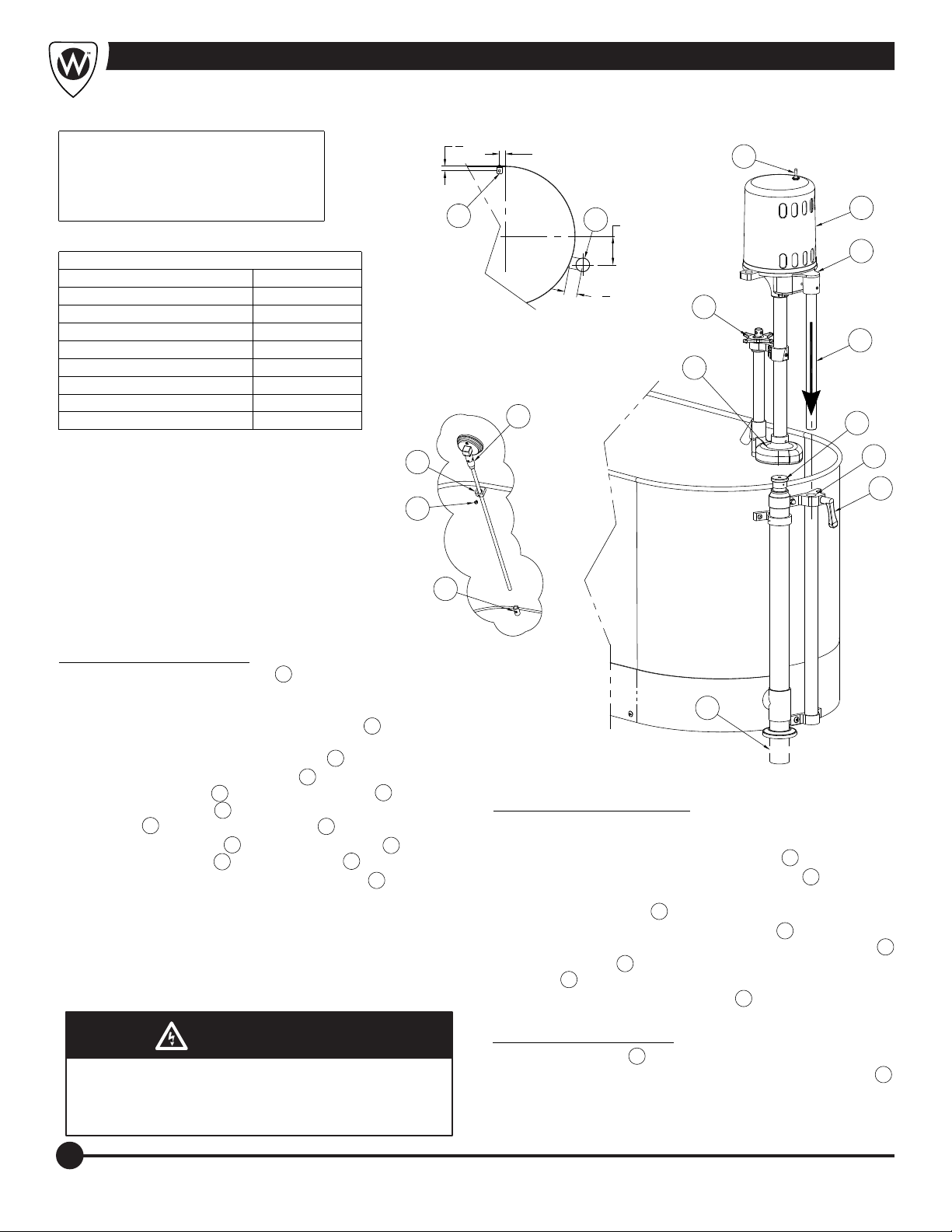
Installation Instructions
NOTE: THESE INSTALLATION
INSTRUCTIONS ARE USED FOR
ALL WHITEHALL OR DAKON
STATIONARY ALL MODELS.
REFERENCE DRAWINGS
ASSEMBLIES
MOTOR/TURBINE 9
RAISING/LOWERING/SM
RAISING/LOWERING 16
DRAIN OVERFLOW E
DRAIN OVERFLOW H/S
DRAIN OVERFLOW - L
THERMOMETER 27
PAGE NUMBER
15
19
18
20
21DRAIN OVERFLOW - P
3
"
4
2
1"
C
L
DETAIL "A"
(TOP VIEW)
7
13
1
5"
3
14
1
2
"
4
11
6
12
15
ASSEMBLY PROCEDURE:
A-
ROUGH-IN FOR 2" OD DRAIN LINE 1 AND WATER INLET VALVE.
(SEE DETAIL A) NOTE: FOR INFORMATION ON OPTIONAL
THERMOSTATIC MIXING VALVE CONTACT FACTORY.
B-
LOCATE TANK AND SECURE WITH "L" BRACKETS 2 , WITH
INSTALLER PROVIDED FLOOR ANCHORS AND ANCHORING
HARDWARE. MAKE WASTE CONNECTIONS 1 .
C-
INSTALL MOTOR/TURBINE ASSEMBLY 3 INTO RAISING AND
LOWERING ASSEMBLY 4 BY LOOSENING HANDLE 5 , SLIDING
MOTOR SUPPORT ROD 6 INTO RAISING AND LOWERING
ASSEMBLY 4 AND TIGHTENING HANDLE 5 .
D-
INSTALL THERMOMETER 7 THRU UPPER BRACKET 8 AND
INTO LOWER BRACKET 9 , TIGHTEN SCREW 10 .
E-
TURN THE PRESSURE CONTROL VALVE HANDLE 11 FULLY
CLOCKWISE, THEN FULLY COUNTERCLOCKWISE TO
COMPLETELY LUBRICATE THE PLUNGER ASSEMBLY.
F-
PROVIDE ELECTRICAL SERVICE AND PROPERLY INSTALLED,
GROUND FAULT CIRCUIT INTERRUPTER (GFCI) FOR MOTOR
SPECIFIED. MOTOR SPECIFICATIONS AVAILABLE ARE EITHER
120V AC / 60 HZ ON 15A CIRCUIT OR 240 V AC / 50 HZ ON 10A
WARNING
WARNING
Turbine assembly is provided with a 3-way plug. The
third prong functions as a built-in ground and must be
plugged into a matching grounded receptacle to
properly ground the product.
8
10
4
5
9
1
OPERATION PROCEDURE:
A-
FILL TUB AS DESIRED USING THERMOSTATIC MIXING VALVE.
WATER LEVEL SHOULD BE A MAXIMUM OF 4" BELOW THE RIM
AND A MINIMUM OF 6" ABOVE BOTTOM PUMP 12 .
B-
TURN THE PRESSURE CONTROL VALVE HANDLE 11 FULLY
CLOCKWISE, THIS PROVIDES MAX PRESSURE AND AGITATION.
C-
TURN ON THE SWITCH 13 .
D-
ADJUST RAISING AND LOWERING ASSEMBLY 4 BY SLOWLY
PUSHING DOWN ON TOP OF THE MOTOR SUPPORT CASTING 14
UNTIL THE PUMP 12 IS AT THE DESIRED LOCATION. TIGHTEN
HANDLE 5 . INTERNAL BUSHING MAY NEED ADJUSTMENT.
E-
ADJUST PRESSURE CONTROL VALVE 11 TO DELIVER DESIRED
LEVEL OF AGITATION AND PRESSURE.
DRAINING PROCEDURE:
A-
TURN OFF SWITCH 13 .
B-
LIFT COMBINATION DRAIN & OVERFLOW ASSEMBLY HANDLE 15 .
6
Page 9
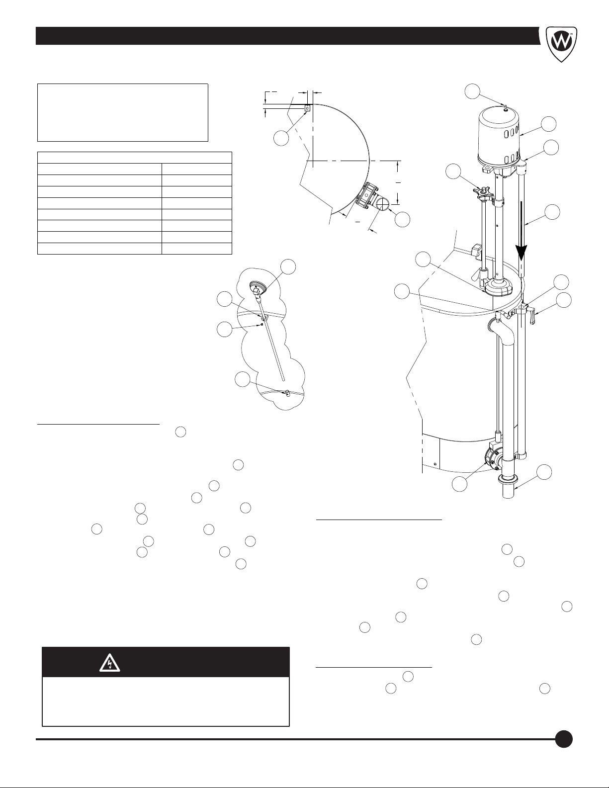
Installation Instructions; -SDO Separate Drain Overflow
Installation Instructions; -SDO Separate Drain Overflow
NOTE: THESE INSTALLATION
INSTRUCTIONS ARE USED FOR
ALL WHITEHALL OR DAKON
ALL STATIONARY -SDO MODELS.
REFERENCE DRAWINGS
ASSEMBLIES
MOTOR/TURBINE 9
RAISING/LOWERING/SM
RAISING/LOWERING 16
DRAIN OVERFLOW E
DRAIN OVERFLOW H/S
THERMOMETER
PAGE NUMBER
15
24
25
23DRAIN OVERFLOW - P
27
8
10
3
"
4
1"
13
3
2
14
C
L
7
7
"
8
1
3
"
2
1
11
6
DETAIL "A"
(TOP VIEW)
7
12
4
15
5
9
ASSEMBLY PROCEDURE:
A-
ROUGH-IN FOR 2" OD DRAIN LINE 1 AND WATER INLET VALVE.
(SEE DETAIL A) NOTE: FOR INFORMATION ON OPTIONAL
THERMOSTATIC MIXING VALVE CONTACT FACTORY.
B-
LOCATE TANK AND SECURE WITH "L" BRACKETS 2 , WITH
INSTALLER PROVIDED FLOOR ANCHORS AND ANCHORING
HARDWARE. MAKE WASTE CONNECTIONS 1 .
C-
INSTALL MOTOR/TURBINE ASSEMBLY 3 INTO RAISING AND
LOWERING ASSEMBLY 4 BY LOOSENING HANDLE 5 , SLIDING
MOTOR SUPPORT ROD 6 INTO RAISING AND LOWERING
ASSEMBLY 4 AND TIGHTENING HANDLE 5 .
D-
INSTALL THERMOMETER 7 THRU UPPER BRACKET 8 AND
INTO LOWER BRACKET 9 , TIGHTEN SCREW 10 .
E-
TURN THE PRESSURE CONTROL VALVE HANDLE 11 FULLY
CLOCKWISE, THEN FULLY COUNTERCLOCKWISE TO
COMPLETELY LUBRICATE THE PLUNGER ASSEMBLY.
F-
PROVIDE ELECTRICAL SERVICE AND PROPERLY INSTALLED,
GROUND FAULT CIRCUIT INTERRUPTER (GFCI) FOR MOTOR
SPECIFIED. MOTOR SPECIFICATIONS AVAILABLE ARE EITHER
120V AC / 60 HZ ON 15A CIRCUIT OR 240 V AC / 50 HZ ON 10A
WARNING
WARNING
Turbine assembly is provided with a 3-way plug. The
third prong functions as a built-in ground and must be
plugged into a matching grounded receptacle to
properly ground the product.
16
OPERATION PROCEDURE:
A-
FILL TUB AS DESIRED USING THERMOSTATIC MIXING VALVE.
WATER LEVEL SHOULD BE A MAXIMUM OF 4" BELOW THE RIM
AND A MINIMUM OF 6" ABOVE BOTTOM PUMP 12 .
B-
TURN THE PRESSURE CONTROL VALVE HANDLE 11 FULLY
CLOCKWISE, THIS PROVIDES MAX PRESSURE AND AGITATION.
C-
TURN ON THE SWITCH 13 .
D-
ADJUST RAISING AND LOWERING ASSEMBLY 4 BY SLOWLY
PUSHING DOWN ON TOP OF THE MOTOR SUPPORT CASTING 14
UNTIL THE PUMP 12 IS AT THE DESIRED LOCATION. TIGHTEN
HANDLE 5 . INTERNAL BUSHING MAY NEED ADJUSTMENT.
E-
ADJUST PRESSURE CONTROL VALVE 11 TO DELIVER DESIRED
LEVEL OF AGITATION AND PRESSURE.
DRAINING PROCEDURE:
A-
TURN OFF SWITCH 13 .
B-
TURN HANDLE 15 CLOCKWISE TO OPEN DRAIN VALVE 16 .
1
7
Page 10
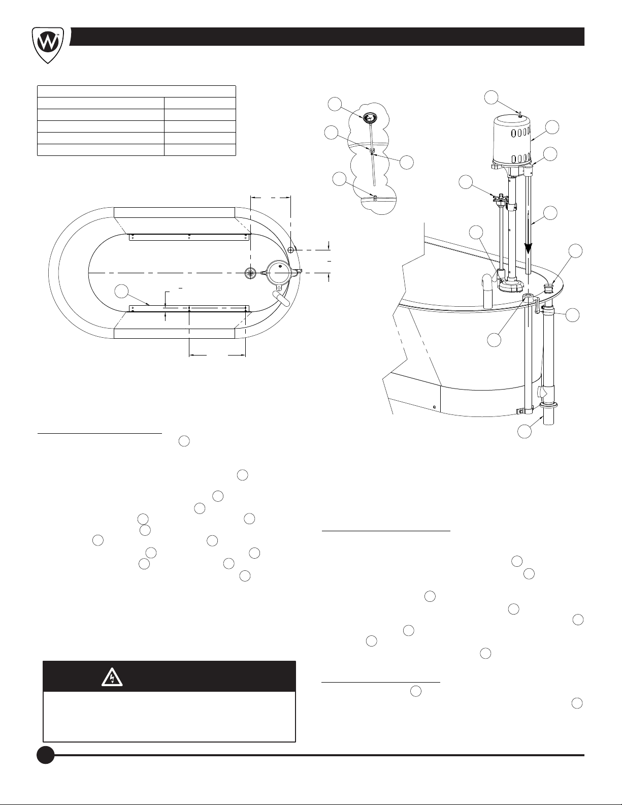
Installation Instructions; Slant Back
REFERENCE DRAWINGS
ASSEMBLIES
MOTOR/TURBINE 9
RAISING/LOWERING
DRAIN OVERFLOW
THERMOMETER
2
PAGE NUMBER
1
1
"
4
TYP.
17
22
27
17"
TYP.
12
DETAIL "A"
(TOP VIEW)
7
8
10
9
1
"
8
7
6
"
8
13
3
14
11
6
12
15
5
4
ASSEMBLY PROCEDURE:
A-
ROUGH-IN FOR 2" OD DRAIN LINE 1 AND WATER INLET VALVE.
(SEE DETAIL A) NOTE: FOR INFORMATION ON OPTIONAL
THERMOSTATIC MIXING VALVE CONTACT FACTORY.
B-
LOCATE TANK AND SECURE WITH "L" BRACKETS 2 , WITH
INSTALLER PROVIDED FLOOR ANCHORS AND ANCHORING
HARDWARE. MAKE WASTE CONNECTIONS 1 .
C-
INSTALL MOTOR/TURBINE ASSEMBLY 3 INTO RAISING AND
LOWERING ASSEMBLY 4 BY LOOSENING HANDLE 5 , SLIDING
MOTOR SUPPORT ROD 6 INTO RAISING AND LOWERING
ASSEMBLY 4 AND TIGHTENING HANDLE 5 .
D-
INSTALL THERMOMETER 7 THRU UPPER BRACKET 8 AND
INTO LOWER BRACKET 9 , TIGHTEN SCREW 10 .
E-
TURN THE PRESSURE CONTROL VALVE HANDLE 11 FULLY
CLOCKWISE, THEN FULLY COUNTERCLOCKWISE TO
COMPLETELY LUBRICATE THE PLUNGER ASSEMBLY.
F-
PROVIDE ELECTRICAL SERVICE AND PROPERLY INSTALLED,
GROUND FAULT CIRCUIT INTERRUPTER (GFCI) FOR MOTOR
SPECIFIED. MOTOR SPECIFICATIONS AVAILABLE ARE EITHER
120V AC / 60 HZ ON 15A CIRCUIT OR 240 V AC / 50 HZ ON 10A
WARNING
WARNING
Turbine assembly is provided with a 3-way plug. The
third prong functions as a built-in ground and must be
plugged into a matching grounded receptacle to
properly ground the product.
1
OPERATION PROCEDURE:
A-
FILL TUB AS DESIRED USING THERMOSTATIC MIXING VALVE.
WATER LEVEL SHOULD BE A MAXIMUM OF 4" BELOW THE RIM
AND A MINIMUM OF 6" ABOVE BOTTOM PUMP 12 .
B-
TURN THE PRESSURE CONTROL VALVE HANDLE 11 FULLY
CLOCKWISE, THIS PROVIDES MAX PRESSURE AND AGITATION.
C-
TURN ON THE SWITCH 13 .
D-
ADJUST RAISING AND LOWERING ASSEMBLY 4 BY SLOWLY
PUSHING DOWN ON TOP OF THE MOTOR SUPPORT CASTING 14
UNTIL THE PUMP 12 IS AT THE DESIRED LOCATION. TIGHTEN
HANDLE 5 . INTERNAL BUSHING MAY NEED ADJUSTMENT.
E-
ADJUST PRESSURE CONTROL VALVE 11 TO DELIVER DESIRED
LEVEL OF AGITATION AND PRESSURE.
DRAINING PROCEDURE:
A-
TURN OFF SWITCH 13 .
B-
LIFT COMBINATION DRAIN & OVERFLOW ASSEMBLY HANDLE 15 .
8
Page 11
THESE REPAIR PARTS ARE USED FOR THE
FOLLOWING MODEL NUMBERS ONLY:
WHITEHALL MODEL
NUMBERS
E-15-M-SDP
E-15-S
E-22-M-SDP
E-22-S
E-22-SP
E-27-M-SDP DD-2821
E-27-S DF-2821
E-36-M-SDP DD-2825
E-36-S DF-2825
E-45-M-SDP
E-45-S
H-60-M-SDP DD-3628
H-60-S
H-75-M-SDP
H-75-S
H-90-M-SDP
H-90-S
H-105-M-SDP DD-4828
H-105-S DF-4828
MODEL NUMBERS
DD-2516
DF-2516
DD-2818
DF-2818
DF-3225
DF-3628
DAKON
WHITEHALL MODEL
NUMBERS
L-75-M-SDP
L-75-S
L-90-M-SDP DD-6018
L-90-S DF-6018
L-90-SL
L-105-M-SDP DD-6618
L-105-S DF-6618
L-105-SL
P-10-S
P-15-M-SDP DD-2516
P-15-S DF-2516
P-22-M-SDP DD-2818
P-22-S DF-2818
S-85-M-SDP
S-85-S
S-90-M-SDP
S-90-S
S-110-M-SDP DDT-5625
S-110-S DFT-5625
SB-100-S
DAKON
MODEL NUMBERS
DDT-4825
DFT-4825
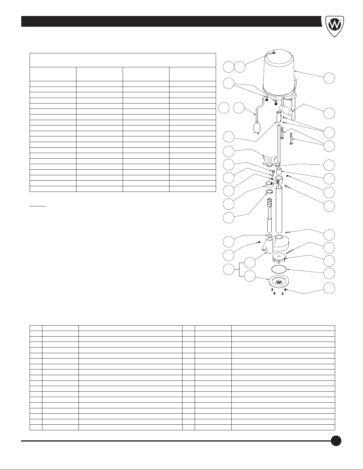
Stationary Motor/Turbine Assembly
14 15
16
17A - 17H
18
19
20
21
22
13
12
11
10
9
8
7
NOTE: SEE ADDITIONAL DRAWINGS FOR
23
COMPLETE ASSEMBLY NUMBERS AND
DETAIL OF ITEMS NOT LISTED.
STATIONARY ''E'' SERIES
STATIONARY ''SB'' SERIES
Page 10
Page 10
STATIONARY ''H'' SERIES Page 11
STATIONARY ''L'' SERIES
STATIONARY ''P'' SERIES
STATIONARY ''S'' SERIES
Page 12
Page 13
Page 14
24
25
26
29
27
28
ITEM PART NUMBER DESCRIPTION ITEM PART NUMBER DESCRIPTION
1 6502-307-000 #8-32 x 1/2" PHIL FLAT HD SELF TAPPING
2 6504-501-199 17" PUMP GASKET
3 6525-518-000 TURBINE IMPELLER - PLASTIC
4 0341-101-000 COTTER PIN
5 6502-401-000 1/4"-20 x 5/16" HEX SOCKET SET SCREW
6 6502-042-000 1/4"-20 x 5/8" PHIL PAN HEAD SCREW
7 6502-300-000 #8-32 x 3/8" PHIL FLAT HEAD SELF TAPPING
8 6525-514-199 SHAFT BEARING
9 6502-410-000 1/4"-20 x 1/4" DOG SET SCREW
10 6502-352-000 3/8"-16 x 3" HEX CAP SCREW
11 6502-402-000 5/16"-16 x 1/4" HEX SOCKET SET SCREW
12 6502-020-001 CONDENSER ASSEMBLY
13 6525-600-000 PLASTIC MOTOR COVER
14 6505-025-000 DPST TOGGLE SWITCH
15 6505-035-000 WATERPROOF TOGGLE SWITCH CAP
16 6502-452-000 3/8"-16 x 3/4" HEX SOCKET CAP SCREW
17A 6505-030-000 10 FEET, 115VAC, 60Hz POWER CORD
17B 6505-034-001 DOMESTIC POWER CORD 220VAC, 60Hz
17C 6505-044-001 RUSSIAN POWER CORD, 250VAC, 50Hz
17D 6505-074-001 INDIA/S. AFRICA POWER CORD, 230VAC, 50Hz
17E 6505-043-001 EUROPEAN POWER CORD, 250 VAC, 50Hz
17F 6505-073-001 UK POWER CORD, 230VAC, 50Hz
17G 6505-070-001 ISRAEL POWER CORD, 250VAC, 50Hz
17H 6505-071-001 AUSTRALIAN POWER CORD, 250VAC 50Hz
18 6525-513-199
19 6525-584-199 HANDLE
20 6531-112-199 TENSION ADJUSTER
21 6531-111-199 FRICTION LOCK ROD
22 6531-113-000 SPRING
23 6525-570-199 AIR RING BRACKET
24 6502-620-000 1-3/8" RETAINING RING
25 6504-022-000 O-RING
26 6502-413-000 1/4"-20 x 5/16" DOG SETR SCREW
27 6525-509-001 PUMP BODY / COVER ASSEMBLY
28 6525-509-299 PUMP COVER
29 6525-510-299 PUMP BODY
SHAFT COUPLING
6
5
4
3
2
1
9
Page 12
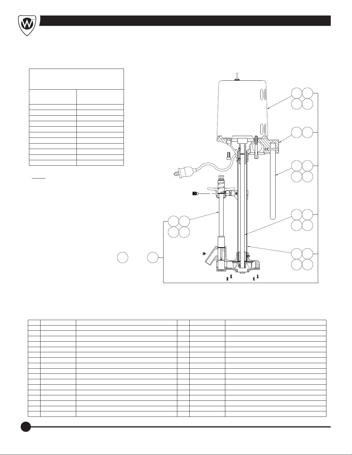
Stationary “E” Series Parts Diagram
THESE REPAIR PARTS ARE USED
FOR THE FOLLOWING MODEL
NUMBERS ONLY:
WHITEHALL MODEL
NUMBERS
E-15-M-SDP
E-15-S
E-22-M-SDP
E-22-S
E-22-SP
E-27-M-SDP DD-2821
E-27-S
E-36-S DF-2825
E-45-M-SDP
E-45-S
SB-100-S
*
NOTE: SEE ADDITIONAL DRAWING FOR DETAIL
OF ITEMS NOT SHOWN.
DAKON
MODEL NUMBERS
DD-2516
DF-2516
DD-2818
DF-2818
DF-2821
DF-3225
3B3A
3D
3C
4A 4B
5A 5B
5C
5D
STATIONARY MOTOR/TURBINE - PAGE 9
2B2A
2C 2D
*
1A 1M
THRU
ITEM PART NUMBER DESCRIPTION ITEM PART NUMBER DESCRIPTION
1A 6525-105-001 TURBINE ASSY - E-15, 115VAC, 60Hz
1B 6525-106-001 TURBINE ASSY - E-15, 230VAC, 60Hz
1C 6525-107-001 TURBINE ASSY - E-15, 230VAC, 50Hz
1D 6525-108-001 TURBINE ASSY - E-22, 115VAC, 60Hz
1E 6525-109-001 TURBINE ASSY - E-22, 230VAC, 60Hz
1F 6525-110-001 TURBINE ASSY - E-22, 230VAC, 50Hz
1G 6525-161-001 TURBINE ASSY - E-27, 115VAC, 60Hz
1H 6525-162-001 TURBINE ASSY - E-27, 230VAC, 60Hz
1J 6525-163-001 TURBINE ASSY - E-27, 230VAC, 50Hz
1K 6525-165-001 TURBINE ASSY - E-45, 115VAC, 60Hz
1L 6525-166-001 TURBINE ASSY - E-45, 230VAC, 60Hz
1M 6525-167-001 TURBINE ASSY - E-45, 230VAC, 50Hz
2A 6525-525-001 PLUNGER ASSY - 12" - E-15-S
2B 6525-528-001 PLUNGER ASSY - 15-1/4" - E-22-S
2C 6525-531-001 PLUNGER ASSY - 16-1/2" - E-27-S
2D 6525-535-001 PLUNGER ASSY - 20" - E-45-S
3A
6525-200-001 MOTOR ASSY - 115VAC, 60Hz - E-27/45-S
6525-201-001 MOTOR ASSY - 115VAC, 60Hz - E-15/223B
6525-210-001 MOTOR ASSY - 230VAC, 60Hz - E-15/22/27/45-S3C
6525-220-001 MOTOR ASSY - 230VAC, 50Hz - E-15/22/27/45-S3D
6525-500-199 3/4" MOTOR BASE CASTING - E-15/22-S4A
6525-500-299 1" MOTOR BASE CASTING - E-27/45-S4B
6509-560-199 3/4" DIA. x 13" ROD - E-155A
6509-565-199 3/4" DIA. x 16" ROD - E-225B
6509-160-199 1" DIA. x 21-1/4" ROD - E-275C
6509-165-199 1" DIA. x 23-1/2" ROD - E-455D
6509-510-199 IMPELLER SHAFT - 16-1/8" - E-156A
6509-515-199 IMPELLER SHAFT - 19-1/8" - E-226B
6509-520-199 IMPELLER SHAFT - 22-1/8" - E-276C
6509-525-199 IMPELLER SHAFT - 26-3/8" - E-456D
6509-110-199 IMPELLER TUBE - 15-1/4" - E-157A
6509-115-199 IMPELLER TUBE - 18-1/4" - E-227B
6509-120-199 IMPELLER TUBE - 21-1/4" - E-277C
6509-125-199 IMPELLER TUBE - 25-1/2" - E-457D
6B6A
6D
6C
7A 7B
7D7C
10
Page 13
THESE REPAIR PARTS ARE USED
FOR THE FOLLOWING MODEL
NUMBERS ONLY:
WHITEHALL MODEL
NUMBERS
H-60-M-SDP
H-60-S
H-75-M-SDP
H-75-S
H-90-M-SDP
H-90-S
H-105-M-SDP DD-4828
H-105-S
*
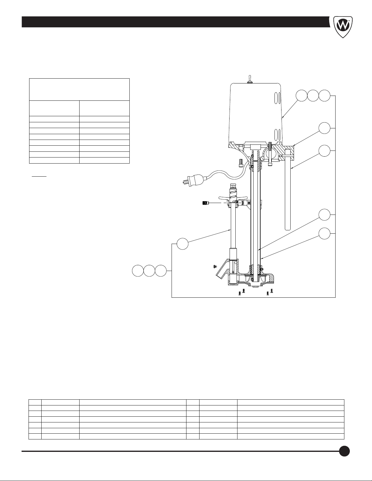
NOTE: SEE ADDITIONAL DRAWING FOR
DETAIL OF ITEMS NOT SHOWN.
STATIONARY MOTOR/TURBINE - PAGE 9
DAKON
MODEL NUMBERS
DD-3628
DF-3628
DF-4828
Stationary “H” Series Parts Diagram
3B3A
3C
4
5
6
7
2
*
1C1B1A
ITEM PART NUMBER DESCRIPTION ITEM PART NUMBER DESCRIPTION
1A 6525-168-001 TURBINE ASSY - H-60/75/90/105 - 115VAC, 60Hz
1B 6525-169-001 TURBINE ASSY - H-60/75/90/105 - 230VAC, 60Hz
1C 6525-170-001 TURBINE ASSY - H-60/75/90/105 - 230VAC, 50Hz
2 6525-538-001 PLUNGER ASSY - 23-1/4" - H-60/75/90/105-S
3A 6525-200-001 MOTOR ASSY - 115VAC, 60Hz
3B 6525-210-001 MOTOR ASSY - 230VAC, 60Hz
3C 6525-220-001 MOTOR ASSY - 230VAC, 50Hz
4 6525-500-299 1" MOTOR BASE CASTING -S
5 6509-170-199 1" DIA. x 25-1/2" TUBING R & L DEVICES
6 6509-530-199 IMPELLER SHAFT - 29-3/8"
7 6509-130-199 IMPELLER TUBE - 28-1/2"
11
Page 14
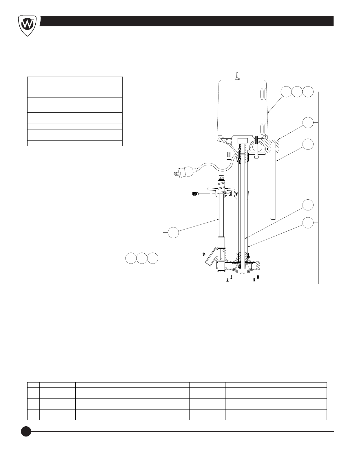
Stationary “L” Series Parts Diagram
THESE REPAIR PARTS ARE USED
FOR THE FOLLOWING MODEL
NUMBERS ONLY:
WHITEHALL MODEL
NUMBERS
L-75-M-SDP
L-75-S
L-90-M-SDP
L-90-S
L-105-M-SDP
L-105-S
*
NOTE: SEE ADDITIONAL DRAWING FOR
DETAIL OF ITEMS NOT SHOWN.
STATIONARY MOTOR/TURBINE - PAGE 9
DAKON
MODEL NUMBERS
DD-6018
DF-6018
DD-6618
DF-6618
3C
3B3A
4
5
6
7
2
*
1C1B1A
ITEM PART NUMBER DESCRIPTION ITEM PART NUMBER DESCRIPTION
1A 6525-158-001 TURBINE ASSY - L-75/90/105 - 115VAC, 60Hz
1B 6525-159-001 TURBINE ASSY - L-75/90/105 - 230VAC, 60Hz
1C 6525-160-001 TURBINE ASSY - L-75/90/105 - 230VAC, 50Hz
2 6525-528-001 PLUNGER ASSY - 15-1/4'
3A 6525-200-001 MOTOR ASSY - 115VAC, 60Hz
3B 6525-210-001 MOTOR ASSY - 230VAC, 60Hz
3C 6525-220-001 MOTOR ASSY - 230VAC, 50Hz
4 6525-500-299 MOTOR BASE CASTING R & L -S
5 6525-155-199 1" DIA. x 16-1/2" ROD
6 6509-515-199 IMPELLER SHAFT - 19-1/8"
7 6509-115-199 IMPELLER TUBE - 18-1/4"
12
Page 15
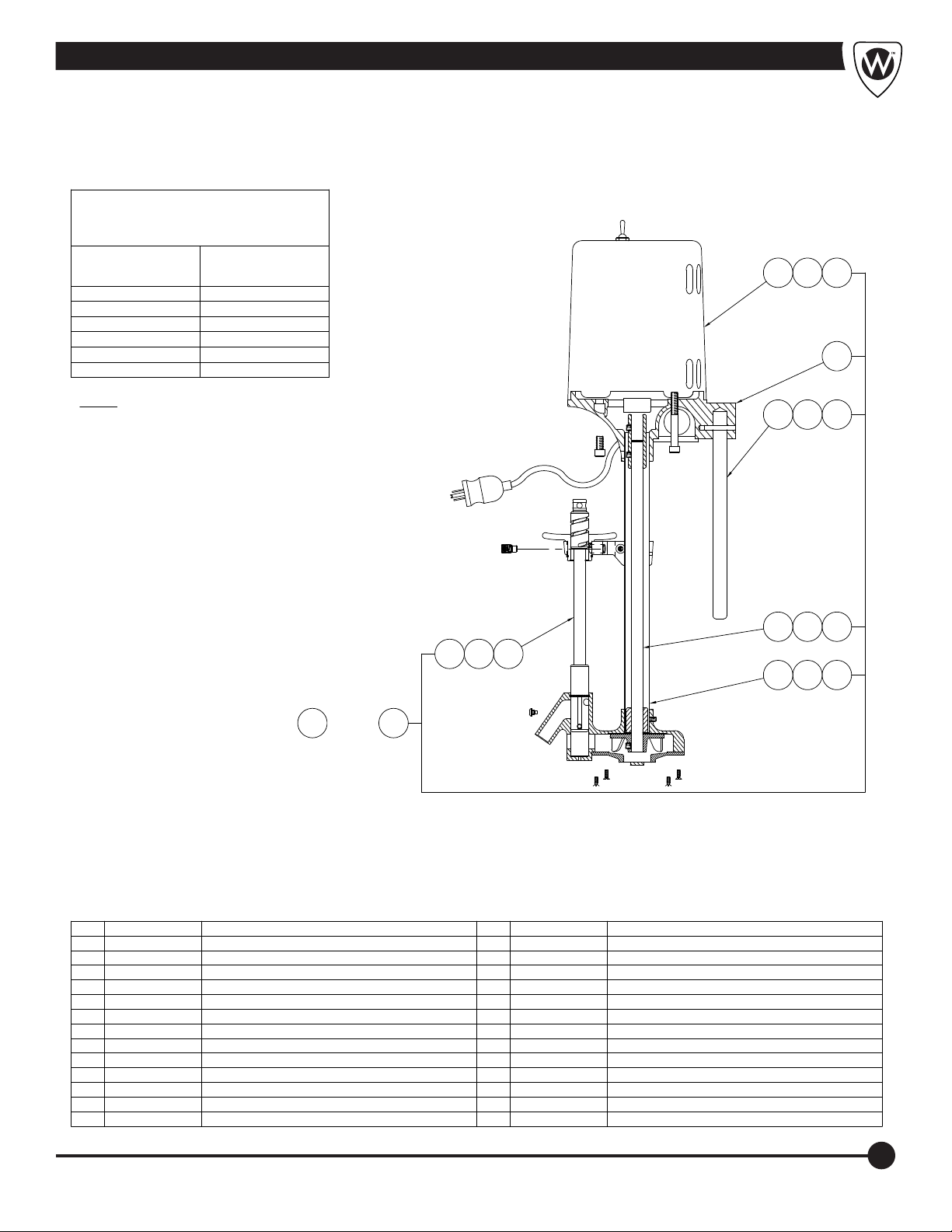
THESE REPAIR PARTS ARE USED
FOR THE FOLLOWING MODEL
NUMBERS ONLY:
WHITEHALL MODEL
NUMBERS
P-10-M-SDP
P-10-S
P-15-M-SDP
P-15-S
P-22-M-SDP
P-22-S
*
NOTE: SEE ADDITIONAL DRAWING FOR
DETAIL OF ITEMS NOT SHOWN.
STATIONARY MOTOR/TURBINE - PAGE 9
DAKON
MODEL NUMBERS
DD-2516
DF-2516
DD-2818
DF-2818
Stationary “P” Series Parts Diagram
3C3B3A
4
5A 5B 5C
2A 2B 2C
7A 7B 7C
*
1A
THRU
ITEM PART NUMBER DESCRIPTION ITEM PART NUMBER DESCRIPTION
1A 6528-102-001 TURBINE ASSY - P-10 - 115VAC, 60Hz
1B 6528-103-001 TURBINE ASSY - P-10 - 230VAC, 60Hz
1C 6528-104-001 TURBINE ASSY - P-10 - 230VAC, 50Hz
1D 6528-105-001 TURBINE ASSY - P-15 - 115VAC, 60Hz
1E 6528-106-001 TURBINE ASSY - P-15 - 230VAC, 60Hz
1F 6528-107-001 TURBINE ASSY - P-15 - 230VAC, 50Hz
1G 6528-108-001 TURBINE ASSY - P-22 - 115VAC, 60Hz
1H 6528-109-001 TURBINE ASSY - P-22 - 230VAC, 60Hz
1J 6528-110-001 TURBINE ASSY - P-22 - 230VAC, 50Hz
2A 6528-522-001 PLUNGER ASSY - 9-1/2" - P-10
2B 6528-525-001 PLUNGER ASSY - 12" - P-15
2C 6528-528-001 PLUNGER ASSY - 15-1/4" - P-22
3A 6528-201-001 MOTOR ASSY - 115VAC, 60Hz - P-11/15/22
1J
3B 6528-210-001 MOTOR ASSY - 230VAC, 60Hz - P-11/15/22
3C 6528-220-001 MOTOR ASSY - 230VAC, 50Hz - P-11/15/22
4 6528-500-199 3/4" MOTOR BASE CASTING -S
5A 6509-555-199 3/4" DIA. x 11-1/2" ROD - P-10
5B 6509-560-199 3/4" DIA. x 13" ROD - P-15
5C 6509-565-199 3/4" DIA. x 16" ROD - P-22
6A 6509-505-199 IMPELLER SHAFT - 13-7/8" - P-10
6B 6509-510-199 IMPELLER SHAFT - 16-1/8" - P-15
6C 6509-515-199 IMPELLER SHAFT - 19-1/8" - P-22
7A 6509-105-199 IMPELLER TUBE - 13" - P-10
7B 6509-110-199 IMPELLER TUBE - 15-1/4" - P-15
7C 6509-115-199 IMPELLER TUBE - 18-1/4" - P-22
6C6B6A
13
Page 16
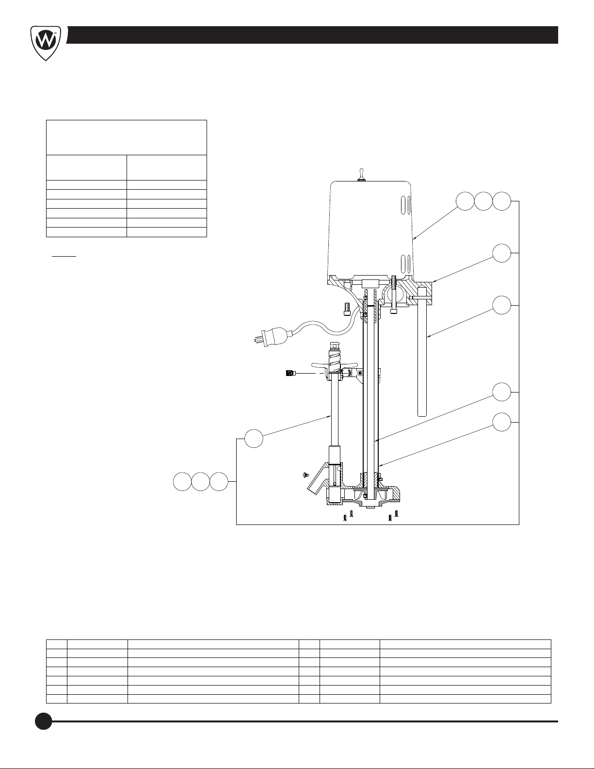
Stationary “S” Series Parts Diagram
THESE REPAIR PARTS ARE USED
FOR THE FOLLOWING MODEL
NUMBERS ONLY:
WHITEHALL MODEL
NUMBERS
S-85-M-SDP
S-85-S
S-90-M-SDP
S-90-S
S-110-M-SDP
S-110-S
*
NOTE: SEE ADDITIONAL DRAWING FOR
DETAIL OF ITEMS NOT SHOWN.
STATIONARY MOTOR/TURBINE - PAGE 9
DAKON
MODEL NUMBERS
DFT-4825
DFT-5625
3C
3B3A
4
5
2
*
ITEM PART NUMBER DESCRIPTION ITEM PART NUMBER DESCRIPTION
1A 6525-165-001 TURBINE ASSY S-85/90/110 - 115VAC, 60Hz
1B 6525-166-001 TURBINE ASSY S-85/90/110 - 230VAC, 60Hz
1C 6525-167-001 TURBINE ASSY S-85/90/110 - 230VAC, 50Hz
2 6525-535-001 PLUNGER ASSEMBLY 20"
3A 6525-200-001 MOTOR ASSEMBLY - 115VAC, 60Hz
3B 6525-210-001 MOTOR ASSEMBLY - 230VAC, 60Hz
1C1B1A
3C 6525-220-001 MOTOR ASSEMBLY - 230VAC, 50Hz
4 6525-500-299 1" DIA. MOTOR BASE CASTING
5 6509-165-199 1" DIA. x 23-1/2" ROD
6 6509-525-199 IMPELLER SHAFT - 26-3/8"
7 6509-125-199 IMPELLER TUBE - 25-1/2"
6
7
14
Page 17
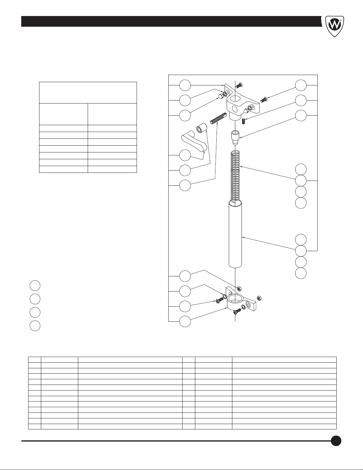
Motor Raising & Lowering Assembly (Small)
THESE REPAIR PARTS ARE USED
FOR THE FOLLOWING MODEL
NUMBERS ONLY:
WHITEHALL
MODEL
NUMBERS
E-15-S
DAKON
MODEL
NUMBERS
DF-2516
E-22-MU
E-22-S
DF-2818
E-22-SP
P-10-S
P-15-S DF-2516
P-22-S
DF-2818
7
8
9 4
10
11
12
6
5
3A
3B
3C
3D
2A
2B
13
R & L ASSY P-10-S
1A
8
R & L ASSY P/E-15-S
1B
6
R & L ASSY P/E-22-MU/SP
1C
R & L ASSY P/E-22-S
1D
ITEM PART NUMBER DESCRIPTION ITEM PART NUMBER DESCRIPTION
1A 6530-015-001 3/4" DIM. R & L ASSEMBLY - P-10-S
1B 6530-025-001 3/4" DIM. R & L ASSEMBLY - P/E-15-S
1C 6530-030-001 3/4" DIM. R & L ASSEMBLY - P/E-22-MU/SP
1D 6530-045-001 3/4" DIM. R & L ASSEMBLY - P/E-22-S
2A 6509-205-199 1-1/8" DIA. x 12-1/8" TUBE - P-10-S
2B 6509-215-199 1-1/8" DIA. x 18" TUBE - P/E-15-S
2C 6509-215-199 1-1/8" DIA. x 18" TUBE - P/E-22-MU/SP
2D 6509-225-199 1-1/8" DIA. x 20" TUBE - P/E-22-S
3A 6503-005-000 7/8" DIA. x 13" SPRING - P-10-S
3B 6503-015-000 7/8" DIA. x 9" SPRING - P/E-15-S
3C 6503-015-000 7/8" DIA. x 9" SPRING - P/E-22-MU/SP
3D 6503-030-000 7/8" DIA. x 23" SPRING - P/E-22-S
14
4 6530-110-199 END CAP
5 6502-411-000 1/4"-20 x 5/16" ALLEN HEAD SET SCREW
6 6502-200-000 1/4"-20 x 5/8" PHILLIPS TRUSS HEAD MACH SCRW
7 6530-100-199 UPPER BRACKET
8 0337-050-000 1/4" STAINLESS STEEL LOCKWASHER
9 6502-520-000 1/4"-20 HIGH CROWN ACORN NUT
10 6530-111-199 HANDLE
11 6530-112-199 BUSHING
12 6530-114-199 STUD
13 0302-005-000 1/4"-20 HEX NUT
14 6530-101-199 LOWER BRACKET
2C
2D
15
Page 18
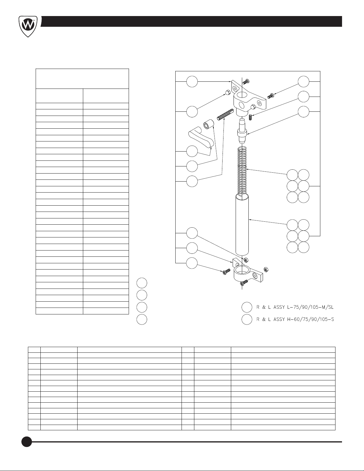
Motor Raising & Lowering Assembly
THESE REPAIR PARTS ARE USED
FOR THE FOLLOWING MODEL
NUMBERS ONLY:
WHITEHALL
MODEL NUMBERS
E-27-S
E-36-S
E-45-S DF-3225
H-60-S
H-75-S
H-90-S
H-105-S
L-75-M
L-75-M-SDP
L-75-SL
L-75-S
L-90-M
L-90-M-DS
L-90-M-SDP
L-90-S DF-6018
L-90-SL
L-105-M
L-105-M-DS
L-105-M-SDP
L-105-S
L-105-SL
S-85-M
S-85-S
S-85-SL
S-90-M
S-90-M-SDP
S-90-S
S-90-SL
S-110-M
S-110-M-SDP DDT-5625
S-110-S
S-110-SL
DAKON
MODEL NUMBERS
DF-2821
DF-2825
DF-3628
DF-4828
DF-6618
DDT-4825S-85-M-SDP
DFT-4825
DST-5625
DFT-5625
10
11
12
13
R & L ASSY E-27-S
1A
R & L ASSY E-45-/S-85/90/110-S
1B
R & L ASSY H-60/75/90/105-S
1C
R & L ASSY L-75/90/105-S
7
8 4
9
3D
3A
3E
3B
3F
3C
2D
2A
2E
2B
2F
2C
6
1E
1F1D
6
5
ITEM PART NUMBER DESCRIPTION ITEM PART NUMBER DESCRIPTION
1A 6530-220-001 1" DIA. R & L ASSY - E-27-S
1B 6530-235-001 1" DIA. R & L ASSY - E-45/S-85/90/110-S
1C 6530-245-001 1" DIA. R & L ASSY - H-60/75/90/105-S
1D 6530-215-001 1" DIA. R & L ASSY - L-75/90/105-S
1E 6530-210-001 1" DIA. R & L ASSY - L-75/90/105-M/SL
1F 6530-225-001 1" DIA. R & L ASSY - E-45-SL/S-85/90/110-M/SL
2A 6509-265-199 1-3/8" DIA. x 23-1/2" TUBE - E-27-S
2B 6509-275-199 1-3/8" DIA. x 27-1/4" TUBE - E-45/S-85/90/110-S
2C 6509-280-199 1-3/8" DIA. x 30-1/2" TUBE - H-60/75/90/105-S
2D 6509-260-199 1-3/8" DIA. x 21-1/4" TUBE - L-75/90/105-S
2E 6509-255-199 1-3/8" DIA. x 18-1/2" TUBE - L-75/90/105-M/S
2F 6509-270-199 1-3/8" DIA. x 18-1/2" TUBE - S-85/90/110-M/SL
3A 6503-265-000 1-1/8" x 23-1/2" SPRING - E-27-S
3B 6503-070-000 1-1/8" x 30-1/2" SPRING - E-45/S-85/90/110-S
3C 6503-075-000 1-1/8" x 34" SPRING - H-60/75/90/105-S
3D 6503-060-000 1-3/8" x 23-1/2" SPRING - L-75/90/105-S
3E 6503-055-000 1-18" x 19" SPRING - L-75/90/105-M/S
3F 6503-065-000 1-18" x 27" SPRING - S-58/90/110-M/SL
4 6530-310-199 END CAP
5 6502-411-000 SET SCREW
6 6502-200-000 1/4"-20 x 5/8" TRUSS HEAD PHILLIPS MS
7 6530-300-199 UPPER BRACKET
8 6502-520-000 1/4"-20 HIGH CROWN ACORN NUT
9 6530-111-199 HANDLE
10 6530-112-199 BUSHING
11 6530-114-199 STUD
12 0302-005-000 1/4"-20 HEX NUT
13 6530-301-199 LOWER BRACKET
16
Page 19
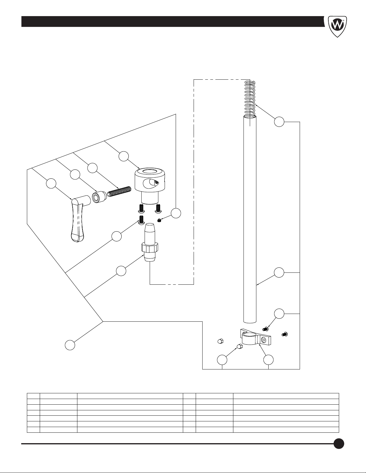
Motor Raising & Lowering Assembly (Slant Back)
12
3
4
5
6
2
7
8
11
SCALED x 1-1/2
7
1
9
10
ITEM PART NUMBER DESCRIPTION ITEM PART NUMBER DESCRIPTION
1 6530-260-001 R & L ASSEMBLY
2 6502-401-000 1/4"-20 x 5/16 SET SCREW
3 6530-411-199 LOCKING HUB
4 6530-114-199 3/8"-16 UNC STUD
5 6530-112-199 BUSHING
6 6530-111-199 LOCKING HANDLE
7 0116-104-000 1/4"-20 x 1/2" PHILLIPS ROUND HEAD SCREW
8 6530-310-199 END CAP
9 6530-520-000 1/4"-20 STAINLESS STEEL ACORN NUT
10 6530-301-199 LOWER BRACKET
11 6509-265-199 1-3/8" DIA. x 23-1/2" R & L TUBE
12 6503-065-000 1-1/8" DIA. x 27" SPRING
17
Page 20
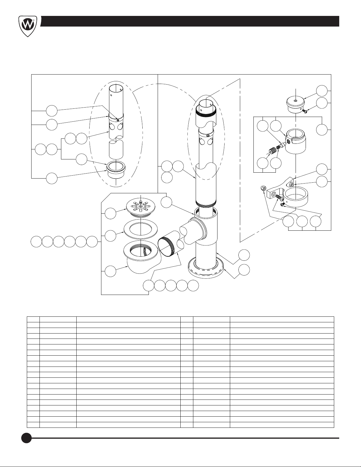
Drain / Overflow Assembly - H/S Series
14
13
14
27
28 29
12
11
31
30
1A 1B 1C 1D 1E 1F
23
10
2A
24
5
2526
15
16
17
9
8
1820 19
7
21
6
3
2B2A 4 5
22
ITEM PART NUMBER DESCRIPTION ITEM PART NUMBER DESCRIPTION
1A 6531-010-001 DRAIN & OVERFLOW - H-60-S
1B 6531-012-001 DRAIN & OVERFLOW - H-75-S
1C 6531-011-001 DRAIN & OVERFLOW - H-90/105-S
1D 6531-015-001 DRAIN & OVERFLOW - S-85-S
1E 6531-014-001 DRAIN & OVERFLOW - S-90-S
1F 6531-016-001 DRAIN & OVERFLOW - S-110-S
2A 6509-346-199 2" O.D. x 17-3/4" DRAIN TUBE - H-60-S
2B 6509-360-199 2" O.D. x 20-3/8" DRAIN TUBE - H-75-S
3 6509-370-199 2" O.D. x 23-5/8" DRN TUBE - H-90/105-S/-85-S
4 6509-365-199 2" O.D. x 22-3/8" DRAIN TUBE - S-90-S
5 6509-385-199 2" O.D. x 27-1/2" DRAIN TUBE - S-110-S/HI-BOY
6 6508-000-199 DRAIN ELBOW
7 6504-500-000 DRAIN GASKET
8 6508-050-199 STRAINER
9 6508-010-199 DRAIN TEE
10 6509-375-199 2" O.D. x 24" DRAIN TUBE - SPORTS
11 6531-056-001 33-1/4" OVERFLOW ASSEMBLY - HI-BOY
12 6531-055-001 29-5/8" OVERFLOW ASSEMBLY
13 6531-102-199 HANDLE
14 6502-450-000 #8-32 x 3/8" PHILLIPS PAN HEAD SCREW
15 6531-110-001 FRICTION LOCK ASSEMBLY
16 6531-100-001 OVERFLOW BRACE
17 0337-050-000 1/4" STN STL HELICAL LOCKWASHER
18 6502-103-000 #8-32 x 1/4" PHILLIPS PAN HEAD SCREW
19 6502-200-000 1/4"-20 x 5/8" PHILLIPS TRUSS HEAD SCREW
20 6502-520-000 1/4"-20 ACORN NUT
21 6509-405-199 2" O.D. x 5" DRAIN TUBE
22 6531-104-000 ESCUTCHEON
23 6531-110-199 FRICTION LOCK HOUSING
24 6531-111-199 FRICTION LOCK ROD
25 6531-113-000 SPRING
26 6531-112-199 TENSION ADAPTER
27 6531-101-199 COLLAR (UP-STOP)
28 6509-085-199 33-1/4" OVERFLOW TUBE
29 6509-080-199 29-5/8' OVERFLOW TUBE
30 6504-221-000 O-RING
31 6531-103-199 O-RING COUPLING
18
Page 21
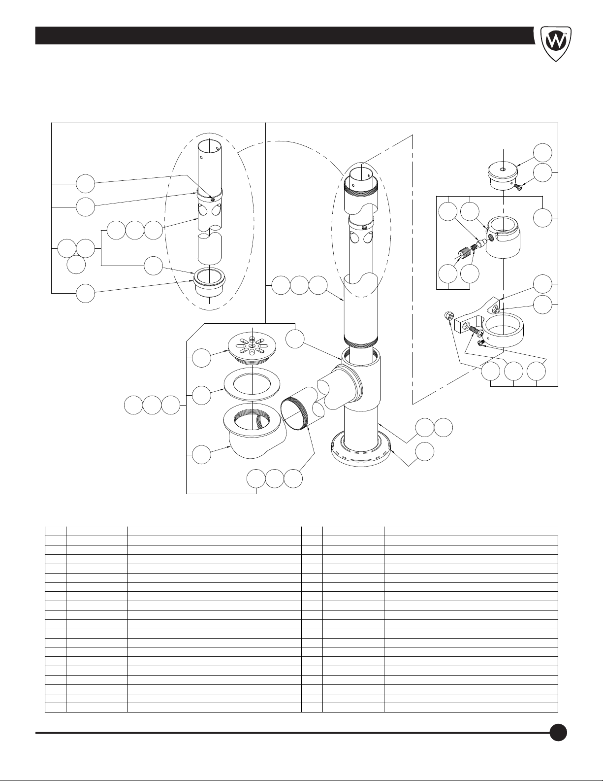
10
Drain /Overflow Assembly - “E” Series
9
10
8B
8A
23
8C
25
24A
24B
1A 1B 1C
24C
26
19
20
11
2122
7A
7B
7C
12
13
6
5
1416 15
4
17A
17B
3
2C
2B2A
18
ITEM PART NUMBER DESCRIPTION ITEM PART NUMBER DESCRIPTION
1A 6531-018-001 DRAIN & OVERFLOW ASSEMBLY - E-22-P
1B 6531-017-001 DRAIN & OVERFLOW ASSEMBLY - E-27-S
1C 6531-013-001 DRAIN & OVERFLOW ASSEMBLY - E-45-S
2A 6509-305-199 2" O.D. x 7-3/8" DRAIN TUBE - E-22-SP
2B 6509-325-199 2" O.D. x 13-3/4" DRAIN TUBE - E-27-S
2C 6509-335-199 2" O.D. x 15-1/2" DRAIN TUBE - E-45-S
3 6508-000-199 DRAIN ELBOW
4 6504-500-000 DRAIN GASKET
5 6508-050-199 STRAINER
6 6508-010-199 DRAIN TEE
7A 6509-350-199 2" O.D. x 19" DRAIN TUBE - E-22-SP
7B 6509-355-199 2" O.D. x 20" DRAIN TUBE - E-27-S
7C 6509-375-199 2" O.D. x 24" DRAIN TUBE - E-45-S
8A 6531-053-001 25" OVERFLOW ASSEMBLY - E-22-SP
8B 6531-054-001 26" OVERFLOW ASSEMBLY - E-27-S
8C 6531-055-001 29-5/8" OVERFLOW ASSEMBLY - E-45-S
9 6531-102-199 HANDLE
10 6502-450-000 #8-32 x 3/8" PAN HEAD PHILLIPS SCREW
11 6531-110-001 FRICTION LOCK ASSEMBLY
12 6531-100-199 OVERFLOW BRACE
13 0337-050-000 1/4" HELICAL STAINLESS STEEL LOCKWASHER
14 6502-103-000 #8-32 x 1/4" PAN HEAD PHILLIPS SCREW
15 6502-200-000 1/4"-20 x 5/8" PHILLIPS TRUSS HEAD SCREW
16 6502-520-000 1/4"-20 ACORN NUT
17A 6509-405-199 2" O.D. x 5" DRAIN TUBE
17B 6509-435-199 2" O.D. x 16" DRAIN TUBE - E-22-SP
18 6531-104-000 ESCUTCHEON
19 6531-110-199 FRICTION LOCK HOUSING
20 6531-111-199 FRICTION LOCK ROD
21 6531-113-000 SPRING
22 6531-112-199 TENSION ADAPTER
23 6531-101-199 COLLAR (UP-STOP)
24A 6509-070-199 25" OVERFLOW TUBE - E-22-SP
24B 6509-075-199 26" OVERFLOW TUBE - E-27-S
24C 6509-080-199 29-5/8" OVERFLOW TUBE -E-45-S
25 6504-221-000 O-RING
26 6531-103-199 O-RING COUPLING
19
Page 22
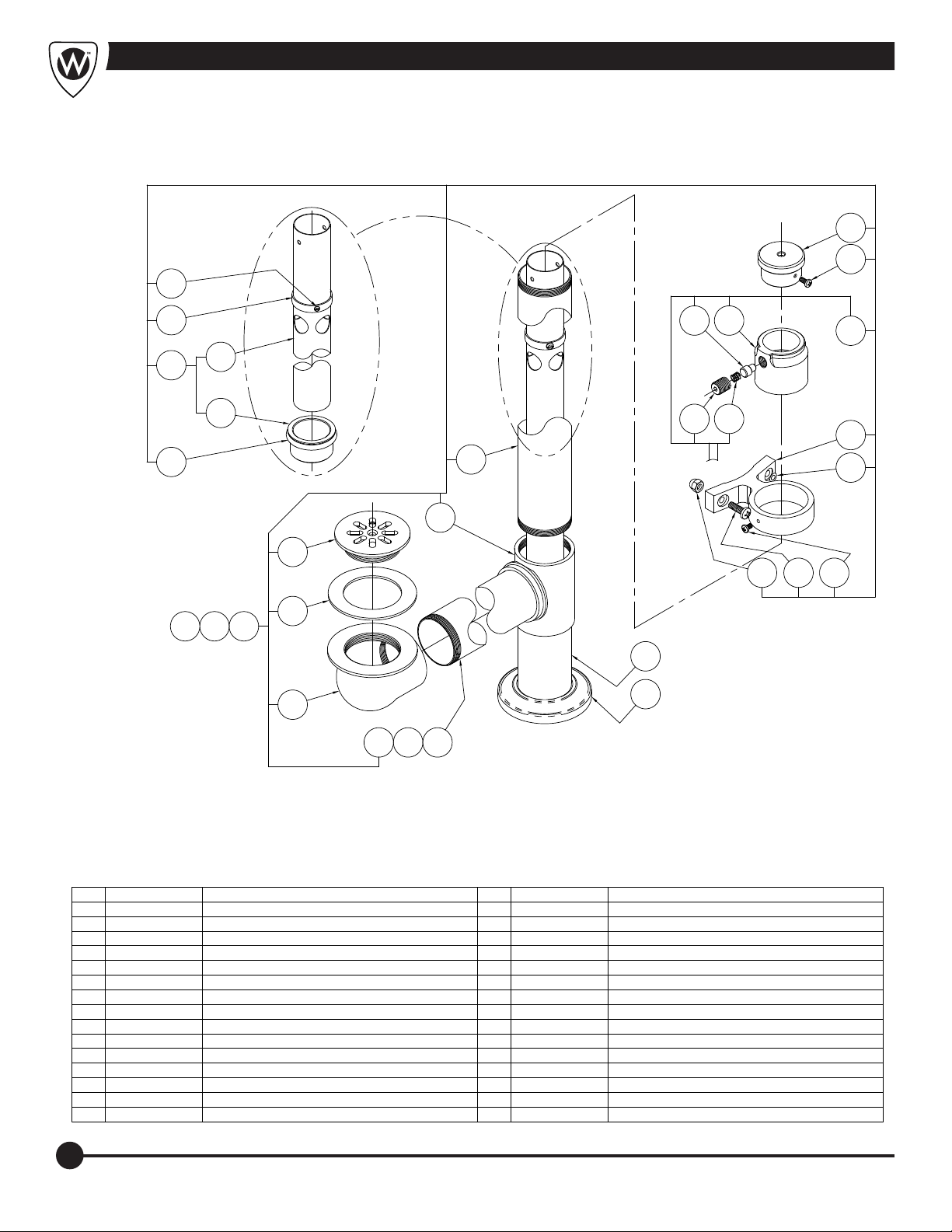
Drain / Overflow Assembly - Lo-Boy
10
9
10
23
24
8
26
25
1A 1B 1C
19
20
11
2122
12
7
13
6
5
1416 15
4
17
3
2C
2B2A
18
ITEM PART NUMBER DESCRIPTION ITEM PART NUMBER DESCRIPTION
1A 6531-024-001
1B 6531-023-001
1C 6531-022-001
2A 6509-380-199
2B 6509-390-199
2C 6509-395-199
3 6508-000-199
4 6504-500-000
5 6508-050-199
6 6508-010-199
7 6509-340-199
8 6531-052-001
9 6531-102-199
10 6502-450-000
11 6531-110-001
DRAIN & OVERFLOW ASSEMBLY - L-75-S
DRAIN & OVERFLOW ASSEMBLY - L-90-S
DRAIN & OVERFLOW ASSEMBLY - L-105-S
2" O.D. x 25-3/8" DRAIN TUBE - L-75-S
2" O.D. x 29-1/4" DRAIN TUBE - L-90-S
2" O.D. x 32-3/8" DRAIN TUBE - L-105-S
DRAIN ELBOW
DRAIN GASKET
STRAINER
DRAIN TEE
2" O.D. x 17" DRAIN TUBE - L-75/90/105-S
22-1/2" OVERFLOW ASSEMBLY
HANDLE
#8-32 x 3/8" PHILLIPS PAN HEAD SCREW
FRICTION LOCK ASSEMBLY
12 6531-100-199
13 0337-050-000
14 6502-103-000
15 6502-200-000
16 6502-500-000
17 6509-405-199
18 6531-104-000
19 6531-110-199
20 6531-111-199
21 6531-113-199
22 6531-112-199
23 6531-101-199
24 6509-065-199
25 6504-221-000
26 6531-103-199
OVERFLOW BRACE
1/4" HELICAL STAINLESS STEEL LOCKWASHER
#8-32 x 1/4" PHILLIPS PAN HEAD SCREW
1/4"-20 x 5/8" PHILLIPS TRUSS HEAD SCREW
1/4"-20 ACORN NUT
2" O.D. x 5" DRAIN TUBE
ESCUTCHEON
FRICTION LOCK HOUSING
FRICTION LOCK ROD
SPRING
TENSION ADAPTER
COLLAR (UP-STOP)
22-1/2" OVERFLOW TUBE
O-RING
O-RING COUPLING
20
Page 23
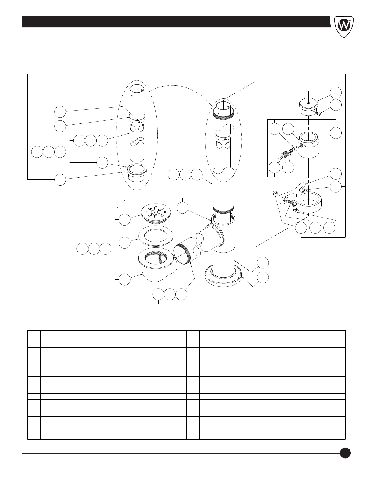
10
Drain / Overflow Assembly - Podiatry Series
9
10
8A
8B
23
8C
25
24A
24B
1A 1B 1C
24C
26
19
20
11
2122
2C
7A
7B
12
13
6
5
1416 15
4
17
3
2C
2B2A
18
ITEM PART NUMBER DESCRIPTION ITEM PART NUMBER DESCRIPTION
1A 6531-021-001 DRAIN & OVERFLOW ASSEMBLY - P-10-S
1B 6531-020-001 DRAIN & OVERFLOW ASSEMBLY - E/P-15-S
1C 6531-019-001 DRAIN & OVERFLOW ASSEMBLY - E/P-22-S
2A 6509-311-199 2" O.D. x 10-3/4" DRAIN TUBE - P-10-S
2B 6509-321-199 2" O.D. x 12" DRAIN TUBE - E/P-15-S
2C 6509-330-199 2" O.D. x 14" DRAIN TUBE - E/P-22-S
3 6508-000-199 DRAIN ELBOW
4 6504-500-000 DRAIN GASKET
5 6508-050-199 STRAINER
6 6508-010-199 DRAIN TEE
7A 6509-320-199 2" O.D. x 11-1/2" DRAIN TUBE - P-10-S
7B 6509-340-199 2" O.D. x 17" DRAIN TUBE - E/P-22-S
8A 6531-050-001 17" OVERFLOW ASSEMBLY - P-10-S
8B 6531-051-001 19-3/4" OVERFLOW ASSEMBLY - E/P-15-S
8C 6531-052-001 22-1/2" OVERFLOW ASSEMBLY - E/P-22-S
9 6531-102-199 HANDLE
10 6502-450-000 #8-32 x 3/8" PHILLIPS PAN HEAD SCREW
11 6531-110-001 FRICTION LOCK ASSEMBLY
12 6531-100-199 OVERFLOW BRACE
13 0337-050-000 1/4" STAINLESS STEEL HELICAL LOCKWASHER
14 6502-103-000 #8-32 x 1/4" PHILLIPS PAN HEAD SCREW
15 6502-200-000 1/4"-20 x 5/8" PHILLIPS TRUSS HEAD SCREW
16 6502-520-000 1/4"-20 ACORN NUT
17 6509-405-199 2" x 5" DRAIN TUBE
18 6531-104-000 ESCUTCHEON
19 6531-110-199 FRICTION LOCK HOUSING
20 6531-111-199 FRICTION LOCK ROD
21 6531-113-000 SPRING
22 6531-112-199 TENSION ADAPTER
23 6531-101-199 COLLAR (UP-STOP)
24A 6509-055-199 17" OVERFLOW - P-10-S
24B 6509-060-199 19-3/4" OVERFLOW - E/P-15-S
24C 6509-065-199 22-1/2" OVERFLOW - E/P-22-S
25 6504-221-000 O-RING
26 6531-103-199 O-RING COUPLING
21
Page 24
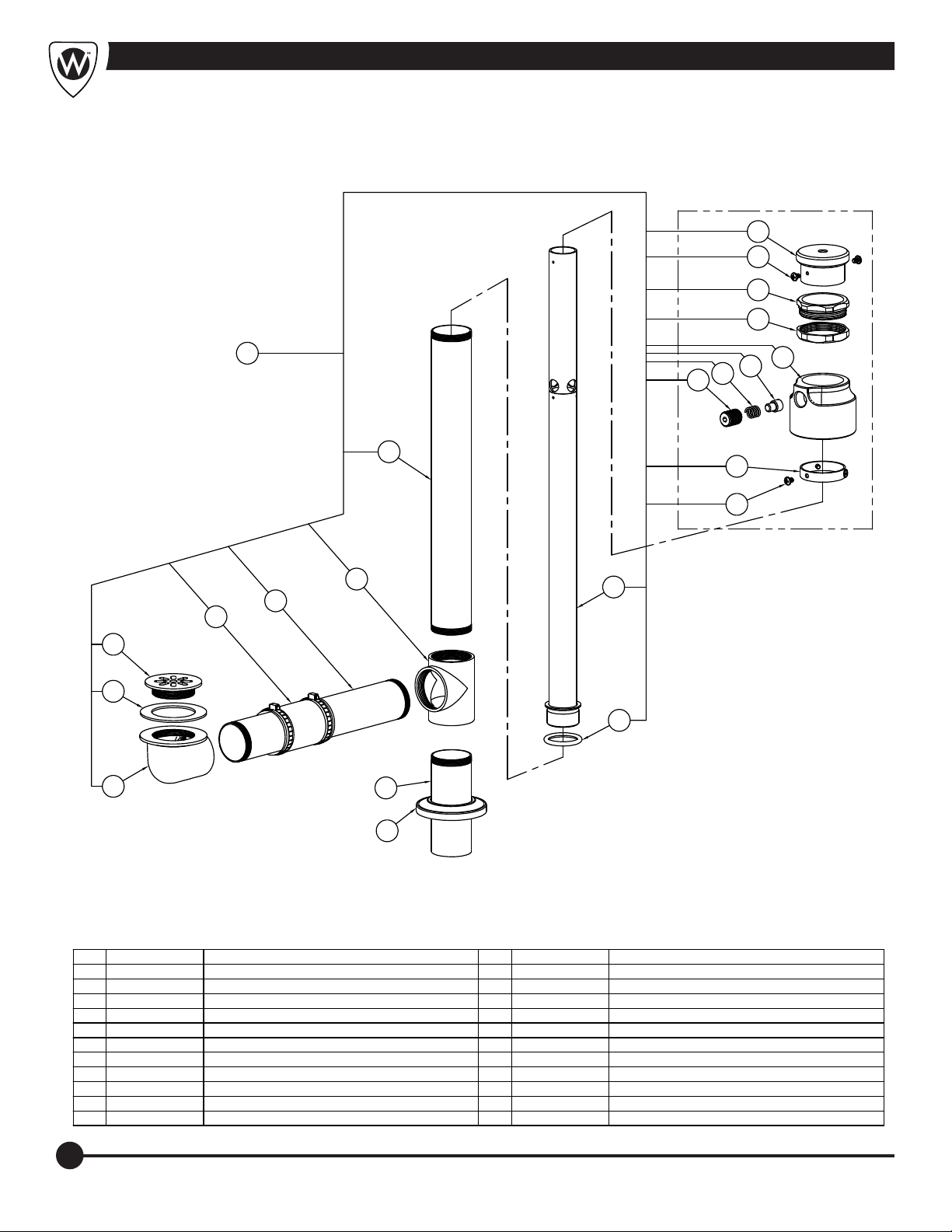
Drain / Overflow Assembly - Slant Back
9
10
11
12
1
15
16
14
13
8
17
10
SCALED x 1-1/4
7
18
6
5
4
3
19
2
20
21
ITEM PART NUMBER DESCRIPTION ITEM PART NUMBER DESCRIPTION
1 WHR00050-001 DRAIN & OVERFLOW ASSEMBLY
2 6508-000-199 DRAIN ELBOW
3 6504-500-000 DRAIN GASKET
4 6508-050-199 STRAINER
5 4995-040-000 1-1/2" x 1-1/2" COUPLING
6 6509-320-199 2" O.D. x 11-1/2" DRAIN TUBE
7 6508-010-199 DRAIN TEE 18 WHR00047-001 23-3/8" OVERFLOW TUBE ASSEMBLY
8 6509-335-199 2" O.D. x 15-1/2" DRAIN TUBE 19 6504-221-000 O-RING
9 6531-102-199 HANDLE
10 6502-450-000 #6-32 x 3/16" PHILLIPS PAN HEAD SCREW 6531-104-000 ESCUTCHEON
11 WHR00049-199 GROMMET GUIDE
12 WHR00057-199 GROMMET GUIDE NUT
13 6531-110-199 FRICTION LOCK HOUSING
14 6531-111-199 FRICTION LOCK ROD
15 6531-113-000 SPRING
16 6531-112-199 TENSION ADJUSTER
17 6531-101-199 COLLAR (UPSTOP OVERFLOW)
6509-405-199 2" O.D. x 5" DRAIN TUBE
20
21
22
Page 25
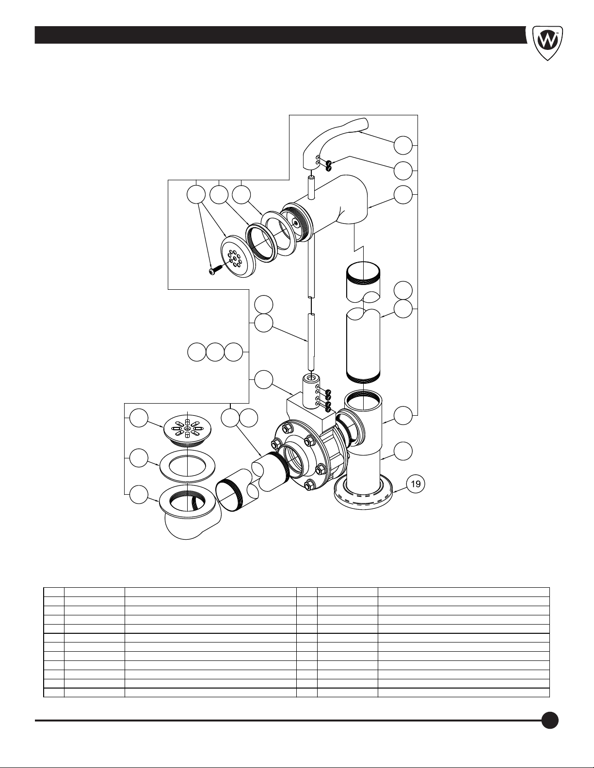
Separate Drain / Overflow Assembly - P-10, P/E-15/22
12
13
9
10
11
14
15
8
16
7
1B 1C1A
6
4
5A
5B
3
17
18
2
ITEM PART NUMBER DESCRIPTION ITEM PART NUMBER DESCRIPTION
1A 6531-200-001 SEPARATE DRAIN OVERFLOW - P-10-S
1B 6531-205-001 SEPARATE DRAIN OVERFLOW - P/E-15-S
1C 6531-210-001 SEPARATE DRAIN OVERFLOW - P/E-22-S
2 6508-000-199 FLOOR PAN DRAIN ELBOW
3 6504-500-000 DRAIN GASKET
4 6508-050-199 STRAINER
5A 6531-400-199 2" O.D. ANGLED DRAIN TUBE - P-10-S
5B 6531-405-199 2" O.D. ANGLED DRAIN TUBE - P/E-15/22-S
6 6531-325-001 DRAIN VALVE ASSEMBLY
7 6509-600-199 DRAIN ROD - P-10-S, P/E-15-S
8 6509-601-199 DRAIN ROD - P/E-22-S
9 6531-330-000 STRAINER ASSY - FOR -SDO & BURN TANKS
10 6531-331-199 LOCK RING
11 6504-507-000 TUB WALL ELBOW GASKET
12 6531-333-199 DRAIN HANDLE
13 6502-402-000 5/16"-18 x 1/4" HEX SOCKET SET SCREW
14 6531-310-199 UPPER DRAIN ELBOW
15 6509-308-199 2" O.D. x 9-1/8" TUBE - P-10-S, P/E-15-S
16 6509-335-199 2" O.D. x 15-1/2" TUBE - P/E-22-S
17 6508-010-199 DRAIN TEE
18 6509-405-199 2" O.D. x 5" DRAIN TUBE
19 6531-104-000 ESCUTCHEON
23
Page 26
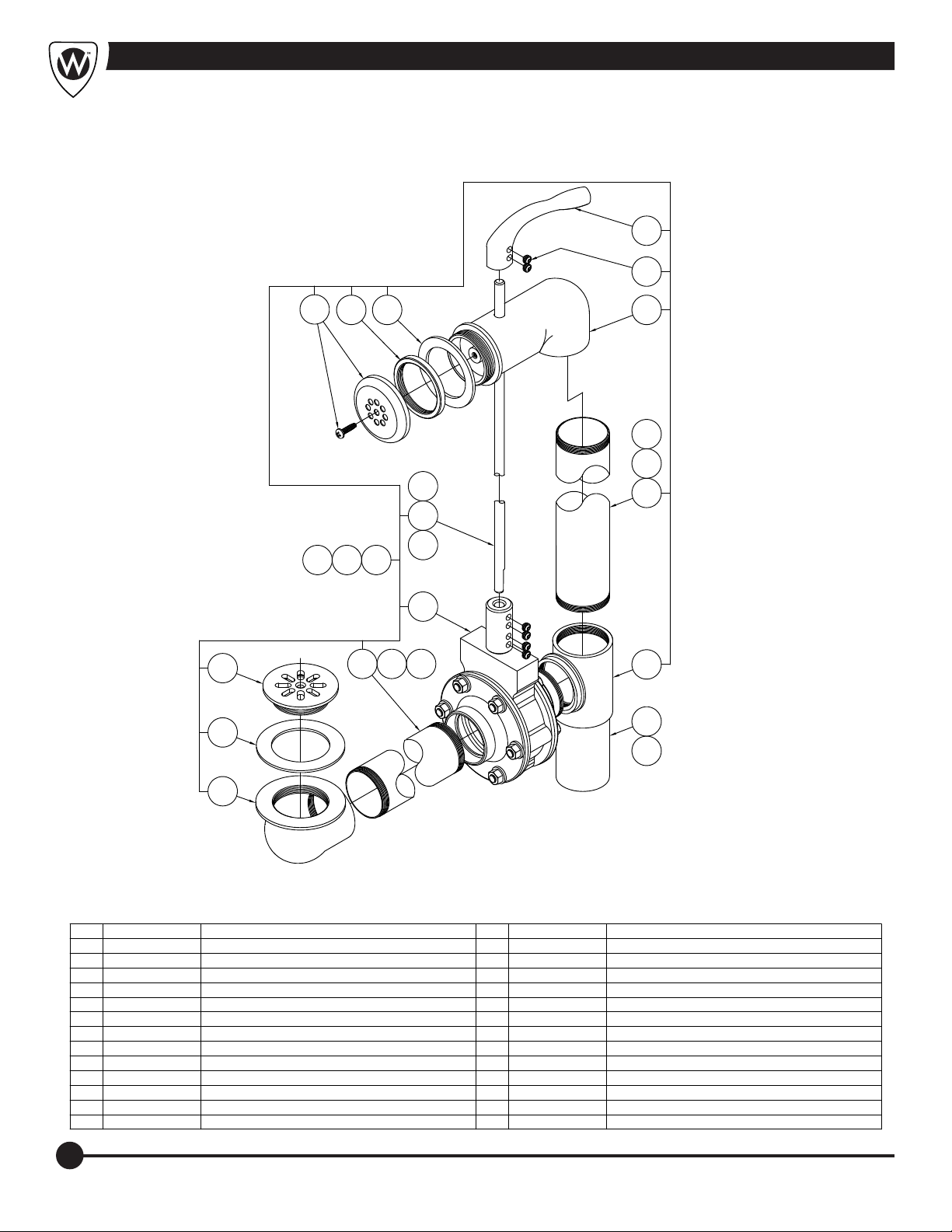
Separate Drain / Overflow Assembly - E-22-SP, E27/24
11
12
8
10
9
13
14A
14B
7A
14C
7B
7C
1A 1C1B
6
5A
4
5B 5C
3
15
16
17
2
ITEM PART NUMBER DESCRIPTION ITEM PART NUMBER DESCRIPTION
1A 6531-215-001 SEPARATE DRAIN OVERFLOW - E-22-SP
1B 6531-220-001 SEPARATE DRAIN OVERFLOW - E-27-S
1C 6531-225-001 SEPARATE DRAIN OVERFLOW - E-45-S
2 6508-000-199 DRAIN ELBOW FOR FLOOR PAN
3 6504-500-000 DRAIN GASKET
4 6508-050-199 STRAINER
5A 6531-403-199 2" O.D. x 6-5/8" DRAIN TUBE - E-22-SP
5B 6531-405-199 2" O.D. x 12-3/8" DRAIN TUBE - E-27-S
5C 6531-331-199 2" O.D. x 14-1/4" DRAIN TUBE - E-45-S
6 6531-325-001 DRAIN VALVE ASSEMBLY
7A 6509-602-199 DRAIN ROD - E-22-SP
7B 6509-603-199 DRAIN ROD - E-27-S
7C 6509-604-199 DRAIN ROD - E-45-S
8 6531-330-000 STRAINER FOR -SDO & BURN TANK ASSEMBLIES
9 6531-331-199 LOCK RING
10 6504-507-000 ELBOW GASKET FOR TUB WALL
11 6531-333-199 DRAIN HANDLE
12 6502-402-000 5/16"-18 x 1/4" HEX SOCKET SET SCREW
13 6531-310-199 UPPER DRAIN ELBOW
14A 6509-338-199 2" O.D. x 15-1/2" DRAIN TUBE - E-22-SP
14B 6509-348-199 2" O.D. x 18-1/8" DRAIN TUBE - E-27-S
14C 6509-363-199 2" O.D. x 22-3/8" DRAIN TUBE - E-45-S
15 6508-010-199 DRAIN TEE
16 6509-435-199 2" EXTENSION TUBE - E-22-SP
17 6509-405-199 2" EXTENSION TUBE - ALL OTHERS
24
Page 27
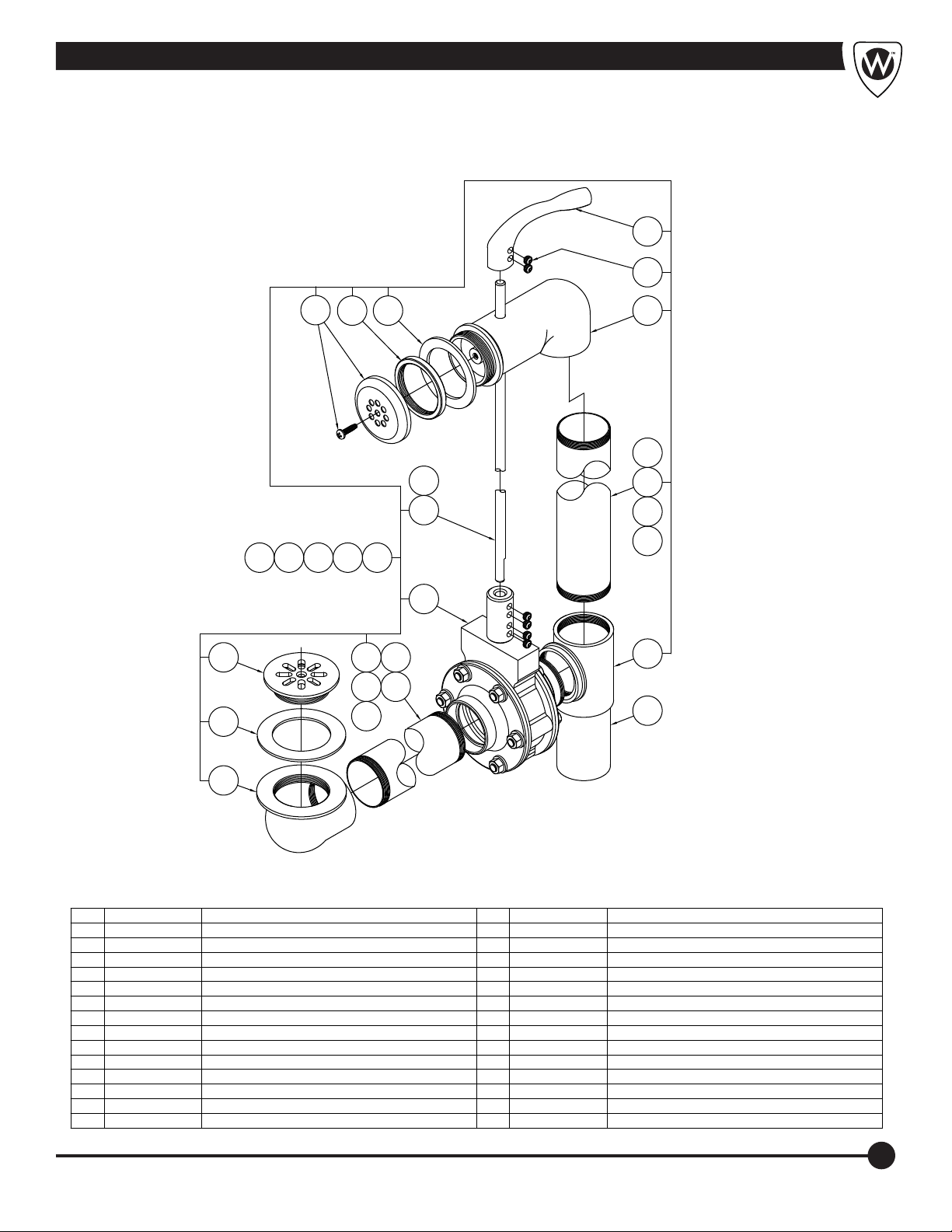
Separate Drain / Overflow Assembly - H60/70/90, S85/90
12
13
4
3
1A 1C1B
9
10
1D 1E
5A
5C 5D
5E
11
5B
14
15
8
7
16
17
18
6
19
20
2
ITEM PART NUMBER DESCRIPTION ITEM PART NUMBER DESCRIPTION
1A 6531-230-001 SEPARATE DRAIN OVERFLOW - H-60-S
1B 6531-235-001 SEPARATE DRAIN OVERFLOW - H-75-S
1C 6531-250-001 SEPARATE DRAIN OVERFLOW - H-90-S
1D 6531-245-001 SEPARATE DRAIN OVERFLOW - S-85-S
1E 6531-240-001 SEPARATE DRAIN OVERFLOW - S-90-S
2 6508-000-199 DRAIN ELBOW FOR FLOOR PAN
3 6504-500-000 DRAIN GASKET
4 6508-050-199 STRAINER
5A 6509-338-199 2" O.D. x 15-15/32" DRAIN TUBE - H-60-S
5B 6531-406-199 2" O.D. ANGLED DRAIN TUBE - H-75-S
5C 6531-409-199 2" O.D. ANGLED DRAIN TUBE - H-90-S
5D 6531-408-199 2" O.D. ANGLED DRAIN TUBE - S-85-S
5E 6531-407-199 2" O.D. x 21-1/4" DRAIN TUBE - S-90-S
6 6531-325-001 DRAIN VALVE ASSEMBLY
7 6509-605-199 DRAIN ROD - H-60/75/90-S
8 6509-604-199 DRAIN ROD - S-85/90-S
9 6531-330-000 STRAINER FOR -SDO & BURN TANK ASSEMBLIES
10 6531-331-199 LOCK RING
11 6504-507-000 ELBOW GASKET FOR TUB WALL
12 6531-333-111 DRAIN HANDLE
13 6502-402-000 5/16"-18 x 1/4" HEX SOCKET SET SCREW
14 6531-310-199 UPPER DRAIN ELBOW
15 6509-380-199 2" O.D. x 25-3/8" DRAIN TUBE - S-60/75-S
16 6509-378-199 2" O.D. x 25-1/8" DRAIN TUBE - H-90-S
17 6509-363-199 2" O.D. x 22-1/8" DRAIN TUBE - S-85-S
18 6509-365-199 2" O.D. x 22-3/8" DRAIN TUBE - S-90-S
19 6508-010-199 DRAIN TEE
20 6509-405-199 2" EXTENSION
25
Page 28
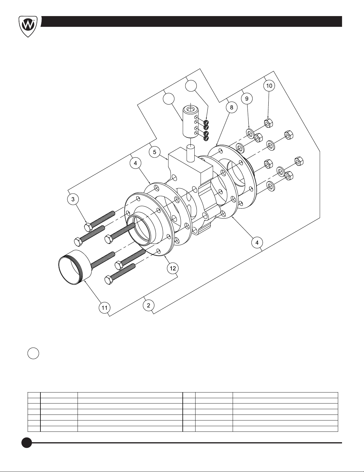
Drain Valve Assembly
7
6
DRAIN VALVE ASSEMBLY1
ITEM PART NUMBER DESCRIPTION ITEM PART NUMBER DESCRIPTION
1 6531-325-001 DRAIN VALVE ASSEMBLY
2 6531-321-001 DRAIN VALVE FLANGE - MALE ASSEMBLY
3 6502-143-000 5/16"-18 x 2-1/4" STAINLESS STEEL HEX HD BOLT
4 6504-506-000 DRAIN VALVE GASKET
5 6531-323-000 WAFER BUTTERFLY VALVE
6 6531-332-199 VALVE COUPLING
7 6502-402-000 5/16"-18 x 1/4" HEX SOCKET SET SCREW
8 6531-320-199 DRAIN VALVE FLANGE - FEMALE
9 6502-563-000 5/16" STAINLESS STEEL HELICAL LOCK WASHER
10 6502-502-000 5/16"-18 HEX NUT
11 6531-322-199 MALE ADAPTER
12 6531-321-199 DRAIN VALVE FLANGE - MALE
26
Page 29
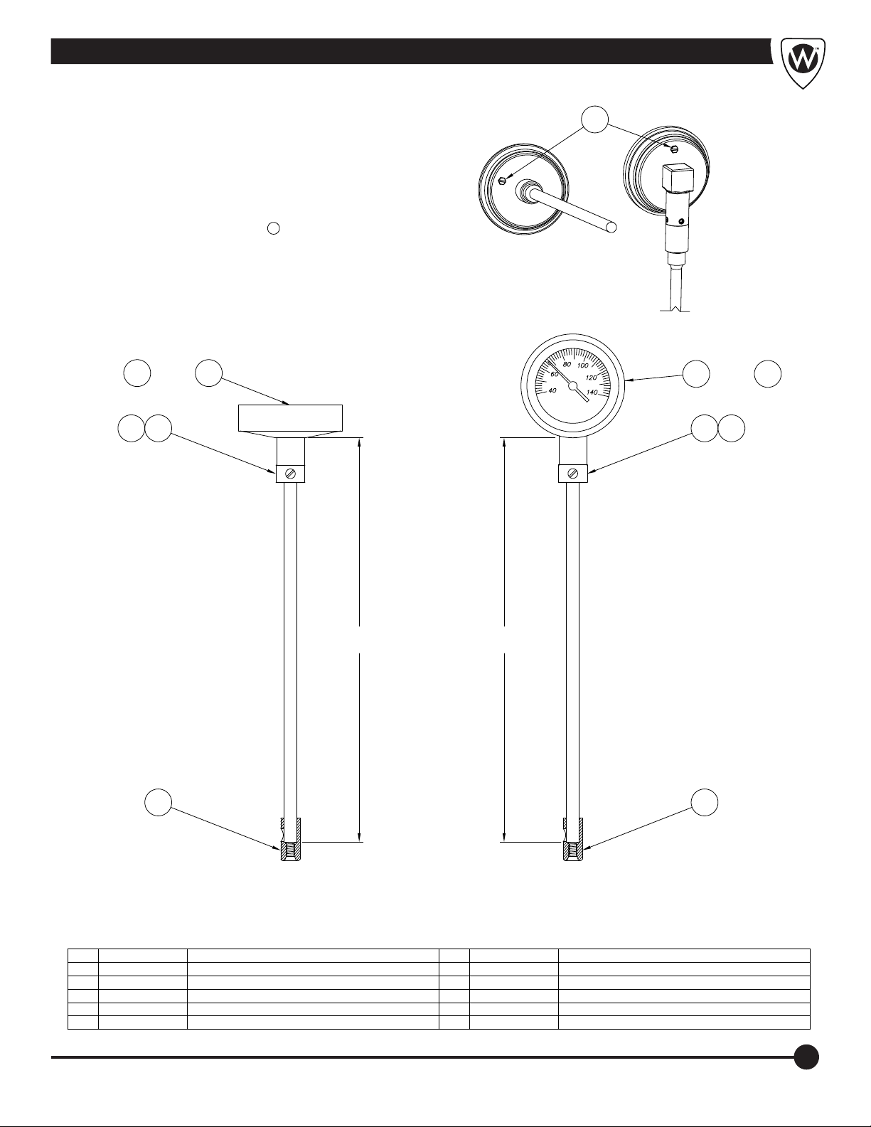
Thermometer
NOTE: THE THERMOMETER GAUGES TEMPERATURES FROM 40°
TO 140° F. DO NOT ALLOW TEMPERATURES TO EXCEED 140° TO
AVOID DAMAGING THE THERMOMETER.
TO RECALIBRATE: IMMERSE THE STEM A MINIMUM OF 4” INTO
THE WATER TURN ON THE TURBINE ASSEMBLY AND ANOTHER
ACCURATE TEMPERATURE GAUGE TO COMPARE AND USE THE
EXTERNAL ADJUSTMENT SCREW PROVIDED ON THE
THERMOMETER CASING AS INDICATED a .
THRU
4
3 43
1C1A
a
THRU
2C2A
LENGTH
IN INCHES
5
BACK CONNECTED
THERMOMETER
AVAILABLE IN 12", 15" & 18" LENGTHS
ITEM PART NUMBER DESCRIPTION ITEM PART NUMBER DESCRIPTION
1A 6532-005-000 BACK CONNECTED THERMOMETER 12"
1B 6532-010-000 BACK CONNECTED THERMOMETER 15"
1C 6532-015-000 BACK CONNECTED THERMOMETER 18"
2A 6532-070-000 BOTTOM CONNECTED THERMOMETER 21"
2B 6532-075-000 BOTTOM CONNECTED THERMOMETER 25"
LENGTH
IN INCHES
5
BOTTOM CONNECTED
THERMOMETER
AVAILABLE IN 21", 25" & LENGTHS
2C 6532-080-000 BOTTOM CONNECTED THERMOMETER 28"
3 6502-451-000 #10-32 x 1/4" PAN HD SLOTTED NYLON SCREW
4 6532-100-199 UPPER THERMOMETER BRACKET
5 6532-101-199 LOWER THERMOMETER BRACKET
27
Page 30
Cleaning and Disinfecting
Cleaning and Disinfecting the Whirlpool
After draining the Whirlpool:
1. Verify that the turbine is OFF.
2. Remove any loose objects or debris that may be
present in whirlpool.
3. To Disinfect:
*Whitehall recommends that you disinfect the
whirlpool after each patient.
*Spray or wipe all surfaces of the whirlpool tank and
thermometer with a hard surface disinfectant,
following the disinfectant manufacturer's instructions.
*Rinse away disinfectant residue with warm, clean
water. If needed (or after the last patient of the day)
wipe the inside and outside surfaces of the whirlpool
with a towel to reduce streaking and spotting.
4. To Clean:
*Clean as needed, or weekly at minimum.
*Hand-wash all surfaces of the whirlpool and
thermometer with a non-abrasive stainless steel
cleaner. Scrub only in the direction of the polish lines
o n the whirl p o o l . F o l l ow th e ma n u f a c t u re ' s
instructions for use.
*Rinse with cold water.
*Wipe inside and outside surfaces with a towel to
reduce streaks and spotting.
Disinfecting and Cleaning of the Turbine
1. Drain the tank.
2. Place an empty bucket beneath the turbine. Fill with
water and add disinfectant solution per manufacturers
recommended use.
3. Turn the control valve to the slow position.
4. Turn on the turbine for 5 seconds and turn it off. Allow
the turbine to soak for a 10 minute contact time.
5. Spray or wipe all exposed surfaces with a mixture of
suitable disinfectant solution per manufacture’s
recommended use. Exposed surfaces should remain
wet for at least 10 minutes.
6. Drain the turbine bucket into the tank and open drain.
7. Rinse all exposed surfaces with warm/hot water.
8. Fill the bucket with water and run turbine for five
seconds to rinse impeller cavity.
The following chemicals are NOT recommended:
Ÿ
Sodium or calcium hypochlorite, chlorines, or
bleach: Chloride ions are a major cause of
stainless steel pitting and are highly caustic and
corrosive. If used, wear skin, eye and respiratory
protection. Immediately rinse off residue.
Ÿ
Phenolics: Phenolics damage metal parts and
plastics and distort the water-lubricated hardrubber bearing in turbine. DO NOT USE.
Ÿ
Glutaraldehydes: These chemicals are good
disinfectants but poor cleaners. Exposure to
vapors is harmful. DO NOT USE.
Ÿ
Iodines: Iodines are good disinfectants but poor
cleaners. Iodines corrode metal surfaces
including stainless steel. If used wear respiratory
protection. Immediately rinse off residue.
Ÿ
Alcohol: Alcohol-based cleaners have limited
effectiveness against some common
microorganisms. They are also extremely
flammable and corrosive. DO NOT USE.
Using abrasive compounds or applicators can
damage the whirlpool's appearance. Do not use
abrasive materials to clean the whirlpool.
Important
Important
*Whitehall recommends the use of Hydrochlor® Whirlpool Antiseptic with all patient treatments.
This simplifies cleaning of equipment by eliminating need for repeated rinsing and scrubbing.
28
Page 31
Care and Cleaning
CARE AND CLEANING OF STAINLESS STEEL
NORMAL CLEANING
Clean weekly or more often, as needed (especially
high-polish surfaces)
RECOMMENDED CLEANING MATERIALS
Ÿ
Sponge - natural or artificial
Ÿ
Nylon or other soft-bristle material brush
Ÿ
SOFT cloth (as used on automobile finishes)
RECOMMENDED CLEANING SOLUTIONS
Ÿ
Hand dishwashing liquid/soft water solution
Ÿ
Mild soap/soft water solution
Ÿ
3M Stainless Steel Cleaner/Polish
Ÿ
White vinegar/soft water solution (for brightening,
removing oil deposit and hard water deposits)
Ÿ
CLR Brand Cleaner or baking soda /soft water solution
(for brightening, removing hard water deposits)
Ÿ
Club soda and sponge
To remove smudges and fingerprints:
Wipe surfaces with a quality Stainless Steel Cleaner /
Polish. Apply using a soft non-abrasive cloth. Always follow
cleaner/polish product directions provided.
To remove dirt and debris:
Wash surfaces with a mild liquid soap. Apply using a soft,
non-abrasive cloth. Rinse surfaces thoroughly with clean
water. Afterwards, using a soft non-abrasive cloth, wipe
surfaces with stainless steel cleaner/polish.
To remove stubborn spots or to treat a scratch
(Standard Satin Finish only): Continued:
CAREFULLY rub out spot with cleaner/polish. Be sure to
rub in the direction of the grain! Do not allow steel wool to
come in contact with stainless steel. Steel particles can
embed into the stainless steel surface and create rust!
Special Note: After cleaning for serious problems, let
dry, and expose to air for at least 24 hours to allow
"healing" (restoring of the chromium oxide layer) of
the stainless steel surface.
FOR ENVIRO-GLAZE STAINLESS STEEL
Protecting the powder coated surface in
keeping an Whitehall Enviro-Glazed stainless steel product
clean and under warranty.
Ÿ
For normal wipe-down cleaning, a mild soap and a
sponge or cotton cloth will perform well.
Ÿ
Ordinary mild cleaners for home use will sanitize the
fixture. (eg. Soft-Scrub , Comet Soft Cleanser Clorox ,
Scrubbing Bubbles Gel.)
Ÿ
NEVER use harsh cleansers such as "Kaboom , Lysol
Gel, Lysol Cling or "The Works" as these contain
® ®, ®
®
®
powerful acidic or alkaline chemicals which may damage
the finish or even the metal of the tank itself. Use of such
chemicals will void the warranty.
Ÿ
NEVER use a metal brush while cleaning. The use of
such a tool at any time will scratch the finish and
perhaps cause corrosion, voiding the warranty.
is the major key
®" ®
To remove rust stains:
Wipe surfaces with CRES (available through Whitehall) or
equivalent cleaner. Use recommended solutions. Apply
using a soft non-abrasive sponge. Rinse surfaces
thoroughly immediately after application. Always follow
cleaner product directions provided. Afterwards, using a
soft, non-abrasive cloth, wipe surfaces with stainless steel
cleaner/polish.
FOR TOUGH PROBLEMS
Ÿ CRES Cleaner specifically for rust stains
(Available through Whitehall)
Ÿ Tarn-X for general stains
Ÿ # 7 chrome polish
Ÿ Silver polish
To remove stubborn spots or to treat a scratch
(Standard Satin Finish only):
Use of synthetic, abrasive, general-purpose pads such as
Scotch Brite is recommended. Apply the stainless steel
®
cleaner/polish to the synthetic, abrasive pads and
THINGS TO AVOID
Ÿ
Harsh polishing cleanser (Comet, Bon Ami, etc.)
Ÿ
Harsh chemicals (strong acidic or alkaline materials
such as hydrochloric acid, sodium hydroxide, etc.)
Ÿ
Any abrasive substance (dirt/mud, ceramic items, etc.)
Ÿ
Chlorinated cleansers, sanitizers or bleach of any kind
Ÿ
Steel wool, steel utensils or any object made of steel or
metal, left in contact with stainless surface (hair pins,
paper clips, aerosol cans)
Ÿ
Scotch-Brite type pads on high-polished surfaces
Ÿ
Seawater or excessively hard water
Ÿ
Salt or salty foods allowed to dry on surface
Ÿ
Leaving scratches in metal surface (soil can collect in
these, preventing surface from "healing")
Ÿ
Leaving hard water sitting (evaporating) for extended
periods, allowing mineral deposits to collect.
®
29
Page 32
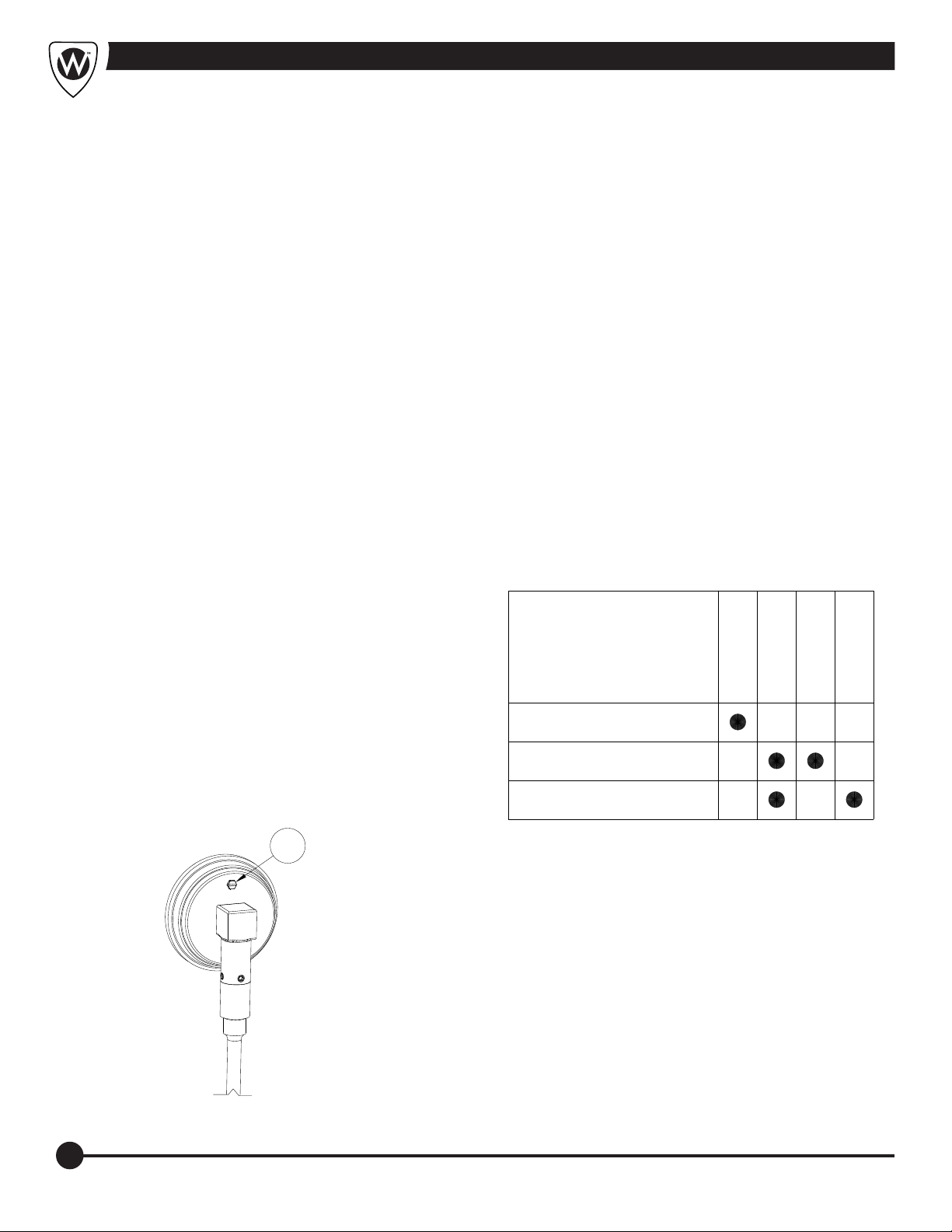
Maintenance and Troubleshooting
Maintenance Schedule
The whirlpool requires regular maintenance. Set up and
follow a maintenance schedule. The table at right
represents minimum intervals for maintenance.
When using m a i n t e na n c e pro d u c t s , fo l l o w the
manufacturers' directions and read the manufacturer’s
MSDS, Material Safety Data Sheets. You can purchase a
recommended disinfectant from Whitehall Customer
Service (Back of Manual) or your Whitehall distributor.
Maintenance Procedures
Motor:
Motors are equipped with sealed greased ball bearings
that do not require lubrication. Vent holes in the motor and
motor cover shell must be cleaned periodically to allow
free air flow and prevent overheating.
Hard Water:
The mineral properties of hard water, if allowed to build up
over a period of time, have the potential for creating
damage to the moving parts of the turbine assembly. We
recommend the installation of a water softener or if that is
not possible, the use of a water softening agent.
Troubleshooting
When there is a significant loss in pressure at the
turbine assembly:
Ÿ Check water inlet holes underneath the pump, clean
away any foreign material.
Ÿ Add water, pump body must be completely submerged.
Motor does not start when switch is turned on:
Ÿ Check your power source.
Ÿ Have a qualified technician check switch.
Motor ceases operation:
Ÿ Check for motor overloads: Possible causes are:
A- Blocked motor ventilation holes
B- Excessive current load
NOTE: The motor is equipped with an overload protector.
In an overheated condition, the motor will automatically
shut off until it has returned to a normal operating
temperature.
Note: The thermometer gauges temperatures from 40° to
140° F. Do not allow temperatures to exceed 140° to avoid
damaging the thermometer.
To recalibrate: Immerse the stem a minimum of 4” into the
water turn on the turbine assembly and another accurate
temperature gauge to compare and use the external
adjustment screw provided a on the thermometer casing
as indicated.
a
Minimum
Maintenance Intervals
Disinfecting (page 17)
Cleaning (page 18)
Inspecting (page 2)
Each Use
As Needed
Each Week
Each Month
30
Page 33
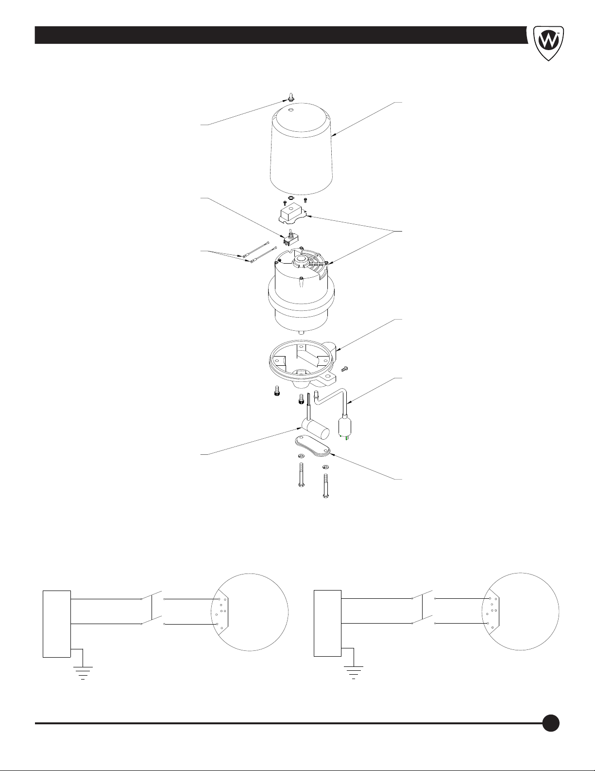
MOTOR DISASSEMBLY
Waterproof Toggle
Switch Cover
Motor Information
Motor Cover
Switch
Wire Connector
Assemblies
Capacitor
Assembly
Motor
Motor Base
Power Cord
Condenser Cover
SWITCH WIRING (115V)
POWER INLET
L
N
BLK
WHT
YEL/GRN
GND
SWITCH
2
X E
1
SWITCH WIRING (230V)
POWER INLET
2
1
6
MOTOR
1
BRN
L
BLU
YEL/GRN
N
GND
SWITCH
2
X E
1
2
1
6
MOTOR
1
31
Page 34

MANUFACTURER'S WARRANTY
Whitehall Manufacturing Company warrants that its products are free from defects in material or workmanship under
normal use and service for a period of one year from date of shipment. Whitehall's liability under this warranty shall be
discharged solely by replacement or repair of defective material, provided Whitehall is notified in writing within one
year from date of shipment, F.O.B. Industry, California.
This warranty does not cover installation or labor charges, and does not apply to materials which have been
damaged by other causes such as mishandling or improper care or abnormal use. The repair or replacement of
the defective materials shall constitute the sole remedy of the Buyer and the sole remedy of Whitehall under this
warranty. Whitehall shall not be liable under any circumstances for incidental, consequential or direct charges caused
by defects in the materials, or any delay in the repair or replacement thereof. This warranty is in lieu of all other
warranties expressed or implied. Product maintenance instructions are issued with each fixture, and disregard or noncompliance with these instructions will constitute an abnormal use condition and void the warranty. If you have any
questions or require technical assistance, please call 800-743-8219.
NOTICE TO KEEP ORIGINAL PACKAGING- Regarding warranty claims: customer must retain original packaging
for one year upon receipt of product. If packaging is discarded, it is the customer's responsibility to provide adequate
packaging. Any shipping claims that are a direct result of customer-provided packaging materials will be handled by
the shipper.
Member of
 Loading...