

Page 1
OWNERS MAN UAL
UD180
Page 2

Owners Name:
Address:
Phone:
Purchase Date:
Purchase Location:
Serial #
: Located on backside of right axle clamp
Steer Tube Length:
Bike Brand:
Frame Size:
Safety
1.) NEVER REMOVE STEER TUBE FROM CROWN. THIS IS A PRESSED IN PART,
REMOVING IT WILL RENDER BOTH CROWN AND STEERER INOPERABLE*.MAKE
SURE YOUR FORK CAPS AND ALL FORK HARDWARE (brake studs,pinch bolts,
etc.) ARE TIGHT
2.) DO NOT PERFORM ANY MODIFICATIONS OR ADJUSTMENTS THAT ARE NOT
OUTLINED IN THIS MANUAL.SEE THE TUNING SECTION OF THE MANUAL FOR
MORE DETAILS.
3.) INSPECT YOUR FORKS BEFORE EVERY RIDE.INSPECT THE CROWN,TUBES AND
AXLE SEAT AREAS FOR ANY SIGNS OF FATIGUE,BENDING,CRACKING OR OTHER
DAMAGE.IF YOU NOTICE ANY TYPE OF DAMAGE,DO NOT RIDE ON THEM.
RETURN THEM TO YOUR DEALER FOR A COMPLETE INSPECTION AND NECESSARY
REPAIR OR WARRANTY STEPS.PLEASE REFER TO THE WARRANTY SECTION OF
THIS MANUAL.
4.) PERFORM ALL RECOMMENDED MAINTENANCE ACCORDING TO THE MAINTENANCE
SECTION OF THIS MANUAL.FAILURE TO PERFORM MAINTENANCE COULD
DRASTICALLY REDUCE YOUR FORKS LIFE AND PERFORMANCE.
5.) WHITE BROTHERS RECOMMENDS THAT YOU WEAR PROPER SAFETY EQUIPMENT
EVERY TIME YOU RIDE,INCLUDING A APPROVED BICYCLE HELMET.NEVER RIDE
AT NIGHT WITHOUT LIGHTS!
* IF SERVICE BECOMES NECESSARY OR REMOVAL OCCURS, PLEASE CALL WHITE BROTHERS CUSTOMER SERVICE
FOR PRODUCT EVALUATION AND DIAGNOSIS.
UD180
Page 3

1
TABLE OF CONTENTS:
SECTION ONE...................Applications..............................................PAGE 1
SECTION TWO
.................Fork Installation.................................PAGE 2 - 3
SECTION THREE
..............Tuning.................................................................PAGE 3 - 4
SECTION FOUR
................Trouble Shooting...............................PAGE 4
SECTION FIVE
...................Maintenance.............................................PAGE 5 - 7
SECTION SIX
......................Exploded View..........................................PA GE 8
SECTION SEVEN
............................Warranty .........................................................PAGE 9
Applications
Thanks for purchasing your new White Brothers Fork. You are in for the best ride of
your life. Our forks are designed to give you the level of performance you need to
ride at your absolute peak.
The White Brothers UD180 fork features a lightweight dual rate coil spring and an
externally adjustable hydraulic damper. This technology is borrowed from motorcy-
cling and offers the best possible suspension action. Steering accuracy is improved
over conventional MTB forks by utilizing dual billet aluminum steering crowns,over-
sized 31.75mm fork tubes,inverted stanchion/slider design and large 20mm axle.
Fork travel has been set at 7” to offer the best performance for downhill racing ter-
rain. A combination coil spring and high-cushion bottom bumper is used to mini-
mize hard bottoming.
Every possible effort has been made to make the White Brothers Fork very light in
weight and perform at a level superior to other forks on the market. To insure peak
performance,proper installation and periodic maintenance is required. Please read
this manual in its entirety to familiarize yourself with the fork and insure your satis-
faction with this product.
White Brothers Forks are designed for offroad use only. They are not equipped with
proper reflectors for on-road use. If you are going to use your forks for road use,
have your dealer or mechanic install reflectors that meet the Consumer Product
Safety Commission’s (C.P.S.C.) requirements for bicycle standards. If you have any
questions concerning C.P.S.C.Standards,please talk to your dealer.
When using your forks on public land and trails,please respect the rights of other
users and stay on established paths and trails. By mounting bik ing responsibly,you
help to insure the future of our sport.
Page 4
1.) Remove old forks from the bicycle. See your bicycle’s owner’s manual. Measure the diameter and length
of your old forks steerer tube to insure that the White Brothers Pro Forx steerer tube is the correct
diameter and has sufficient length for the installation. NOTE:Add .65”(16mm) to length if you are
upgrading from single crown fork to dual crown model.
2.) Remove the crown race from your old forks. NOTE: Replace the
bearings if there are any signs of wear or corrosion.
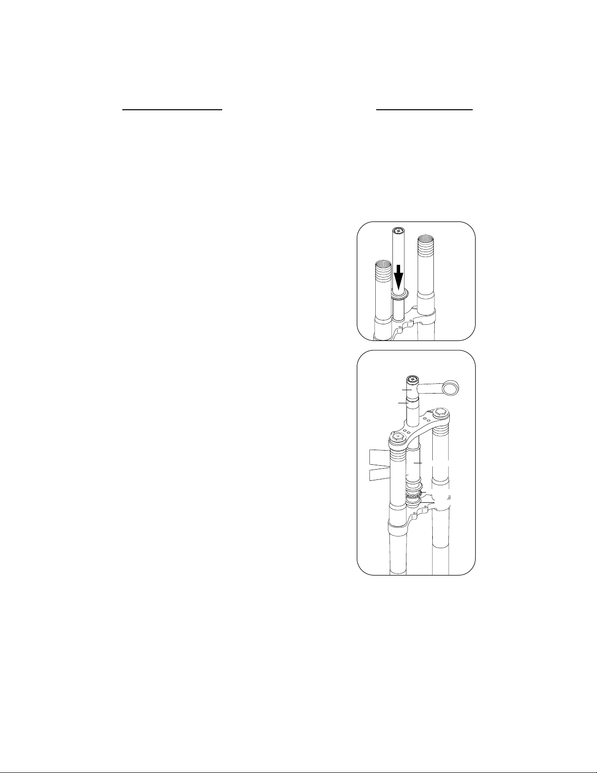
3.) Press the crown race onto the steerer of your White Brothers Fork
(figure 1).
4.) Preassemble headset by sliding fork steerer tube through headset
bearings. Then install top headset,top crown,stem spacer
(optional),and steering stem onto fork steerer tube. Refer to
headset owner’s manual if you have any questions about this
preassembly (figure 2).
5.) Mark steerer tube at top of steerer stem. Steerer must then be cut
3mm (1/8”) below this mark. Consult a dealer or mechanic if you
do not have the proper tools for cutting the steerer tube.
NOTE:The UD180 fork will not work on frames with head tubes
longer than 5 1/2”. See step 11 prior to cutting steerer tube.
NOTE (IF INSTALLING WB MX BAR MOUNTS):Preassemble
headset by: Sliding fork steerer tube through headset bearings. Then install top headset, top crown and 5 to 10mm stem
spacer. Mark steerer tube at top of stem spacer. Steerer must
then be cut 3mm (1/8”) below this mark. Consult a dealer or
mechanic if you do not have the proper tools for cutting the
steerer tube.
6.) The special star fangled nut must now be installed into the steerer.
We recommend dealer installation of this nut since a special tool
is required.
7.) Clean and grease all headset bearings and races to prepare them
for assembly.
8.) Now assemble headset as done in Step 4.
9.) Install the top steering crown.Install the steering stem (threadless
type is required) and handlebars. Set your bars to your desire
height.
10.) Install the threadless mounting cap. Tighten the top threadless
stem bolt until there is no play in the fork tube. The forks should
rotate freely in the head tube. Secure the pinch bolts on the
steering stem. Consult the installation instructions for your
threadless bearing set to insure correct installation and tension
of the headset.
11.) TIRE CLEARANCE:The fork tubes can be adjusted up or down in
the fork crowns to adjust ride height and steering geometry.
NOTE:At full extension of the fork,a minimum of 7 1/2”(190mm) clearance must exist between the tire
and the bottom of the steering crown. NOTE:UD180 Fork has approximately 3/4”negative travel. Pull up
on fork to fully top out fork to make this measurement.
WARNING: Any less clearance than this will allow the tire to contact the bottom of the crown when
the forks are fully compressed. This could stop the wheel from revolving throwing the rider and
causing possible injury or death. Next check to make sure the top of the fork tubes fit all the
way through the top steering crown. If insufficient clearance exists, you must switch to a smaller
diameter front tire. Tighten upper and lower crown pinch bolts to secure fork legs into position.
Fork Installation
White Brothers UD180 Fork features a 1 1/8”threadless steerer tube. If you have a threaded
type fork on your bicycle,consult your dealer for the appropriate upgrade parts
necessary to convert to a 1 1/8” threadless steerer tube.
NOTE: Some frames are not adequately reinforced to handle loads applied by stiffer dual crown
forks. Check with your frame manufacturer to verify dual crown fork compatibility.
2
lower race
steering stem
spacer
(optional)
bicycle head tube
headset bearings
figure 1
figure 2
Page 5

12.) Install your front brakes and adjust following the manufacturers specifications. See additional instructions below. NOTE: Only disc type brakes can be used with the White Brothers UD180 Fork.
13.) RIM CENTERING: S ee your dealer or professional wheel builder to have the rim of your choice laced to
your downhill hub. The wheel builder will need to lace rim so that it is directly centered between the
fork legs,If you are using a 110mm hub you will need to supply your wheel builder with the 10mm
axle spacer (supplied) to achieve correct wheel alignment.
14.) WHEEL/BRAKE INSTALLATION:The White Brothers UD180 Fork is designed for a downhill type hub utilizing a 20mm axle. Install front wheel with disc rotor next to left side of fork. Slide axle all the way
through. Make sure disc rotor doesn’t contact left fork axle seat when axle is tightened fully. If it
does,a custom spacer will have to be fabricated to space hub/rotor away at least 3mm from left fork
axle seat. At this time the brake caliper should be mounted and alignment checked with the disc
rotor. Follow the disc brake manufacturers installation instructions to insure correct brake rotor,
brake caliper alignment.
15.) FINAL WHEEL INSTALLATION: Lightly grease front axle and install front wheel to forks. Tighten axle
completely. Now tighten both left and right fork axle seat pinch bolts. Follow the disc brake manufacturers installation instructions and recommended torque for mounting brake caliper to left fork
leg.
16.) Route hydraulic brake cable up to the brake lever. Make sure that cables is routed so that it cannot
foul on tire,fork crowns,or steering stops through full up and down fork travel and side to side steering radius.
17.) Check to see that your brakes are adjusted and working.
18.) STEERING CLEARANCE: Due to the White Brothers UD180 double crown design,the fork tubes or fork
steering crowns will contact the bicycle frame at full steering lock to the left and right. To eliminate
the chance of damage to the fork or frame,a cushion stop must be fabricated to eliminate metal to
metal contact. Fork bumpers,elastomers or thick pieces of rubber will work fine.Secure in place to
the frame or fork with zip tie or glue. WB offers optional neoprene velcro dual crown fork cushion
stops pn 97-897.
Tuning
To get the most from your White Brothers Pro Forx it is important that you tune the forks to fit your style
of riding and the conditions you ride in.
Initial break-in period
Your new fork is designed to break-in over a period of 10 hours or more of riding. As all of the par ts bed
into each other, the stic tion (friction) of the forks will reduce and the forks will absorb the bumps better.
After this initial break-in,fine tuning the spring preload and cartridge damper may be beneficial to achieve
the best possible fork performance for your weight and riding style.
Tuning Your Springs
There are two ways to adjust your forks. The first is by changing the changing the spring for a completely
different rate. The spring basically controls the quality of the ride. A stiff spring handle major obstacles and
dropoffs better, but doesn’t give as smooth of ride over braking bumps and other small obstacles. Your
White Brothers Fork comes with a Medium rate spring installed. For the majority of riders,this should give
a compliant ride, yet remain resistant to bottoming. If you feel your forks are bottoming too easily, then
switch to the optional spring part # 97-3519.
If forks are too stiff or too soft with either of the springs supplied,WB offers an optional Soft (pn 97-3518)
and X-Heavy Fork Spring (pn 97-3519). Contact your WB dealer to order these.
A fine tuning adjustment for you fork is spring preload. As delivered,the spring preload is correct for most
riders. Spring preload is the amount of pressure that the spring has against it at the full extended position
(spacers are used to adjust spring preload,see items #10 and #11 on the exploded view page). With the correct preload on the spring,with no load on the bike,the forks should come within 3/4”to 1”of returning to
full extension after being compressed. Too much sag,add (1) 2mm or 5mm spacer. Too little sag,remove (1)
2mm spacer. Note if your fork has a build up or an excess of stiction,complete basic service first before preload adjustment.
Fork Installation continued
3
Page 6

A) If your forks rebound too slowly,turn the adjustment screw on
the top of the right fork leg all the way counter-clockwise (6 turns out is the maximum)(figure 3).
The forks should absorb and return fast enough to absorb the next major obstacle. A sign that
your forks are rebounding too slowly is if they feel like they pack-up or continue to compress as
you go through rough sections.
B) If your forks are rebounding too fast,turn the adjustment screw on the top of the right fork leg
clockwise 1/2 turn at a time. A sign of too fast of rebound is if the forks deflect and the bicycle is
hard to hold in lines. The front wheel will also bounce and appear “busy” ie.You get an additional
bounce after landing from a drop. NOTE: If a stiffer spring is installed,your standard setting should
be 1 turn stiffer (clockwise). A light rider that has installed a softer spring will usually be most satisfied with the damping set at the lightest position (6turns out).
Tuning continued
Tuning Your Hydraulic Damper
Adjusting the hydraulic damper should only be done after you
are completely happy with your spring choice,and the proper
spring preload has been set.
Your White Brothers UD180 fork comes with the damping adjusted in the middle of its’range. The standard setting is 3 turns out
from all the way in (clockwise). Use the following guidelines to
determine if further adjustment is needed.
4
Trouble Shooting
Problem: The fork has “stiction”(moves up and down in jerky movements). See Tuning section for
break-in notes
Cause: This is normally caused by lack of lubrication or dirt in the seals and/or bearings,or forks are
not sufficiently broken in
Solution: Clean and lubricate the fork as described in the
maintenance section
Problem: The fork settles too far into its travel
Cause: This is normally caused by a lack of spring preload
Solution: Increase the spring preload
Problem: The fork returns to it’s full height too aggressively,feels like an air fork or “tops out”
Cause: Too much spring preload or (or the hydraulic damper needs serviced)
Solution: Reduce the spring preload or (service hydraulic damper)
Problem: The fork bottoms too easily
Cause: Incorrect spring choice
Solution: Install stiffer option spring and re-adjust damper setting
Problem: The fork doesn’t use it’s full travel
Cause: Incorrect spring choice
Solution: Install softer option spring and re-adjust damper setting
Problem: The fork bounces up and down rapidly
Cause: Insufficient rebound damping
Solution: Increase damping by adjusting by 1/4 turn clockwise.
time (or the hydraulic damper needs serviced)
Problem: The fork has heavy feel,doesn’t return quick enough
for consecutive bumps
Cause: Too much rebound damping
Solution: Decrease damping by adjusting by 1/4 turn counterclockwise.
SLOWER
(cw)
FASTER
(ccw)
figure 3
Page 7

Maintenance
Your White Brothers Fork requires periodic maintenance to insure peak performance and long life. Moisture
and contamination may build up inside the fork. We suggest you disassemble your forks,inspect,clean and regrease them after 30 hours of use. I f the forks appear to be relatively clean,you can probably go 40 hours
between servicing. If the forks appear dirty,you should service them every 20 hours. The three things that will
most effect the service interval and performance of your forks is water,mud and dust. Depending on how
much time you use your forks in those conditions will determine how much service they require.
NOTE:When cleaning the fork, it is not recommended to direct water spray at the seals.
NOTE: Neglecting proper fork maintenance will reduce the forks life. Internal build up of water and dirt,
or a lack of lubrication will cause excessive wear to the forks. In harsh condition it is advisable to
inspect the forks for dirt ingestion after each ride.
Basic service should include disassembly the forks,cleaning and re-greasing all shafts and seals. At this time,
the forks should be carefully inspected for wear and damage before reassembly. NOTE: Disassembly of the
hydraulic damper should be left for a dealer who is familiar with servicing the WB forks hydraulic
damper.
* White Brothers recommends that you consult with a qualified technician before performing the following:
Basic Fork Disassembly
1) Disconnect from brake caliper. Remove wheel assembly by loosening fork axle seat
pinch bolts loosening and removing front axle.
2) Loosen pinch bolts in steering crowns and slide each fork leg down and out of steering
crowns.
RIGHT FORK LEG (DAMPER SIDE) DISASSEMBLY
3) Unthread top fork cap (counterclockwise) utilizing a 25mm (1”) open end wrench or
adjustable wrench. If fork stanchion is clamped in vise during this procedure use jaw
pads to prevent damage to fork. Also avoid excessive clamping force to avoid
crushing fork stanchion(figure 4).
4) Once top fork cap is loosened sufficiently that it is no longer attached to fork stanchion,
grasp lower fork leg at axle seat and compress fork approximately 3”. Loosen damper
shaft from fork cap by securing the shaft in aluminum clamp blocks pn FT180-4 and
turning counter clockwise until cap can be removed from damper shaft (figure 5).
5) Remove spacer tube. Remove outer fork leg from inner leg (figure 6). NOTE: Have pan
under fork to catch small amount of oil that is in fork.Remove 2mm nylon spacer,
auxiliary spring,2mm nylon spacer,coned shaped compression bumper. Leave 5mm
nylon spacer on top of inner fork leg. NOTE: These parts may have stayed in outer
fork leg when removed and will need to be tapped out. No further disassembly is
required on right fork leg unless hydraulic damper is to be serviced.
HYDRAULIC DAMPER SERVICING
NOTE: Disassembly of the hydraulic damper should be left for a dealer who is
familiar with servicing the WB forks hydraulic damper,fur ther special tools are
required.
6.) CAUTION: Damper oil is under pressure, directions for disassembly must be followed
very carefully. ALWAYS WEAR SAFETY GLASSES AND PROTECT YOUR CLOTHES
SHOULD OIL SPRAY OUTWARDS. Fold a thick cloth or shop rag and then fold again
to get 4 layers,place over the end on the shaft. Next hold the rag tightly to the shaft
and gently unscrew the needle holding the end of the shaft down in a drain pan.
This will release the oil pressure in a controlled manner.
Remove 5mm nylon spacer sitting on top of inner fork leg.To remo ve spiral lock cir clip
hold damper shaft assembly into fork,the nylon seal head must be compressed into fork
leg approximately 1mm. Remove circlip by unwinding from groove in a clockwise
manner (a small pick or screwdriver works well for this operation). Grasp damper rod
and lift up slowly.If nylon seal head is reluctant to come out,use aluminum clamp blocks
pn FT180-4 tool to hold damper rod in vise while pulling lightly on fork leg. Remove
nylon seal head and complete damper rod assembly from fork leg.Dump old oil out of
fork leg.Remove damping adjust needle assembly from damping rod by unthreaded
counter clockwise.
figure 4
figure 5
figure 6
5
Page 8

6
and pulling out of damping rod. Inspec t small o’ring on damping adjust needle assembly and replace
if damaged in any way. Also inspect o’ring on nylon seal head and replace if damaged in any way.
NOTE: Readjusting damper shim stack is not recommended. If damping does not meet rider’s
requirements,call the WB suspension service department for recommendations on valving adjustments.
7.) Reassemble hydraulic damper assembly as follows:Place the spiral retainer guide over the inner leg
and Place piston ring guide pn FT180-5 into the retainer guide and Fill with WB RS67 shock oil 3”
(75mm) below the top of the spiral retainer guide. Install damper rod assembly down through both
guides into fork leg and slow compress piston through oil.Stroke the shaft up and down in the oil to
expel air from the damping piston,push the damper shaft down fur ther until oil comes out of the
damper shaft,at this point inser t the needle into the shaf t and screw in until the o-ring is just below the
end of the shaft. Next remove piston ring guide. Then lift the shaft assembly up through the oil while
you are lifting top up oil level to keep the piston submerged in oil,stop with the piston positioned just
below circlip groove,carefully lower the nylon seal head into fork leg. Siphon of excess oil using WB pn
FT180-6. You can then install the seal head and spiral retaining ring in one operation. You should hear
a positive click as the ring enters the groove. NOTE: It may require a tap or two on the seal head tool
to seat the retainer fully home in it’s groove. This operation also charges the system under spring
pressure,stroke damper rod up and down fully to check for smooth damping action and to make sure
damper rod returns to extended position after being compressed. Install 5mm nylon spacer on top of
fork leg.
RIGHT FORK LEG (DAMPER SIDE) ASSEMBLY
8) At this point clean all parts with a clean,non-abrasive rag. A mild grease cutting cleaner or solvent
might make this an easier task.
9) Once clean,inspect seals for tears or cracks. Next, inspect the fork tubes for wear,nicks or scrapes. If
there is noticeable play between fork legs and fork tubes, the DU bushes located inside the outer fork
leg may require replacement. Consult White Brothers or your dealer if servicing or repair is necessary.
10) If everything is free of problems, coat all par ts with a light coating of White Brothers Suspension Lube
or other suitable,non-lithium grease. Also lube the DU bushings that are located inside fork outer leg
by dipping a socket extension in grease and applying the grease into the inside of the fork leg on the
DU bushings.
11) Install oil seals into lip of outer leg,then snap circlip into next lip,then wiper seal.Be careful not to fold
seals (oil seal & wiper seal) when sliding outer leg onto inner leg. Then carefully slide outer fork leg
over inner fork leg making sure not to curl seal lips under during this process. Stroke outer fork leg to
make sure it is sliding smoothly over inner leg.
12) Install 2mm nylon spacer step upward ,cone shaped compression bumper cone down, and auxiliary
spring,Note:The bottomer spacer should be firmly attached to the top cap.
13) Add 20cc’s of 30w motor oil into fork at this time (figure 10). Before threading cap screw adjuster
needle all the way down,thread the fork cap tightly,press in spring
spacer into cap, then stuff o-ring with a flathead screwdriver into
cap. Screw cap onto leg. Stroke fork to check for smooth operation.
Adjust damping needle out as needed once on the bike and you
have ridden it.
LEFT FORK LEG (SPRING SIDE) DISASSEMBLY
1) Unthread top fork cap (counterclockwise) utilizing a 25mm (1”)
open end wrench or adjustable wrench. If fork stanchion is
clamped in vise during this procedure use jaw pads to prevent
damage to fork. Also avoid excessive clamping force to avoid
crushing fork stanchion (figure 4).
2) Once top fork cap is loosened sufficiently that it is no
longer attached to fork stanchion,grasp lower fork leg
at axle seat and compress fork approximately 1”. Loosen
dummy rod from fork cap by inserting 9mm wrench
onto flats of dummy rod and turning counter clockwise
until cap can be removed from dummy rod (figure 7).
figure 7
Page 9

inspect
7
LEFT FORK LEG (SPRING SIDE) ASSEMBLY
6) At this point clean all parts with a clean,non-abrasive rag. A mild
grease cutting cleaner or solvent might make this an easier task.
7) Once clean,inspect seals for tears or cracks. Nex t, inspect the fork
tubes for wear,nicks or scrapes. If there is noticeable play between
fork legs and fork tubes,the DU bushes located inside the upper
fork stanchion may require replacement. Consult White Brothers or
your dealer if servicing or repair is necessary.
8) If everything is free of problems,coat all parts with a light coating of
White Brothers Suspension Lube or other suitable,non-lithium
grease. Also lube the DU bushings that are located inside fork outer
leg by dipping a socket extension in grease and applying the grease
into the inside of the fork leg on the DU bushings.
9) With fork laid over on its side (so dummy rod doesn’t fall into lower
fork leg),install into outer leg oil seal, circlip,and wiper seal.
Then slide outer leg onto inner leg in the vise - Be careful not to fold
seals (oil seal & wiper seal) when sliding outer leg onto inner leg.
10) Then install spring guide seat flat side up,spring guide,spring,and
upper spring seat.
11) Next,thread jam nut loosely (by hand) down until there is 1/2”
(13mm) of exposed thread to engage in top cap. Then install
auxiliary spring.
12) Then thread on cap on to jam nut.Tighten together the cap and
dummy rod by holding the flat sides of dummy rod with 9mm
wrench while rotating cap clockwise.
13) Tip fork up and add 20cc’s of 30w motor oil into fork at this time
(figure 10). Thread fork cap into outer fork leg and tighten fully.
Stroke fork to check for smooth operation. Finish tightening cap with
1”wrench.
14) Reinstall fork legs into fork crowns as instructed in Fork
Installation section.
3) Remove preload spring,auxiliar y spring,jam nut,spring guide dou-
ble,main spring,spring guide,any spring spacers,and spring guide
seat from fork.Remove outer fork leg from inner leg. NOTE: Have
pan under fork to catch small amount of oil that is in fork.
4) To disassemble and inspect negative spring and dummy shaft sys-
tem,remove circlip by unwinding from groove in a clockwise manner (a small pick or screwdriver works well for this operation)(figure 8).
Dummy shaft system with negative spring and bumper can be
removed at this time (figure 9). Inspec t rebound bumper for cracks
or distortion,replace if necessary.
5) Reinstall dummy shaft system into fork leg and install spiral lock cir-
clip by winding back into its groove. Reinstall spring guide seat on
top of inner fork leg.
figure 8
figure 9
figure 10
REQUIRED TOOLS
DESCRIPTION PART #
UD180 SEAL BULLET 1.25" FT180-1
UD180 SPIRAL RET. GUIDE FT180-2
UD180 SHAFT SEAL BULLET FT180-3
UD180 10MM CLAMP BLOCK FT180-4
UD180 PISTON RING GUIDE FT180-5
UD180 SPRL RET. INST/UPR FT180-6-2
UD180 SPRL RET. INST/LWR FT180-6-3
Page 10

1
20
20
50
52
53
54
22
25
46
45
55
56
57
44
43
10
39
38
13
42
27
41
40
37
36
35
34
33
32
31
30
29
28
27
26
4
2
23
24
51
47
49
48
2
3
4
5
6
7
8
9
10
11
12
13
14
15
16
17
18
19
20
21
1
FORK CAP P2351
2
0-RING TOP CAP P3020
3
JAM NUT 97-4100
4
SPRING (AUX.) P3220
5
SPRING GUIDE (DOUBLE) P3300
6
SPRING, UD180 (STD.) 97-3507
7
SPRING, UD180 (OPT) 97-3508
8
SPRING, UD180 (SOFT) 97-3509
9
SPRING GUIDE 97-3557
10
SPACER (5MM) AS REQUIRED 97-3914
11
SPACER (2MM) AS REQUIRED 97-3915
12
SPRING GUIDE SEAT P3320
13
SPIRAL RETAINING RING P4300
14
SPRING CARRIER P3305
15
NEGATIVE SPRING P3208
16
DUMMY ROD P2026
17
REBOUND BUMPER SPACER P3321
18
REBOUND BUMPER 97-3342
19
WASHER, TOP NUT P4100
20
BOLT (M6) 97-852
21
AXLE, UD180 97-3677
22
LEG ASSY. RH UD180 P1511
23
AXLE SPACER, UD180 97-3677-1
24
BOLT, AXLE CLAMP 97-9200
25
LEG ASSY, LH UD180 P1510
26
SPRING (FLOATING PISTON) 97-3500
27
0-RING P3021
28
PISTON (FLOATING) P2010
29
BOLT, DAMPER P4010
30
HIGH SPEED SHIM (20X10X0.15) P2005
31
LOW SPEED SHIM (22X8X0.15) P2006
32
PISTON RING P3000
33
PISTON P2012
34
CHECK VALVE (22X12X0.02) P2004
35
CHECK VALVE SPRING P2015
36
CHECK VALVE GUIDE P2014
37
DAMPER ROD P2025
38
NEEDLE ASSY P2035
39
O-RING NEEDLE 97-1418
40
SPACER, TOP OUT P3335
41
DAMPER SEAL 97-1409
42
SEAL HEAD P2200
43
COMPRESSION BUMPER 97-3341
44
SPRING GUIDE, SINGLE P3301
45
SPRING SPACER P3330
46
FORK CAP P2350
47
UPPER CROWN P1151
48
STAR NUT 1 1/8" 97-9301
49
CROWN ASSY UD180 P1150
50
OUTER LEG, UD 180 P1560
51
DU BEARING 97-986
52
OIL SEAL P3060
53
C-CLIP P4301
54
WIPER SEAL 97-1350
55
DUMMY ROD P2025-1
56
UPPER SHAFT O-RING 97-1416
57
BOTTOMER SPACER P3322
8
The UD180 Exploded View
The following illustration and parts table gives you the exploded view of the UD180DH fork. The parts table lists the part number for each individual part in the fork and is the reference you will need if ordering replacement parts. See your local dealer to order the parts that you require.
Page 11

WARRANTY CLAIMS
White Brothers forks are designed to enhance riding please and as such are
warranted to be free from defects in materials and workmanship for a period of
six months from the date of purchase. On receipt of the forks by White Brothers,
if they are found to be defective, White Brothers will determine replacement or
repair of the forks. This warranty is the sole and exclusive remedy. White
Brothers shall not be liable for any indirect,special or consequential damages.
Warranty does not apply to any product that has been installed improperly or
adjusted using methods not outlined in this manual. Warranty also does not
cover forks that have been misused,or forks that are missing or have altered serial numbers (located on the backside of the right fork stanchion). The forks are
not warranted against damage in the appearance of the fork or for modifications
not outlined in this manual. This warranty does not cover breakage,bending,or
damage that may result from crashes,falls or abuse. Normal wear (i.e.seals,
bushings,slider finish, etc.) and wear and damage caused by lack of proper
maintenance is not included.
A copy of the proof of purchase must be included with all warranties.
Customers in the USA please contact your dealer for a Return Authorization
Number (RA#) before returning the forks. All forks returned for inspection must
be sent freight paid to:
WHITE BROTHERS
A division of EKO Sport Inc.
580 N. Westgate Dr.
Grand Junction, CO 81505
Phone (800) 999-8277 Fax (970) 241-3529
http://www.whitebrotherscycling.com
*Customers outside the USA please contact the dealer or distributor in your area
date service performed
Maintenance Log
date service performed
 Loading...