

Page 1
OWNERS MAN UAL
series
SC72UL#
SC92UL
Page 2

Owners Name:
Address:
Phone:
Purchase Date:
Purchase Location:
Serial #
: Located on backside of right fork leg
Fork Model:
Steer Tube Length:
Bike Brand:
Frame Size:
Safety
1.) NEVER REMOVE STEER TUBE FROM CROWN. THIS IS A PRESSED IN PART,
REMOVING IT WILL RENDER BOTH CROWN AND STEERER INOPERABLE*.MAKE
SURE YOUR FORK CAPS AND ALL FORK HARDWARE (brake studs,pinch bolts,
etc.) ARE TIGHT
2.) DO NOT PERFORM ANY MODIFICATIONS OR ADJUSTMENTS THAT ARE NOT
OUTLINED IN THIS MANUAL.SEE THE TUNING SECTION OF THE MANUAL FOR
MORE DETAILS.
3.) INSPECT YOUR FORKS BEFORE EVERY RIDE.INSPECT THE CROWN,TUBES AND
AXLE SEAT AREAS FOR ANY SIGNS OF FATIGUE,BENDING,CRACKING OR OTHER
DAMAGE.IF YOU NOTICE ANY TYPE OF DAMAGE,DO NOT RIDE ON THEM.
RETURN THEM TO YOUR DEALER FOR A COMPLETE INSPECTION AND NECESSARY
REPAIR OR WARRANTY STEPS.PLEASE REFER TO THE WARRANTY SECTION OF
THIS MANUAL.
4.) PERFORM ALL RECOMMENDED MAINTENANCE ACCORDING TO THE MAINTENANCE
SECTION OF THIS MANUAL.FAILURE TO PERFORM MAINTENANCE COULD
DRASTICALLY REDUCE YOUR FORKS LIFE AND PERFORMANCE.
5.) WHITE BROTHERS RECOMMENDS THAT YOU WEAR PROPER SAFETY EQUIPMENT
EVERY TIME YOU RIDE,INCLUDING A APPROVED BICYCLE HELMET.NEVER RIDE
AT NIGHT WITHOUT LIGHTS!
* IF SERVICE BECOMES NECESSARY OR REMOVAL OCCURS, PLEASE CALL WHITE BROTHERS CUSTOMER SERVICE
FOR PRODUCT EVALUATION AND DIAGNOSIS.
Fork Log
Page 3

1
TABLE OF CONTENTS:
SECTION ONE...................Applications..............................................PAGE 1
SECTION TWO
.................Fork Installation.................................PAGE 2
SECTION THREE
..............Tuning.................................................................PAGE 3-5
SECTION FOUR
................Maintenance.............................................PAGE 6-8
SECTION FIVE
...................Exploded Views...................................PAGE 9-10
SECTION SIX
......................Warranty..........................................................P A GE 13
Applications
Thanks for purchasing your new White Brothers Fork. You are in for the best ride of your
life. Our forks are designed to give you the level of performance you need to ride at your
absolute peak.
The White Brothers Ultra Light Series forks features a lightweight air damper design. This
damper is very easily adjusted for a wide range of riding requirements. Additional tuning can
be accomplished by adjusting negative spring preload or changing the negative springs to a
different style. Steering accuracy is improved over conventional MTB forks by the utilization of
superior materials and design. These include oversized 31.75mm fork tubes,a torsion box
design steering crown with pressed-in tubes (SC72/92UL models),an extruded magnesium
heavy duty brake bridge,and extra-thick machined drop-outs. Fork travel has been chosen to
offer the best performance possible for each forks intended use.
Every possible effort has been made to make the White Brothers Forks very light in weight
and perform at a level superior to other forks on the market. To insure peak performance,
proper installation and periodic maintenance is required. Please read this manual in its entirety to familiarize yourself with the fork and insure your satisfaction with this product.
White Brothers Forks are designed for offr
oad use only. They are not equipped with proper
reflectors for on-road use. If you are going to use your forks for road use,have your dealer or
mechanic install reflectors that meet the Consumer Product Safety Commission’s (C.P.S.C.)
requirements for bicycle standards. If you have any questions concerning C.P.S.C.Standards,
please talk to your dealer.
When using your forks on public land and trails,please respect the rights of other users and
stay on established paths and trails. By mounting biking responsibly,you help to insure the
future of our sport.
Page 4
Fork Installation
White Brothers Ultra Light Series forks features a 1 1/8” threadless steerer tube. If you have a
threaded type fork on your bicycle,consult your dealer for the appropriate upgrade parts nec-
essary to convert to a 1 1/8”threadless steerer tube.
1.) Remove old forks from the bicycle. See your bicycle’s owners manual. Measure the diameter and
length of your old forks steerer tube to insure that the White Brothers fork steerer tube is the correct
diameter and has sufficient length for the installation.
2.) Remove the cr o wn r ac e from your old forks.Note:Replace the bearings if there are any signs of wear
or corrosion
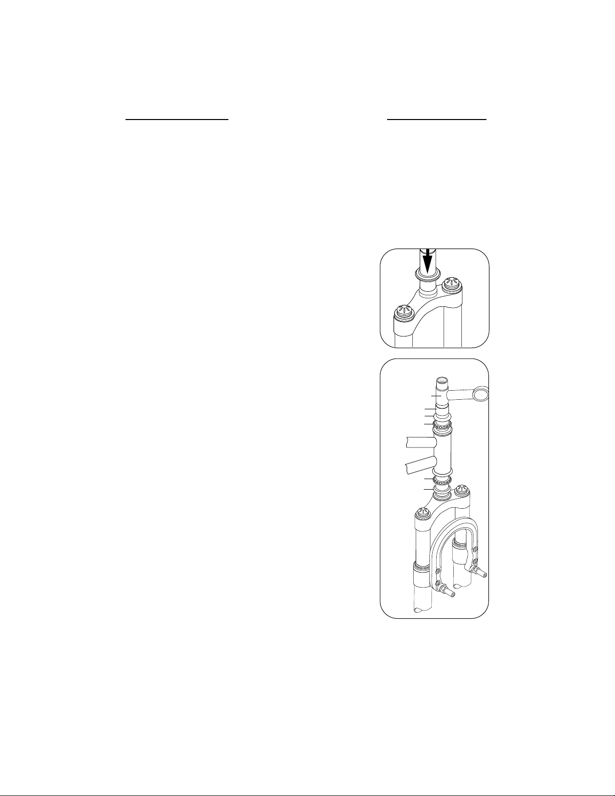
3.) P ress the cro wn rac e onto the steer er of y our White Brothers fork (figure 1).
4.) Preassemble headset by: Sliding fork steerer tube through headset
bearings.Then install top headset, stem spacer (optional),and steering stem onto fork steerer tube. Refer to headset owners manual if
you have any questions about this preassembly.
5.) Mark steerer tube at top of steerer stem. Steerer must then be cut
3mm (1/8”) below this mark. Consult a dealer or mechanic if you do
not have the proper tools for cutting the steerer tube.
6.) The special star fangled nut must now be installed into the steerer.
We recommend dealer installation of this part since a special tool is
required.
7.) Clean and grease all headset bearings and races to prepare them for
assembly.
8.) Now assemble headset as done in Step 4 (figure 2).
9.) Install the steering stem (threadless type is required) and handle-
bars. Set your bars to your desire height.
10.) Install the threadless mounting cap. Tighten the top threadless
stem bolt until there is no play in the fork tube. The forks should
rotate freely in the head tube. S ecure the pinch bolts on the steering stem. Consult the installation instructions for your threadless
bearing set to insure correct installation and tension of the headset.
11.) Install your front brakes and adjust following the manufactures
specifications.
12.) Adjust quick release hub on your front wheel to clear the secondary catches of the forks. The quick release must be tightened after it
is properly seated into the dropout counter bores. Insure that there
is sufficient thread engagement (5 or more threads with the release
adjusted to lock) due to the thicker White Brothers fork dropouts.
Install front wheel to bicycle per manufacturers specification.
13.) Check to see that your br akes are adjusted and w orking.Make
sure brake cable doesn’t foul on any part of bicycle when fork is com-
pressed and released.
2
headset bearings
lower race
top race
steering stem
headset bearings
spacer (optional)
figure 1
figure 2
Page 5

3
Tuning
To get the most from your White Brothers Pro Forx it is important that you tune the forks to fit your style of
riding and the conditions you ride in.
Initial break-in period
Your new fork is designed to break-in over a period of 10 hours or more of riding. As all of the parts bed
into each other, the stic tion (friction) of the forks will reduce and the forks will absorb the bumps better.
After this initial break-in,fine tuning the spring preload and car tridge damper may be beneficial to achieve
the best possible fork performance for your weight and riding style.
Adjustment and Maintenance
.Valve wrench (provided)
.4mm allen wrench
.rear shock pump or other high pressure pump (WB pn 97-725)
.Air Tight Adapter (WB pn 97-726)
.Neutral Shaft Retainer Pin Spanner (WB pn 97-716)
The White Brothers Ultra Light Series forks has been fitted with Total Air cartridges for spring and damping. Total Air cartridges are lightweight, adjustable air-sprung shock absorbers which screw into the fork
stanchions at the crown. The following guidelines for checking and adjusting your cartridges will enable you
to enjoy maximum performance from your fork.
1) IMPORTANT! Always before riding the fork, push down on the bars hard with all your body weight to
check for sufficient air pressure in your Total Air cartridges. The fork should not bottom out easily (if more
pressure is needed,see No.4 through 6 below).
2) Test ride the fork first over easy terrain. If after riding over a variety of terrain you decide that tuning is
necessary,go on to the next section. Before beginning,make sure you have the necessary tools.
Compression Adjustment
3) The compression or overall “spring”of the fork can be changed two ways;by changing air pressure and by
resetting the adjuster. Either change requires re-inflation of the cartridges. Rebound adjustment is done
by changing adjusters.
4) If the forks feels too soft or firm,try changing the air pressure as follows:
SC72UL
Rider Wt.(lbs.) Plush Ride Firm Ride
100-120 110-140 psi 125-150 psi
120-140 130-155 psi 140-160 psi
140-160 140-165 psi 150-170 psi
160-180 150-175 psi 160-180 psi
180-200 160-185 psi 170-190 psi
200-220 170-190 psi 180-200 psi
220- 180-195 psi 190-210 psi
SC92UL
Rider Wt.(lbs.) Plush Ride Firm Ride
100-120 105-110 psi 115-125 psi
120-140 110-125 psi 125-135 psi
140-160 125-140 psi 140-150 psi
160-180 140-155 psi 155-165 psi
180-200 155-165 psi 165-175 psi
200-220 165-170 psi 175-185 psi
220- 170-180 psi 185-195 psi
Page 6

4
5) Unscrew each of the dome-shaped dustcaps so that the schrader valve
stem is exposed
(figure 3).
6) A high pressure shock pump is the best way to inflate cartridges. WB recommend you purchase the BTI High Pressure Air Pump (pn 97-725) and
the BPP Air Tight Adapter (pn 97-726). Install the male part of the BPP Air
Tight Adapter into th ehose end of the BTIHigh Pressure Air Pump. The
pump is ready to use. Thread the pump with adapter onto the fork’s
schrader valve stem(figure 4). Pump the BTI High Pressure Air Pumpuntil
the air pressure is up to pressure recommended on the chart (page 3) for
your weight prefrence and type of fork. Unthread the Air Pump from the
schrader valve stem. Repeat this procedure on the other fork leg. After
pressurizing is completed,reinstall dome-shaped dustcaps.
7) Further tuning can be done by resetting the damping adjuster in each
cartridge. Deflate both cartridges. Brush away any dirt or sand around
the schrader valve and unscrew it with the tubular socket wrench provided. Set the schrader valve aside only on a dust-free surface.
8) The adjuster setting is measured in “turns out”,or counterclockwise turns
from the fully closed position. Your adjusters are preset at 6 turns out.
9) Insert the long end of a 4mm allen wrench through the schrader valve
hole (figure 5). Rotate it slightly while pushing down until you feel it
seat in the top of the adjuster. Turn the wrench clockwise counting the
turns until you reach to fully seated position. NOTE: Do not turn the
adjuster hard clockwise against its seat,only turn it until it lightly touches its closed position. Failure to follow these instructions can damage
the adjuster spring.
10) Now, screw the adjuster counter clockwise to the setting you need.
Fewer “turns out”will result in a firmer ride,more turns out will provide a
plusher ride. The following guidelines may be useful. NOTE:Never set
the adjuster at more than 8 turns out from bottom.
SC72UL
Rider Wt.(lbs.) Plush Medium Firm
100-120 8 6 1/2 5
120-140 7 1/2 6 4 1/2
140-160 7 5 1/2 4
160-180 6 1/2 5 3 1/2
180-200 6 4 1/2 3
200-220 5 1/2 4 2 1/2
220- 5 3 1/2 2
SC92UL
Rider Wt.(lbs.) Plush Medium Firm
100-120 8 7 6
120-140 7 1/2 6 1/2 5 1/2
140-160 7 6 5
160-180 6 1/2 5 1/2 4 1/2
180-200 6 5 4
200-220 5 1/2 4 1/2 3 1/2
220- 5 4 3
11) When replacing the schrader valve in the air cap,make sure that
the o’ring on the schrader valve is free of dust or hair and in good
condition. Warning: Use only the tubular wrench to tighten
the schrader valve;ordinary wrenches or pliers can overstress
the threads in the nylon air cap.
Adjuster
Piston O-Ring
Air Cap O-Ring
Adjuster O-Ring
Compression Valve
Valve Spring
Negative Spring
Spring Spacer
figure 3
figure 4
figure 5
Page 7

5
12) Rebound is governed by the size of a small hole in the adjuster. The
adjusters installed in your cartridges are rated for “medium”
rebound. In the small bag included in the package are adjusters
rated for “slow”and for “fast”rebound damping.
13) Adjusters are coded to distinguish them. Slow rebound adjusters
are marked #1, medium are marked #2, and fast are marked #3
(figure 6).
14) To change an adjuster, deflate both cartridges and remove the
schrader valve stems. Insert the long end of a 4mm allen wrench
through the hole and into the top of the adjuster . Rotate the adjuster
counterclockwise several times until it finally comes loose. When the
adjuster is free,it can be withdrawn on the end of the allen wrench by
tilting the wrench slightly and pulling it up through the valve stem
hole (figure 7). Caution: Just under the adjuster are the compres-
sion valve and spring; these may fall out if the fork is turned
upside-down while the adjuster is out. If they do fall out, first install
the spring, then seat the tapered end of the compression valve in
the adjuster and carefully re-install the adjuster into the cartridge.
15) Insert the new adjuster through the schrader valve hole in the air cap. Follow Steps 9 and
10 for installing and positioning the adjuster.
16) Reinstall the schrader valve,inflate the cartridges and replace the dust cap. The standard
rebound settings should suit most applications when the proper air pressure has been used,
since damping medium increases with pressure.
By increasing or decreasing preload,and/or changing negative springs,the
action of the White Brothers Ultra Light Series forks can be altered. White
Brothers has designed each model of the Ultra Light Series forks to be tuneable for a very plush initial ride or adjusted for a firmer, with less pedal
induced bio-pacing type of ride. Below list the negative spring
tuning options for each fork.
SC72UL: As delivered, the SC72UL fork is equipped with a long negative
spring and guide system (Std.Kit, figure 8) that offers a plush,
responsive initial ride. This system is recommended for most riders. Included
with the SC72UL is the (Pro Kit, figure 9). The Pro Kit consist of a short
negative spring and nylon spacer (replaces the long negative spring and
nylon guide). With the Pro Kit installed, the forks are quite stiff at the top of
the travel. Bobbing while climbing and pedal induced bio-pacing is reduced
with the Pro Kit installed. See figure 8 and 9 for proper installation of the
negative spring system.
SC92UL/DC120UL: As delivered, the SC92 and DC120UL fork is equipped
with a long negative spring and guide system. This system is recommended
for most riders. Optional spacers are included with each fork that will increase
the preload on the negative springs and offer a plusher,more responsive initial
ride. Normally, we recommend installation of these spacers only when the fork pressure has
been adjusted to a very high setting for heavy riders. Install one or three spacers (the more spacers,the softer the initial fork travel) under the negative spring inside the bottom out cap (figure
10). NOTE: Never install more than three spacers under the negative spring,fork travel will
be reduced. See exploded view for proper installation of the negative spring system.
plush
firm
Negative Spring Adjustments
figure 6
figure 7
figure 9
figure 8
Rebound Adjustments
Page 8

Maintenance
Your White Brothers fork requires periodic maintenance to insure peak performance and long
life. Moisture and contamination may build up inside the fork. We suggest you disassemble your
forks,inspect, clean and re-grease them after 30 hours of use. If the forks appear to be relatively
clean,you can probably go 40 hours between servicing. If the forks appear dirty,you should service them every 20 hours. The three things that will most effect the service inter val and per formance of your forks is water,mud and dust. D epending on how much time you use your forks in
those conditions will determine how much service they require.
NOTE: When cleaning the fork,it is not recommended to direct water spray at the seals.
NOTE: Neglecting proper fork maintenance will reduce the forks life. Internal build up of water
and dirt,or a lack of lubrication will cause excessive wear to the forks.
Maintenance (Total Air Cartridges)
1) Check and top up pressure in the cartridges after approximately 10 hours of typical riding
(more often in the case of racing or very hard riding) or if the bike has not been ridden for two
weeks or more. Lubricate the cartridge shaft every two months using WB/Englund
Suspension Lube or Englund Slick Honey.
2) If unusual pressure loss occurs,remove the cartridges,inflate to at least 150 psi and immerse
in water for several minutes with the dust caps removed. Slow bubbling from inside or underneath the air cap usually indicates a contaminated schrader valve o’ring or air cap o’ring.
Remove suspect o’rings with a toothpick. If the o’ring is not cut or torn,cleaning and regreasing the o’ring and o’ring seats will usually repair the leak. Slow bubble formation at the top of
the schrader valve (one bubble every 30-60 minutes) is normal,more rapid bubbling indicates
a loose or defective valve core.
If no leak can be seen after fifteen minutes of immersion,pressure loss probably occurs in use
due to a worn or contaminated cartridge body o’ring. The body o’ring is easy to replace with
a “Cartridge Body Seal Kit”available through your local dealer or from White Brothers.
Disassembly/Assembly Negative Spring System
1) Let air out of Total Air Cartridges by removing dome-shaped dust caps and compressing
valve core.
2) See Basic Fork Disassembly/Assembly for how to remove and reinstall lower fork legs from
fork stanchions.
3) With fork legs removed,loosen nylon bottom out cap from fork stanchion. NOTE:A proper
fitting pin spanner or WB pn 97-716 tool is required. Remove entire dummy shaft assembly
noting order of parts. Adjust negative spring preload and/or spring per Negative Spring
Adjustments above, or simply remove the travel limiter and compression bumper and slide
assembly out the top crown with
cartridges and top caps removed.
4.) To install Pro Kit remove long negative spring and guide. Then install shor t spring and
spacer supplied in kit.
5.) Reinstall in reverse order.
6
Page 9

* White Brothers recommends that you consult with a qualified technician before performing the following:
Basic Fork Disassembly
1) Disconnect front brake and remove wheel as outlined in your
bicycle’s owners manual.
2) Remove allen head bolts at the bottom of the forks using a
6mm allen wrench (figure 1).
3) Simply slide the lower fork legs off the end of the inner stanchion tubes. Be careful not to damage the seals as you pull
inner legs out (figure 2).
4) At this point clean all parts with a clean,non-abrasive rag. A
mild grease cutting cleaner or solvent might make this an
easier task.
Once clean,inspect seals for tears or cracks. If okay,regrease
them with White Brothers Suspension Lube or other suitable,
non-lithium grease. If your seals are no longer serviceable,
check the General Disassembly Parts Table section of this
manual for the proper replacement part numbers. Also,check
carefully the DU bushes for wear. This is done by looking at
the color of the bushes. If they are dark grey, the bushes are
okay. If they are bronze/gold in areas, they are worn and
can cause fork stanchion damage. Your dealer will be able
to order any replacement parts you might need.
5) Next, inspect the fork stanchion tubes for wear, nicks or
scrapes. If there is noticeable play between lower fork legs
and fork stanchions,the DU bushes located inside the lower
fork legs may require replacement. Consult your dealer for
service options.
6) If ever ything is free of problems, coat all parts with a light
coating of White Brothers/Englund Suspension Lube or other
suitable,non-lithium grease. Also lube the DU bushings that
are located inside lower fork legs by dipping a socket extension in grease and applying the grease into the inside of the
fork stanchion on the DU bushings.
READ PRIOR TO FORK ASSEMBLY: White Brothers Ultr a Light
Series forks feature a triple lip seal system with wiper seal.15
cc’s of 30wt. Motor oil is also added through top of fork to
keep fork internals lubricated and reduce maintenance requirements. An optional Slick Kit System is included with each WB Ultra Light Fork. Kit consists of
foam wiper that replaces the triple lip seals installed in the fork legs. The slick kit reduces seal
tension and decreases stiction in the fork. Since the only the foam wipers are oiled,weight
(approx.30 grams) is saved because additional lubricating only is not added to the fork. The
Slick Kit System is recommended for dry conditions and requires more frequent fork
disassembly and maintenance schedules.
7
figure 1
figure 2
Page 10

8
Basic Fork Assembly
7a) WITH STD. TRIPLE LIP SEAL SYSTEM, (figure 3): Install cone
shaped compression bumper and nylon travel limiter (see
parts breakdown drawings on page 8 for correct installation of
these parts). Carefully install fork legs over fork stanchion
tubes rocking legs slightly allowing fork stanchion tubes to
engage DU bushings inside of fork legs. Fully compress f orks so
that 6mm allen bolts can be installed into bottom fork legs and
engage internal rods. NOTE: Do not tap fork legs onto stanchions, DU bushings can be dislodged. Slide both fork stanchions into lower fork legs and fully compress. Fully tighten
6mm allen bolts in lower fork legs. Remove complete Total Air
Cartridges from top of fork legs and add 15cc’s of 30wt motor
oil per side. Reinstall and tighten fully the Total Air Cartridges.
7b) WITH SLICK KIT SYSTEM, (figure 4): Remove the top wiper
seals and triple lip seals (triple lip seals will not be reinstalled)
with a tire tool prying upward. NOTE: Remove top wiper seal
tension spring prior to prying seals upward. Be careful not to
damage seal or scratch aluminum seal housing. Slide fork seals
and Slick Kit foam wipers over both fork stanchion tubes. S eals
should be greased and wipers should be oiled prior to assembly. Install cone shaped compression bumper and nylon travel
limiter (see parts breakdown drawings on pages 8 through 10
for correct installation of these parts). Carefully install fork legs
over fork stanchion tubes rocking legs slightly allowing fork
stanchion tubes to engage DU bushings inside of fork legs.
Fully compress forks so that 6mm allen bolts can be installed
into bottom fork legs and engage internal rods. NOTE: Do not
tap fork legs onto stanchions,DU bushings can be dislodged.
Slide both fork stanchions into lower fork legs and fully compress. Fully tighten 6mm allen bolts in lower fork legs. Slide the
foam ring into each lower fork leg carefully tucking it in on all
sides. Finish reassembly by snapping into place the fork seals
(figure 5).
8) Make sure fork caps and cartridges are fully tightened into top
of fork stanchion tubes. Connect front wheel and brakes as outlined in your bicycles owners manual.
9) Compress your forks to make sure they work smoothly and brake
cable doesn’t foul on fork in anyway.
figure 3
figure 4
figure 5
Page 11

9
7
8
6
5
4
3
2
1
9
10
OPT.
OPT.
STD.
11
31
30
29
28
27
26
25
24
22
21
20
19
15
14
16
17
18
11
23
12
13
1
WIPER SEAL 97-1350
2
FOAM RING 97-1358
3
OIL SEAL P3060
4
DU BUSH 97-986
5
TI BRAKE MOUNT STUD 97-3662
6
BRAKE SPRING RETAINER 97-3663
7
BRACE BOLT (6M) P4001
8
BRACE P1602
9
LEG ASSEMBLY (LH) P1502
10
LEG ASSEMBLY (LH W/ BRAKE MOUNT) P1500
11
SHAFT BOLT(8mm) P4000
12
SEALING WASHER P4000-1
13
LEG ASSEMBLY (RH) P1501
14
1
1/8"
STAR NUT 97-9301
15
AIR DAMPENING SYSTEM (75mm) 97-875
16
TOP FORK CAP 97-3655
17
0-RING P3023
18
CROWN ASSEMBLY P1140
19
COMPRESSION PAD 97-858-30
20
PLUG, PUSHER P2501
21
DUMMY PUSHER '99 P2500
22
0-RING F-2402
23
PRELOAD SHIM (AS REQIURED) P3310-1
24
NEGATIVE SPRING GUIDE P3310
25
NEGATIVE SPRING P3202
26
BOTTOM OUT CAP P3306
27
PRO KIT SPRING P3202-1
28
PRO KIT SPACER P3202-2
29
DUMMY SHAFT P2020
30
COMPRESSION BUMPER P3290
31
TRAVEL LIMITER 97-3900
The SC72ul Exploded View
The following illustration and parts
table gives you the exploded view of
the SC72ul fork. The parts table lists
the part number for each individual
part in the fork and is the reference
you will need if ordering replacement
parts. See your local dealer to order
the parts that you require.
Page 12

10
7
8
6
5
4
3
2
1
9
OPT.
STD.
10
27
26
25
24
23
21
22
20
19
18
14
13
15
16
17
7
11
12
1
WIPER SEAL 97-1350
2
FOAM RING 97-1358
3
OIL SEAL P3060
4
DU BUSH 97-986
5
STEEL BRAKE MOUNT STUD 97-3665
6
BRAKE SPRING RETAINER 97-3663
7
BRACE BOLT (6M) P4001
8
BRACE P1602
9
LEG ASSEMBLY (LH W/ BRAKE MOUNT) P1500
10
11
SHAFT BOLT(8mm) P4000
12
SEALING WASHER P4000-1
13
LEG ASSEMBLY (RH) P1501
14
1
1/8"
STAR NUT 97-9301
15
AIR DAMPENING SYSTEM (95mm) 97-876
16
TOP FORK CAP 97-3655
17
0-RING P3023
18
CROWN ASSEMBLY P1142
19
COMPRESSION PAD 97-858-30
20
PLUG, PUSHER P2501
21
DUMMY PUSHER '99 P2500
22
0-RING F-2402
23
PRELOAD SHIM (AS REQIURED) P3310-1
24
NEGATIVE SPRING GUIDE P3310
25
NEGATIVE SPRING P3203
26
BOTTOM OUT CAP P3306
27
DUMMY SHAFT P2021
COMPRESSION BUMPER P3290
The SC92ul Exploded View
The following illustration and parts
table gives you the exploded view of
the SC92ul fork. The parts table lists
the part number for each individual
part in the fork and is the reference
you will need if ordering replacement
parts. See your local dealer to order
the parts that you require.
Page 13

11
Notes
Page 14

12
date service performed
Maintenance Log
date service performed
Page 15

WARRANTY RETURNS
White Brothers forks are designed to enhance riding please and as such are
warranted to be free from defects in materials and workmanship for a period
of six months from the date of purchase. On receipt of the forks by White
Brothers,if they are found to be defective,White Brothers will determine
replacement or repair of the forks. This warranty is the sole and exclusive remedy. White Brothers shall not be liable for any indirect,special or consequential damages.
Warranty does not apply to any product that has been installed improperly
or adjusted using methods not outlined in this manual. Warranty also does
not cover forks that have been misused,or forks that are missing or have
altered serial numbers (located on the backside of the right fork stanchion).
The forks are not warranted against damage in the appearance of the fork or
for modifications not outlined in this manual. This warranty does not cover
breakage,bending,or damage that may result from crashes,falls or abuse.
Normal wear (i.e.seals,bushings,slider finish, etc.) and wear and damage
caused by lack of proper maintenance is not included.
A copy of the proof of purchase must be included with all warranties.
Customers in the USA please contact your dealer for a Return Authorization
Number (RA#) before returning the forks. All forks returned for inspection
must be sent freight paid to:
WHITE BROTHERS
A division of EKO Sport Inc.
580 N. Westgate Dr.
Grand Junction, CO 81505
Phone (800) 999-8277 Fax (970) 241-3529
http://www.whitebrotherscycling.com
*Customers outside the USA please contact the dealer or distributor in your area
13
 Loading...