

Page 1
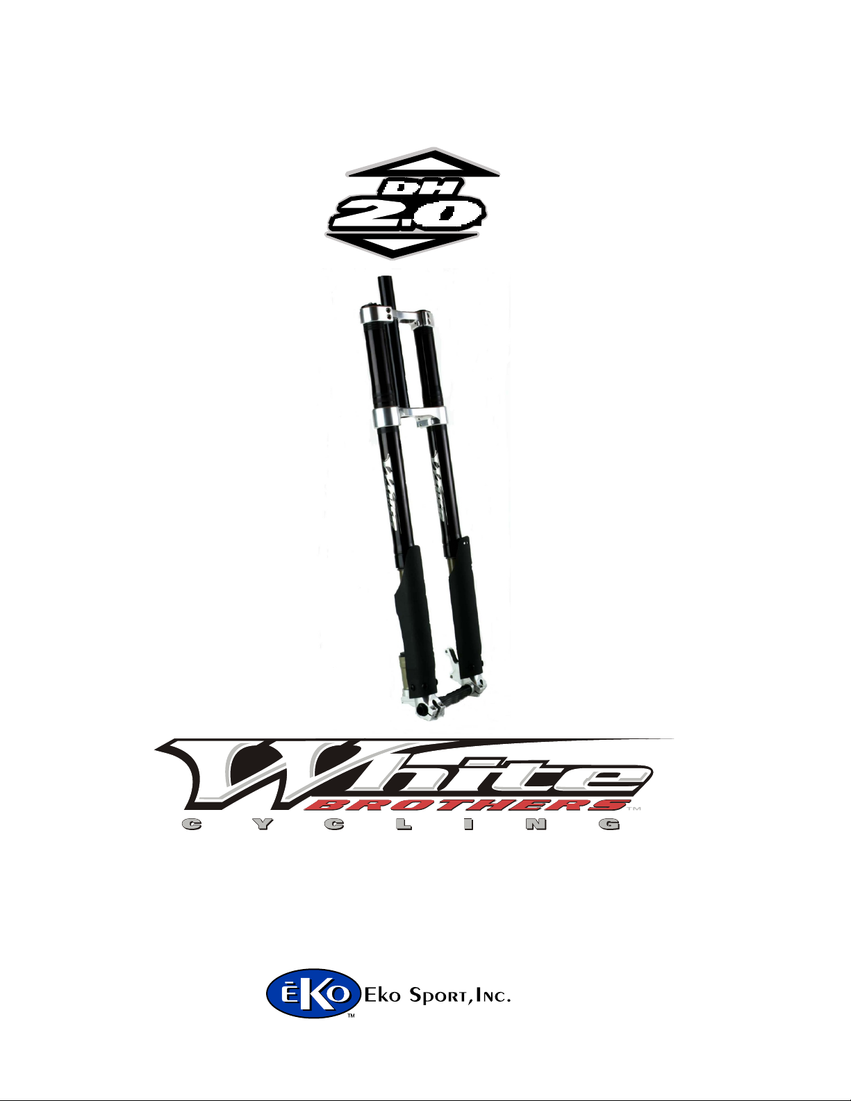
O W N E R S M A N U A L F O R
580 N. Westgate Dr.
Grand Junction, CO 81505 USA
1.800.999.8277
www.whitebrotherscycling.com
A division of
PAGE 1
Page 2

TABLE OF CONTENTS
SAFETY.......................................................PAGE 2
INTRODUCTION........................................PAGE 2
FORK INSTALLATION..............................PAGE 3
TUNING.......................................................PAGE 4
MAINTENANCE.....................................PAGE 5,6
EXPLODED VIEWS...................................PAGE 7
WARRANTY................................................PAGE 8
IMPORTANT
CONSUMER SAFETY INFORMATION
WARNING: RIDING A BIKE IS DANGEROUS. NOT PROPERLY MAINTAINING OR INSPECTING YOUR BIKE AND
IT’S COMPONENTS IS EVEN MORE DANGEROUS. IT IS ALSO DANGEROUS TO NOT READ AND FOLLOW
THESE INSTRUCTIONS.
1. NEVER REMOVE STEERER TUBE FROM CROWN. THIS IS A PRESSED IN PART. REMOVING IT WILL
RENDER BOTH THE CROWN AND STEERER TUBE INOPERABLE.* MAKE SURE THE FORK CAPS AND ALL
FORK HARDWARE (pinch bolts, etc.) ARE TIGHT BEFORE EACH RIDE.
2. DO NOT PERFORM ANY MODIFICATIONS OR ADJUSTMENTS THAT ARE NOT OUTLINED IN THIS
MANUAL. SEE THE TUNING SECTION FOR MORE DETAILS.
3. INSPECT YOUR FORK BEFORE EVERY RIDE. INSPECT THE CROWN, TUBES, AND AXLE SEAT AREAS FOR
ANY SIGNS OF FATIGUE, BENDING, CRACKING OR OTHER DAMAGE. IF YOU NOTICE ANY TYPE OF
DAMAGE, DO NOT RIDE IT. RETURN IT TO YOUR DEALER OR TO WHITE BROTHERS FOR A COMPLETE
INSPECTION AND NECESSARY REPAIR.
4. PERFORM ALL RECOMMENDED MAINTENANCE ACCORDING TO THE MAINTENANCE SECTION OF THIS
MANUAL. FAILURE TO PERFORM MAINTENANCE COULD DRASTICALLY REDUCE THE FORK’S LIFE,
PERFORMANCE AND CAUSE YOUR FORK TO BE A SAFETY HAZARD.
5. WHITE BROTHERS RECOMMENDS THAT YOU WEAR PROPER SAFETY EQUIPMENT EVERY TIME YOU
RIDE, INCLUDING AN APPROVED BICYCLE HELMET. NEVER RIDE AT NIGHT WITHOUT LIGHTS.
6. ALWAYS USE GENUINE WHITE BROTHERS PARTS. USE OF AFTERMARKET REPLACEMENT PARTS AND
UPGRADES VOIDS THE WARRANTY AND COULD CAUSE STRUCTURAL FAILURE.
7.WHITE BROTHERS FORKS ARE DESIGNED FOR OFF ROAD USE ONLY. THEY ARE NOT EQUIPPED WITH
REFLECTORS FOR ROAD USE. IF YOU ARE GOING TO USE YOUR FORK ON THE ROAD, HAVE A DEALER
OR MECHANIC INSTALL REFLECTORS THAT MEET THE CONSUMER PRODUCT SAFETY COMMISSION’S
REQUIREMENTS.
*IF SERVICE BECOMES NECESSARY OR REMOVAL OCCURS, PLEASE CALL WHITE BROTHERS CUSTOMER SERVICE FOR PRODUCT
EVALUATION AND DIAGNOSIS.
INTRODUCTION
Thank you for purchasing your new White Brothers fork. Our forks are designed to help you perform at your absolute peak.
Your new White Brothers fork has oil damping and is air and coil sprung for light weight performance. The springs and
damper is set stock to satisfy a wide range of rider weights and riding styles. Fine tuning can be easily accomplished by
changing air pressure and external damper settings. See the tuning section for details. For very heavy or very light riders,
replacement springs are available. Steering accuracy is improved over conventional MTB forks by utilizing superior materials
and design. Every effort has been made to make White Brothers forks very light and perform at a level superior to other forks
on the market. To ensure peak performance, proper installation and periodic maintenance is required. When riding on public
land, please respect the rights of others and stay on established paths and trails. By riding responsibly, you are helping ensure
the future of our sport.
PAGE 2
Page 3
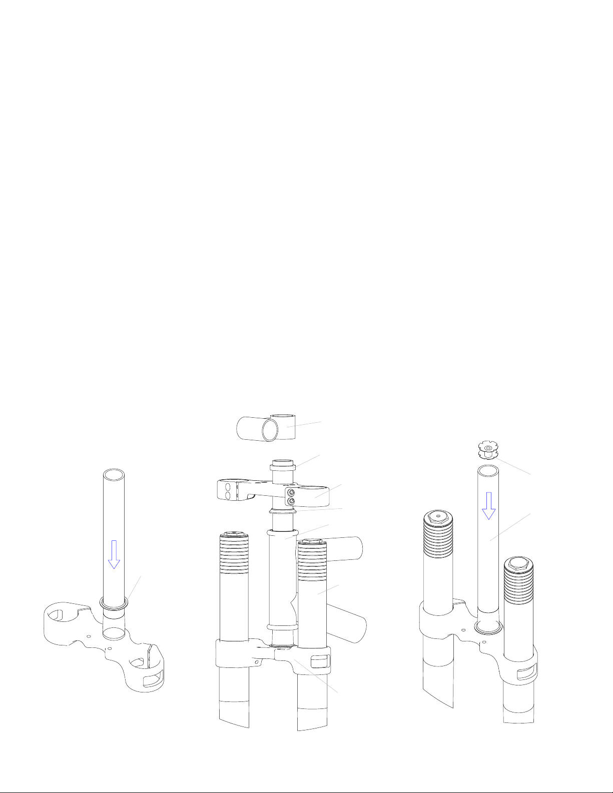
FORK INSTALLATION
White Brothers forks feature a 1-1/8” threadless steerer tube. If you have a threaded type fork on your bicycle, consult
your dealer for the appropriate upgrade parts necessary to convert to a 1-1/8” threadless steerer tube. Check with your
frame manufacturer to ensure your bike is designed for a triple clamp fork. If not, you may void your warranty.
1. Remove your old fork from the bicycle. Measure the diameter and length of your old forks steerer tube to ensure
that the White Brothers steerer tube is the correct diameter and sufficient length for the installation.
2. Remove the crown race from your old fork.
3. Press the crown race onto your new White Brothers fork.(see Figure #1)
4. Preassemble the headset by sliding the fork steerer tube through the bearings. Then install the head sets upper race,
upper triple clamp, headset spacer (optional), and stem onto the fork steerer tube. Adjust with optional spacers to
your preferred height. (See Figure #2) WARNING: Refer to the head set owners manual if there are any questions
about the head set installation.
5. Mark the steerer tube at the top of the stem. The steerer tube will now need to be cut to the correct length.
Disassemble and cut 3mm (1/8”) below the mark. Consult your dealer or mechanic if you don’t have the proper
tools to cut the steerer tube.
6. The star fangled nut must now be installed into the steerer tube. If you don’t have the set tool we recommend
dealer installation of this part. (See Figure #3)
7. Clean and grease all headset bearings and races to prepare them for assembly. Note: Replace the bearings if there is
any sign of wear or corrosion.
8. Now loosely assemble the headset, stem and handle bars as done in step four. (See Figure #2)
9. Install the headset top cap into the star fangled nut. Tighten until there is no play in the steering. The fork should
rotate freely in the head tube. Straighten the stem in relation to the front tire and tighten the pinch bolts on the stem.
Tighten the pinch bolts on the upper clamp and double check that the lower clamp bolts are tight. These can easily
be over tightened. We recommend tightening to 8 foot pounds. If there are any questions consult your dealer or
mechanic.
Head Set Race
Steering Stem
Optional Headset Spacer
Upper Triple Clamp
Headset Upper Race
Frame with
Headset Cups
Outer Fork Tube
Lower Triple Clamp
Star Fangled Nut
Steerer Tube
Figure #1
Figure #2
Figure #3
PAGE 3
Page 4

10. Slide the wheel in and line up the brake rotor with the brake caliper then line up the hub with the axle feet. Slide the 20mm
axle through the right side foot, hub and into the left side foot. Tighten the pinch clamps after the axle is properly seated and
tight.
11. Adjust your front brake according to the manufacture’s instructions.
12. Check to see that the brakes are adjusted and properly working. Make sure the brake line doesn’t interfere with any part of
the bike when the fork is compressed and released.
Warning: When installing the wheel or a new tire, check for minimum clearance. Measure from the highest point on the
tire to the under side of the crown. There must be 1/8” or 3mm more clearance than the fork’s travel to ensure adequate
clearance in all riding conditions. Any less clearance can cause the tire to hit the crown resulting in serious injury or death.
The DH 2.0 will not work on frames with head tubes longer than 5-1/2”.
TUNING
To get the most from your White Brothers fork, it is important
that you tune the forks to fit your style of riding and the conditions you ride in.
INITIAL BREAK-IN PERIOD
Your new fork is designed to break-in over a period of 10 hours or more of riding. As all the parts bed into each other, the
stiction (friction) of the fork will diminish and the fork will absorb the bumps better. After this initial break-in, fine tuning the
air spring and hydraulic damper may be beneficial to achieve the best possible fork performance for your weight and riding style.
TUNING YOUR SPRINGS
1. There are two ways to adjust your forks spring action. The first is by changing the air pressure and the second is changing the
springs for a completely different rate. Your White Brothers fork comes equipped with a medium rate spring adjusted with
zero air pressure for minimum pre-load.
2.
Though the medium rate springs that are fitted in your White Brothers forks should satisfy most rider weights and conditions,
for very light or very heavy riders, a spring change may be necessary. If you are a lightweight rider and feel you are not
getting the full travel out of your fork, see “Disassembly of the Spring Leg”. Remove the o-ring (#20) on the double sided
spring guide (#14). This will increase the air volume size and decrease the ramping of the fork. For heavier weight riders that
feel they are constantly using too much fork travel, the optional heavy fork springs would be recommended. A good way to
test the travel you are using with your fork is to tie a zip tie around fork stanchion and slide it up to the bottom of the forks
wiper seal. Go and ride a variety of conditions you normally experience, including some conditions that you feel should use
the full fork travel. After the ride, inspect the position of the zip tie. Measure that position from the fork wiper seal to the axle
clamp. Next remove the fork cap and compress the fork to full bottom out. If the zip tie moves more than 1/4”, your spring is
probably too stiff and a change to a softer spring may improve your ride. Very heavy riders may note that the zip tie slides
down the fork stanchion quite far even over minor bumps and this could indicate the need for a heavy spring rate.
Pre-load is changed by adding or removing air from spring leg. More air pressure will have less sag and a firmer feel. Less air
3.
pressure will have more sag and a softer feel. The fork is designed to use zero pressure and should never exceed 40 lbs.
4. If after adjusting as outlined in steps 1-3 you feel the fork is too soft or too firm, you may need to change the spring out.
Contact White Brothers for a replacement spring. See the “Disassembly of the Spring Leg” and “Reinstalling the Springs and
Left Hand Top Cap” sections to replace the spring.
TUNING YOUR DAMPER
1. Rebound damping is adjusted by turning the slotted brass adjuster on the top cap of the right leg. The adjuster has 8 turns of
adjustment. Turn the adjuster clockwise for slower rebound. To speed up rebound, turn the adjuster counter-clockwise. Start
with a middle setting and fine tune the rebound from there. Proper rebound will allow the tire to track the ground over
consecutive bumps. Rebound that is set too slow will pack-up (feel harsh over consecutive bumps) while rebound set too fast
will cause the fork to top out harshly. If the fork is topping out and you have the correct spring for your weight, turn the
adjuster one turn at a time until the top-out stops.
2. Compression damping can be changed two ways: (1) by adjusting the compression damping screw on the back of the
canister on the bottom of the right fork leg. Threading it in slows compression and threading it out speeds up compression;
and (2) by adding or removing air pressure (or nitrogen)from the canister at the bottom of the right leg. Pop of the dust cap
and adjust between 50 psi min. and 150 psi. max. Adding air will increase the compression damping (slow it down) and
removing air will decrease compression damping (faster compression). Less compression damping will increase the fork dive
but will feel smoother over small bumps. More compression damping will feel stiff over small bumps but will be more
resistant to bottoming.
PAGE 4
Page 5

MAINTENANCE
Your White Brothers fork requires periodic maintenance to ensure peak performance and long life. Neglecting proper
maintenance will reduce the fork’s life. Internal build up of water and dirt or a lack of lubrication will cause excessive wear
and void the warranty.
BEFORE EVERY RIDE: Visually inspect your fork for bent or broken parts, loss of oil, abnormal sounds or other
indications of possible fork failure. Compress you fork to verify proper function. Check all other bicycle components to
ensure proper working order.
AFTER EVERY RIDE: Clean and dry the exterior of your fork. When cleaning the fork, do not direct the water spray at the
seals. Visually inspect your fork for damage.
*EVERY 30 HOURS OF RIDING: Your fork should be disassembled, inspect, cleaned and re-grease. If the fork appears to
be relatively clean, you can go 40 hours between servicing. If the fork appears excessively dirty you should service it every
20 hours. The three things that will effect the service interval and performance of your fork are water, mud and dust. How
much you use your fork in those conditions will determine how much service it requires.
*EVERY 100 HOURS OF RIDING: Complete service should include removing the upper fork legs cleaning and re-
greasing all shafts, bushings and seals. Check damper leg for proper function(see Disassembly of the Damper Leg). NOTE:
Disassembly of the hydraulic damper should be left for the White Brothers factory. At this time, the fork should be
carefully inspected for wear and damage before reassembly. Contact White Brothers for replacement parts and service. We
recommend that this service be performed by a qualified dealer or the White Brothers factory.
*White Brothers recommends that you consult with a qualified technician before performing the following:
BASIC FORK DISASSEMBLY
Removal of the Leg Assemblies
1. Disconnect the front brake and loosen the pinch clamp bolts at the bottom of each leg. Un-thread the axle with a 17mm
wrench and remove the wheel.
2. Loosen the four M6 upper clamp bolts. Before loosening the lower clamp bolts, start to loosen the top caps using a 25mm
or 1” socket. Then loosen the lower clamp bolts and slide the legs out of the clamps.
Disassembly of the Spring Leg Assembly (Left Hand)
1. Unscrew the top cap from the outer leg. Check for noticeable play between the stanchion tube and the outer fork tube. If
there is play, contact White Brothers or a qualified dealer for service.
2.
Place the axle clamp into a vise with soft jaws or some type of protection that will not harm the finish. Lower the outer leg
until the seal touches the axle clamp.
3.
Use a 9mm wrench to loosen the rod from the air cap.. Hold the shaft and unscrew the air cap counterclockwise from the
shaft.
Remove the leg from the vise and remove the inner leg from the outer leg. Return the leg to the vise and remove the
4.
stanchion plug using a 25mm wrench.
Remove the fork guard from the dropout. There is a set screw positioned between two of the fork guard screw holes that
5.
should be removed at this time. Use compressed air to remove the springs by directing air into the hole to push the springs
and spring separator seal out the top of the leg.
Clean and inspect all the parts. Check the DU bushings inside the outer leg carefully for wear. This is done by looking at
6.
the color of the clean bushings. If the bushings are dark gray, they are in good condition. If they are bronze/gold in areas,
they are worn and can cause fork stanchion damage. Please note that special tools are required to remove and replace these
bushings. This service can be performed directly through White Brothers or a qualified dealer.
Next, inspect the fork stanchion tubes for wear, nicks or scrapes. These will cause premature wear on the seals and DU
7.
bushings. If there is any damage to the stanchion tubes, have them replaced.
8. Inspect the o-rings for damage. There is a o-ring on each end of the control rod and on both spring guides. If there’s any
question about them sealing, replace the o-rings.
Disassembly of the Damper Leg Assembly (Right Hand)
NOTE: 10mm Clamp Blocks are required to work on the damper side leg. Contact White Brothers for the proper tools.
1. Unscrew the top cap from the outer leg. Check for noticeable play between the stanchion tube and the outer fork tube. If
there is play, contact White Brothers or a qualified dealer for service. Slide the outer leg down to the axle clamp.
2. Carefully clamp the shaft in the vise using 10mm clamp blocks. Note: You can easily damage the shaft by scratching or
bending it. When clamping, be sure the fork isn’t touching the bench under the vise.
3. Unscrew the top cap counterclockwise from the shaft. Note there is a small spacer under the cap that can fall out.
4. Remove from the vise and pull the inner leg out of the outer leg.
PAGE 5
Page 6

BASIC FORK REASSEMBLY
Rebuilding the Outer Legs
1. Throughly clean all the parts in a mild solvent.
2. Check the condition of the wiper seals and the inner oil seal for cracks, abrasions or obvious signs of wear. Note: If
the wiper seals are in question, replacement is always recommended. It helps to keep the dirt out, especially when
riding in harsh conditions.
3. The wiper seals can be removed with a spoon style tire iron or something similar and can be re-installed using a
large socket as a driver to install squarely in to the leg. Note: Jamming the seals in at an angle can crush the steel
casing and the seal will no longer seal correctly and/or stay in place.
4. Apply grease to the DU bushings down inside the leg. Verify the bushings are in good working order. Bushings are
replaceable but require a number of special tools to remove and install. Return to White Brothers to have the
bushings changed if required.
Rebuilding the Spring Leg Subassembly
1. Throughly clean all the parts in a mild solvent.
2. Check the condition of the o-rings and replace if necessary.
3. Install the parts as shown in the exploded view, using heavy grease on all internal parts.. Thread the assembly into
the inner leg. Use a socket to get the stanchion plug started, being carful not to cross thread it into the stanchion.
4. Install the 6mm set screw in the dropout that was removed in step 5 of ”Basic Fork Disassembly”.
Rebuilding the Damper Leg Assembly
1. Throughly clean all the parts in a mild solvent.
2. Inspect for obvious signs of damage. Check the air pressure. Test the damper by pushing the shaft down. It should
compress and extend just over 8” in a controlled manner. Do not pull the damper rod out more that 8 1/2” as it
may cause air to enter the damper. Screw the compression adjuster in to insure the damper slows when adjusted.
At the top of the stroke, check for dead spots in the damping and if the damper shaft does not return to full extension,
this indicates the need for damper service. Contact White Brothers for service.
Reinstalling the Outer Legs
1. Apply Slick Honey or other non-lithium based suspension lube to the DU bushings inside the outer leg. Make sure to
lube the lower DU bushing which is deep in the outer leg.
2. With all parts cleaned and reinstalled with new grease, fit the outer leg over the stanchion tube and gently rock and
slide the legs until the inner leg slides into the bushings. Slide the outer leg all the way down to the axle clamp. Check
for noticeable play between the stanchion tubes and the fork lower. If there is play, contact White Brothers for service.
Reinstalling the Springs and LH Top Cap
A 9mm wrench will hold the flats on the shaft as you thread the top cap down until it stops. Hold the top cap with a
1.
15/16” socket and tighten. Be careful to not damage the o-ring seal.
Thread the top cap into the outer leg and tighten. Note: A little more than hand tight is all that is necessary, as the
2.
upper clamp will hold the top caps tight.
Reinstalling the RH Top Cap
1. Screw the rebound needle in clockwise until it stops then back it out 3 to 4 turns.
2. Install the small spacer under the top cap if you removed it earlier.
3. On the damper shaft, install the chrome bottom out spring onto the seal head, spring spacer and then the yellow
bumper with heavy grease on all parts. The parts will be seated the first time the fork bottoms out.
4.
Carefully clamp the shaft in the 10mm clamp blocks. Note: You can easily damage the shaft by scratching or bending
it. When clamping, be sure the fork isn’t touching the bench under the vise.
Install the top cap onto the damper shaft and tighten. Remove the assembly from the vise and thread the top cap into
5.
the outer leg and tighten. Note: A little more than hand tight is all that is necessary, as the upper clamp will hold the top
caps tight.
Readjust the rebound needle to your preferred position.
6.
PAGE 6
Page 7

25
26
22
24
12
55
Exploded Views
The following is an illustration and parts table
which gives you the exploded view of your White
Brothers fork. The parts table indicates the part
numbers for each individual part in the fork.
Reference these numbers when ordering
replacement parts. See your local dealer or contact
White Brothers to order the parts you require.
56
55
3
10
16
61
19
18
62
15
62
17
20
4
14
20
13
60
27
66
28
63
50
21
11
55
2
50
21
49
48
39
46
47
45
54
66
6
5
65
64
44
44
44
43
42
41
38
67
?
8
54
1
59
59
59
58
57
9
1
23
46
29
59
59
59
58
57
9
51
33
7
31
34
30
32
35
36
37
53
52
53
?
67
PAGE 7
Page 8

ITEM NO. QTY. PART NO. DESCRIPTION
1 2 100021-100022 DH Outer Leg
2 1 P1159-1 Crown Assm.
3 1 P1157-1 Upper Crown
4 1 100046 Main Spring
5 1 100609 Spring Leg Assm.
6 1 100610 Damper Leg Assm.
7 1 97-3677 Axle
8 1 97-3677-1 Axle Spacer
9 2 97-1351 Wiper Seal
10 1 100611 Stanchion Plug
11 1 100600 DH Air Cap
12 1 P2348 DH Damping Cap
13 1 97-3500 Bottom Out Spring
14 1 100612 Spring Seperator Seal
15 1 100613 Control Rod
16 1 100043 Negative Spring VT
17 1 100614 Control Rod End
18 1 97-3342 Bumper Soft
19 1 P3321 Rebound Bumper Spacer
20 2 100262 O-Ring 211
21 2 100054 Schreader Valve Assembly
22 1 P3220 Spring Progression
23 1 100615 Seal Head
24 1 100616 Top Cap Plug
25 1 P3290 Compression Bumper Medium
26 1 97-3914 Spring Spacer 5mm
27 1 P2028 DH Damper Shaft
28 1 P2035 Needle Assm.
29 1 97-1409 Shaft Seal
30 1 P2014 Check Valve Guide
31 1 P2015 Check Valve Spring
32 1 P2004 Check Valve 22x12x0.02
33 1 P2012 Piston
34 1 P3000 Piston Band
35 1 P2006 Low Spd Shim 22x8x0.02
36 1 P2005 Belvil Washer
37 1 P4010 Shim Stack Bolt
38 1 P3026 O-Ring 024
39 1 P1515-1 Reservoir Can
40 1 P2001B Shim
41 1 29-136 Shim
42 1 P2016 Compression Piston
43 1 P3028 O-Ring 021
44 3 29-127 Shim
45 1 P4011 Piston Bolt
46 2 P3021 O-Ring 118
47 1 P2010 Floating Piston Assm.
48 1 100162 O-Ring 2x22.5
49 1 100627 Air Cap Triple Clamp Series
50 2 P4650 Dust Cap
51 1 98-406-1 LH Stone Guard
52 1 98-406-2 RH Stone Guard
53 6 P4005 Screw Nylon Guard
54 3 97-9200 M5x16mm Screw
55 11 97-852 Bolt M6
56 1 97-9300 Star Nut
57 2 P4301 C Clip
58 2 P3060 Oil Seal
59 8 97-986 DU Bushing
60 1 100617 Spacer
61 1 100618 Topout Stop
62 2 100033 O-Ring 010
63 1 P2025-1 Shaft Stop
64 1 P4015 Retaining Pin
65 1 P4004 Compression Adjuster Screw
66 2 97-1418 O-Ring 006
67 2 P4051 Set Screw 6mm x 6
PAGE 8
Page 9

Owners Name:___________________________________________________________________________
Address:________________________________________________________________________________
_______________________________________________________________________________________
Phone:_________________________________________________________________________________
Purchase Date:___________________________________________________________________________
Purchase Location:________________________________________________________________________
Serial #: Located on lower back side of right axle clamp.__________________________________________
MAINTENANCE LOG
Date Service Performed Date Service Performed .
WARRANTY CLAIMS
White Brothers forks are designed to enhance riding pleasure and as such are warranted to be free from defects in materials and
workmanship for a period of one year from the date of purchase. On receipt if it is found to be defective, White Brothers will
determine replacement or repair of the fork. This warranty is the sole and exclusive remedy. White Brothers shall not be liable for
any indirect, special or consequential damages. Warranty does not apply to any product that has been installed improperly or
adjusted using methods not outlined in this manual. Warranty also does not cover forks that have been misused, or forks that have
altered/missing serial numbers (located on the back of the right fork stanchion). The fork is not warrantied against damage in the
appearance of the fork or for modifications not outlined in this manual. This warranty does not cover breakage, bending, or
damage that may result from crashes, falls or abuse. Normal wear (i.e. seals, bushings, sliders finish, etc) and wear and damage
caused by lack of proper maintenance is not included. *The warranty registration card must be filled out and returned within
30 days of purchase to activate and validate this warranty. A copy of the proof of purchase must be included with all
warranties. Customers in the US please contact White Brothers or your dealer for a Return Authorization Number (RA#) before
returning the forks. All forks returned for inspection must be sent freight paid to:
580 N. Westgate Dr.
Grand Junction, CO 81505 USA
1.800.999.8277
www.whitebrotherscycling.com
A division of
*Consumers outside the US please contact the dealer or distributor in your area.
PAGE 9
 Loading...