

Page 1
© Copyright 2006-2007 White Box Robotics Inc. and Frontline Robotics Inc
Page 2

Disclaimer
Working with electronics and installing the plastics will require care and patience. PROPER
GROUNDING PROCEDURES before handling the electronics. Touching the robot chassis (which is
common grounded throughout) and at the same time touching something that is grounded in your
home/office like metal pipes or the kitchen tap.
It is also expected that, working in a small area inside the unit that you perform careful and safe
handling of the hardware so as not to cause short circuits. We ask that you make sure you give yourself
enough working area and time for installation so as not to damage either the plastics or the electronics.
Liability
In no event will White Box Robotics, Inc. or Frontline Robotics, Inc. be liable for any damage,
including loss of data or profits, cost of cover, or other incidental, consequential or indirect damages
arising from the installation maintenance, use, performance, failure or interruption of White Box
Robotics, Inc. or Frontline Robotics Inc. products, whatever the cause and on any theory of liability.
This limitation applies even if White Box Robotics, Inc. or Frontline Robotics Inc. has been advised of
the possibility of such damage.
© Copyright 2006-2007 White Box Robotics Inc. and Frontline Robotics Inc
Page 3
Unpacking the Robot
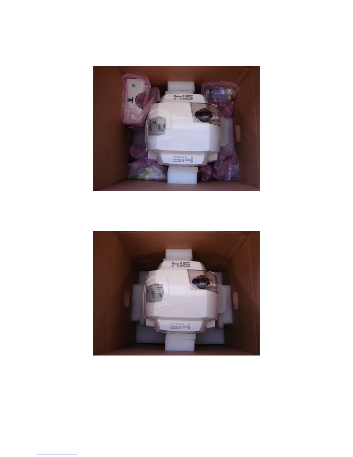
The following image shows how the PC-BOT should have arrived in the shipping box.
STEP 1 – Un-packing the robot
Remove the peripheral equipment wrapped in bubble wrap.
© Copyright 2006-2007 White Box Robotics Inc. and Frontline Robotics Inc
Page 4
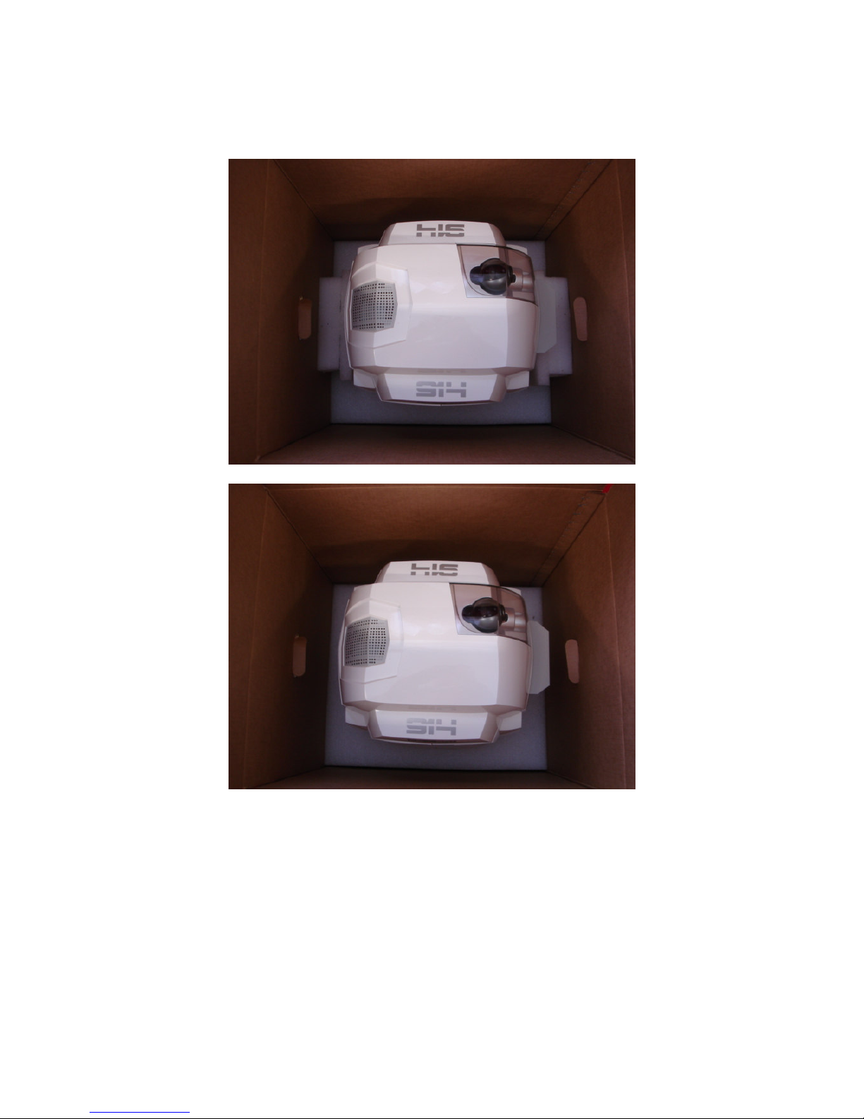
STEP 2 – Un-packing the robot cont.
Carefully remove the side and front/back supporting foam.
© Copyright 2006-2007 White Box Robotics Inc. and Frontline Robotics Inc
Page 5
STEP 3 - Un-packing the robot cont.
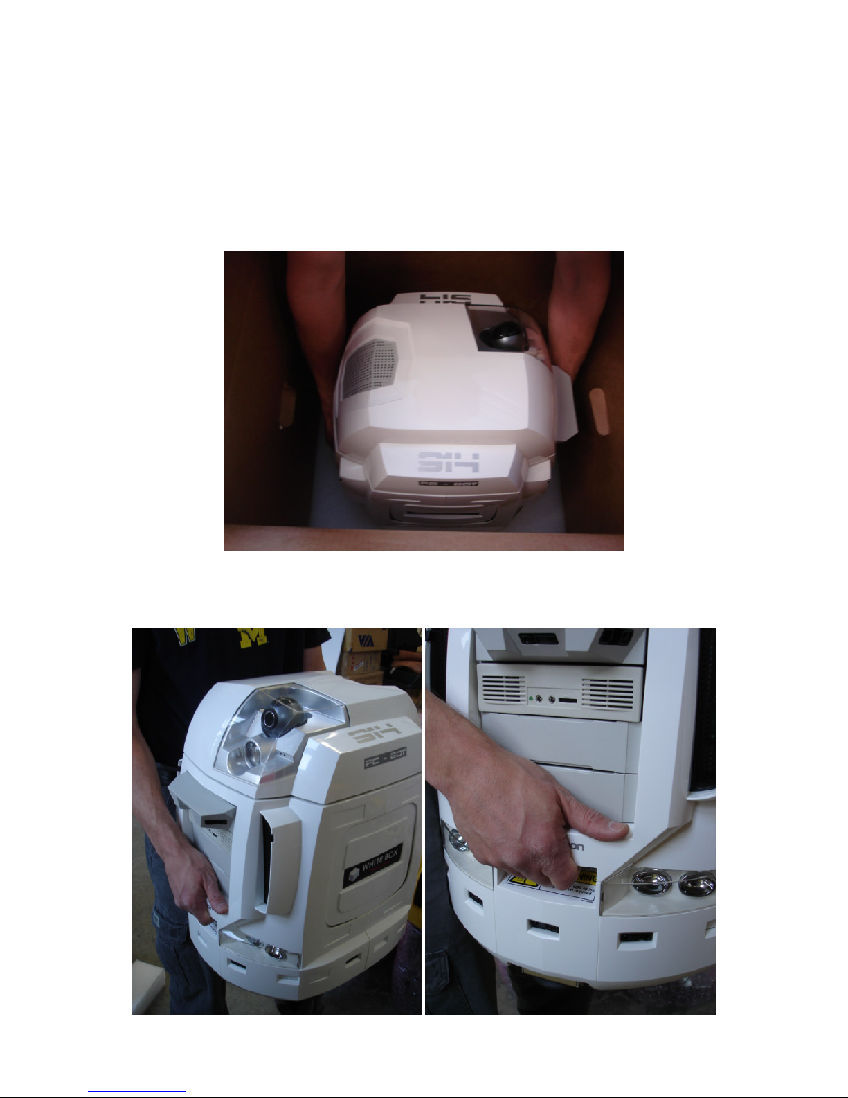
Reach into the box and grab the handles on the PC-BOT. They are somewhat hidden from above. Lift
the robot straight up and out of the box.
WARNING! This robot is heavy. People with back problems should not attempt to lift this robot.
Always use proper lifting technique when lifting heavy items. Keep you knees bent and your back
straight and lift gently.
The following image shows where the handles are located, you’ll have to feel for them when the robot
is in the box. There are two handles front and back.
© Copyright 2006-2007 White Box Robotics Inc. and Frontline Robotics Inc
Page 6
Setting-up the robot
STEP 1 – Charging the robot batteries
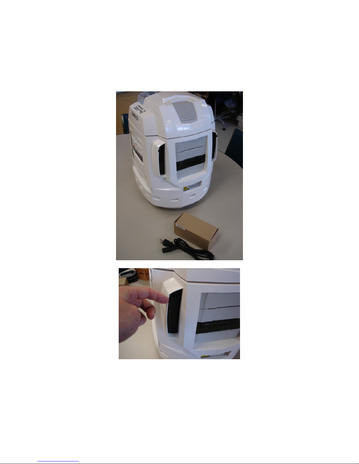
Now that the robot is out of the box, you should plug the charger in to charge the batteries. The charger
connector is found behind the left rear vent door on the back of the robot.
Flip the door open as shown in the above picture.
© Copyright 2006-2007 White Box Robotics Inc. and Frontline Robotics Inc
Page 7
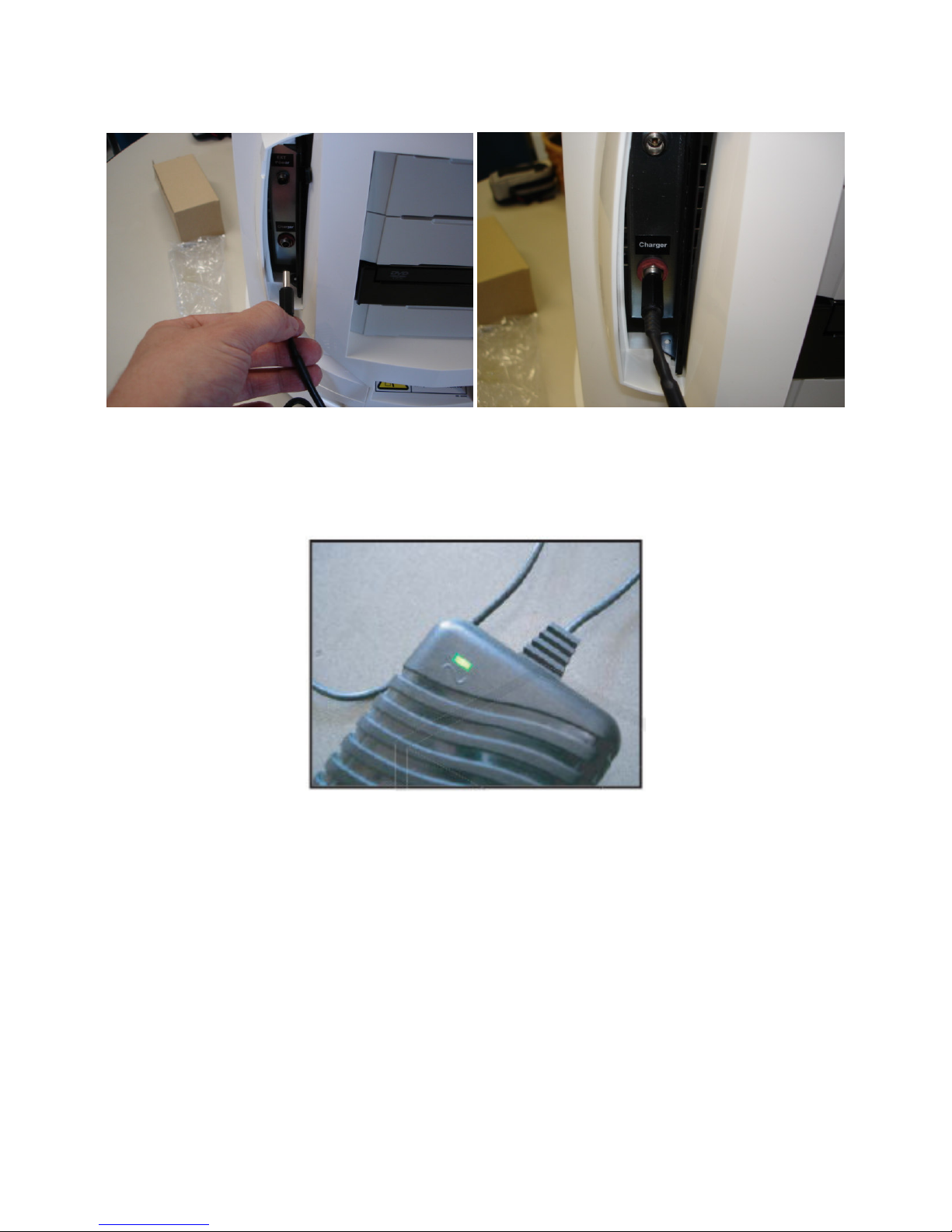
Unpack the charger and plug the charger jack into the lower connector on the robot labeled “Charger”.
The charger LED will first be GREEN after the AC cord is plugged into the wall. It will then change to
ORANGE when it is charging the batteries on the PC-BOT. It will then switch back to GREEN when
the batteries are fully charged (it typically takes 2 -2.5 hours to charge the batteries from the autoshutoff point).
Charging and shutdown
If the battery level goes below 11.2V the robot will auto-shutdown. Either while you are running the
robot, and especially when you are finished with it for the day, PLEASE REMEMBER TO RECHARGE THE BATTERIES.
© Copyright 2006-2007 White Box Robotics Inc. and Frontline Robotics Inc
Page 8
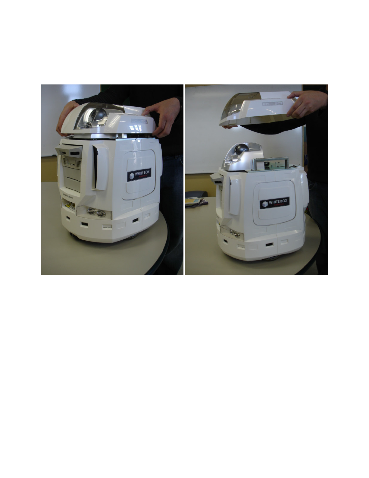
STEP 2 – Removing the head panel
The head and front/back torso body panels are attached with ball studs and sockets. This allows for
easy removal of the panels without tools. Gently remove the head by grabbing under the separation
(between the head and torso plastics) and pulling straight up.
© Copyright 2006-2007 White Box Robotics Inc. and Frontline Robotics Inc
Page 9
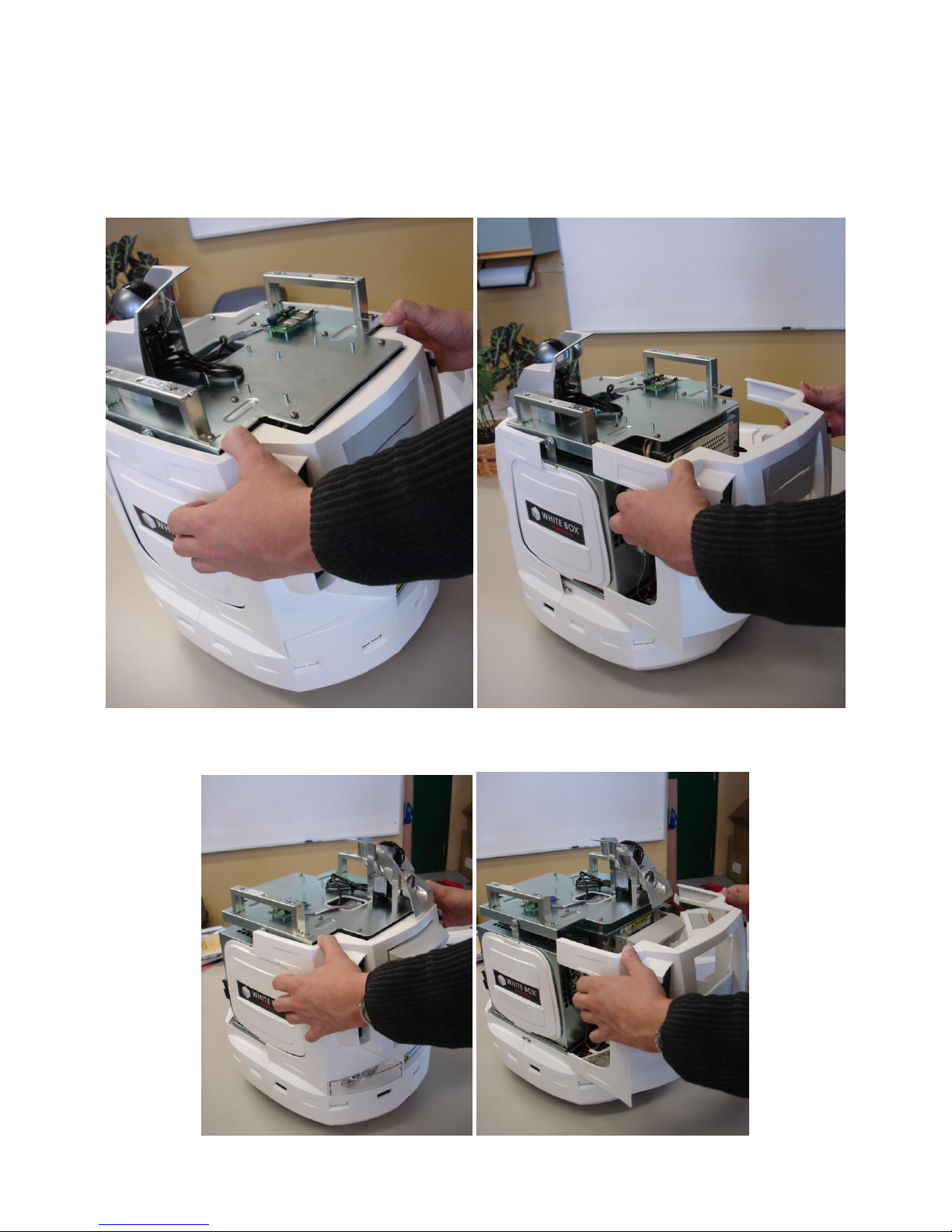
STEP 3 – Removing the body panels
The torso body panels are removed in the same way as shown, except pulled backwards or forwards
depending on the torso body panel. You can use your thumbs to leaver while pulling on the body
panels with your finger tips.
Both body panels are removed in the same way.
© Copyright 2006-2007 White Box Robotics Inc. and Frontline Robotics Inc
Page 10
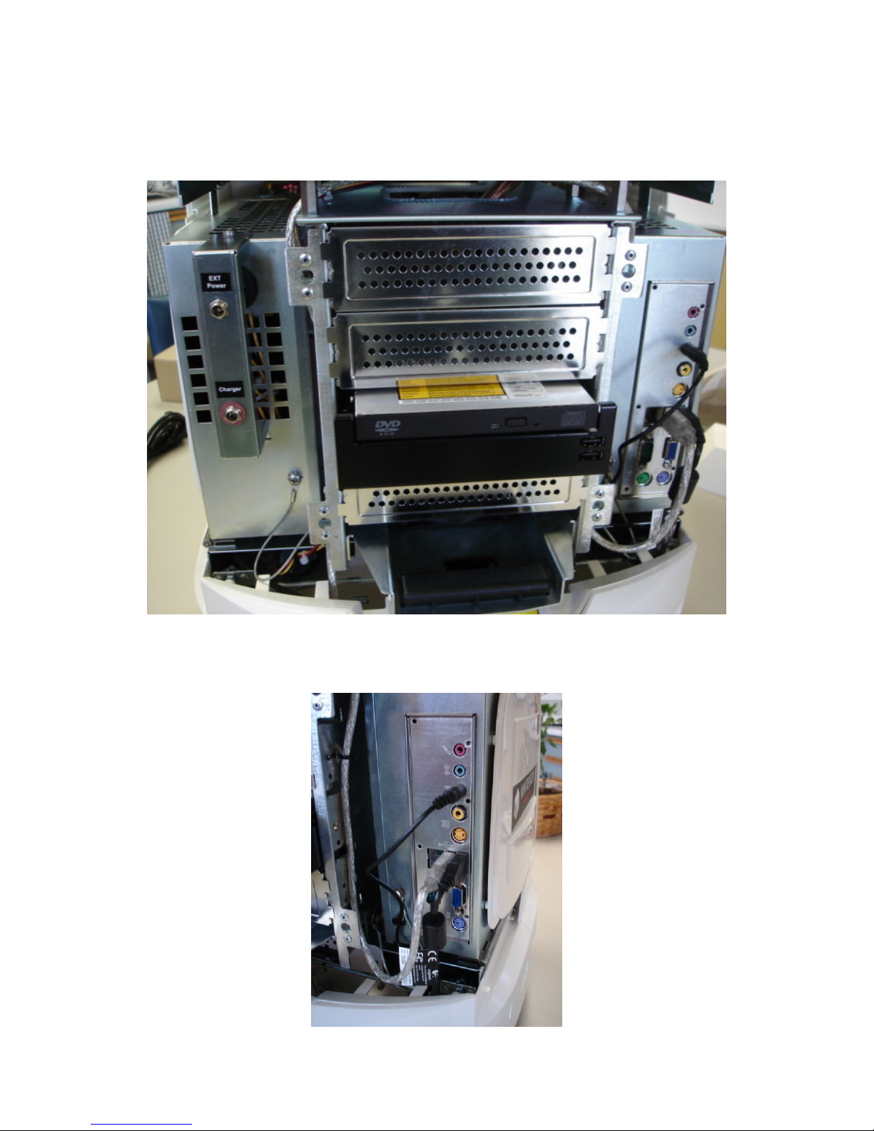
STEP 4 – Plug in the monitor, keyboard and mouse
When viewing the back of the robot, you will see the External Power Supply jack (power supply not
included) and Charger jack on the left side, and on the right side the back panel of the Mini-ITX.
Plug the monitor, keyboard and mouse into the Mini-ITX back panel in order to setup your robot, like
the network etc.
© Copyright 2006-2007 White Box Robotics Inc. and Frontline Robotics Inc
Page 11
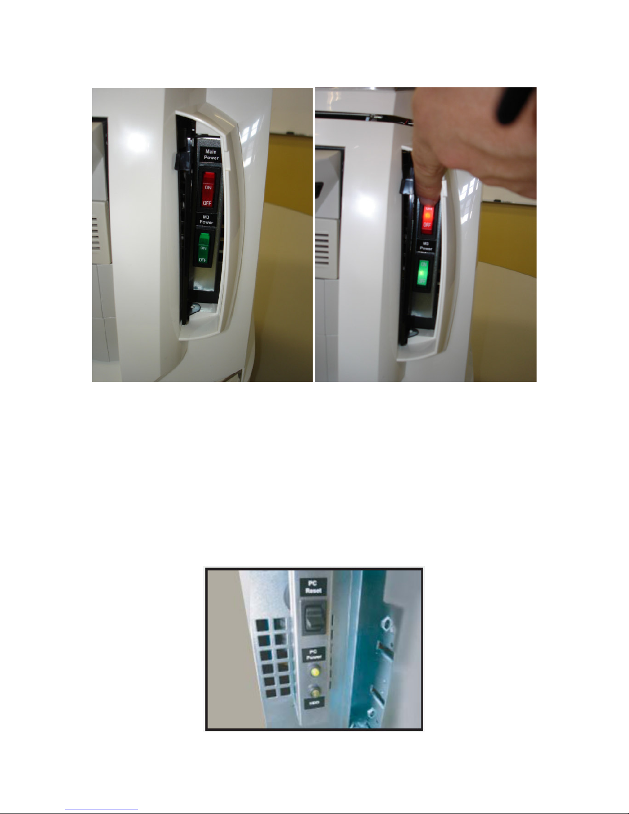
STEP 5 – Start your system
Switch on the Main Power switch (RED) AND M3 Power switch (GREEN) on the front of the robot.
WAIT 5 seconds and the M2-ATX Power Supply will cycle the power to the PC automatically.
The M3 Power switch is used to turn on the M3 Controller. If this switch is OFF, the M3 will not be
able to drive the motors or read the sensors.
When the battery voltage drops to 11.2V (i.e. when the batteries need recharging, the M2-ATX will
cycle the power to the PC again to auto-shutdown before the power is cut (45 seconds later) and the
batteries are protected from total discharge.
This is the same as the user pushing the PC ON switch on the CPU and shutting down the computer.
© Copyright 2006-2007 White Box Robotics Inc. and Frontline Robotics Inc
Page 12
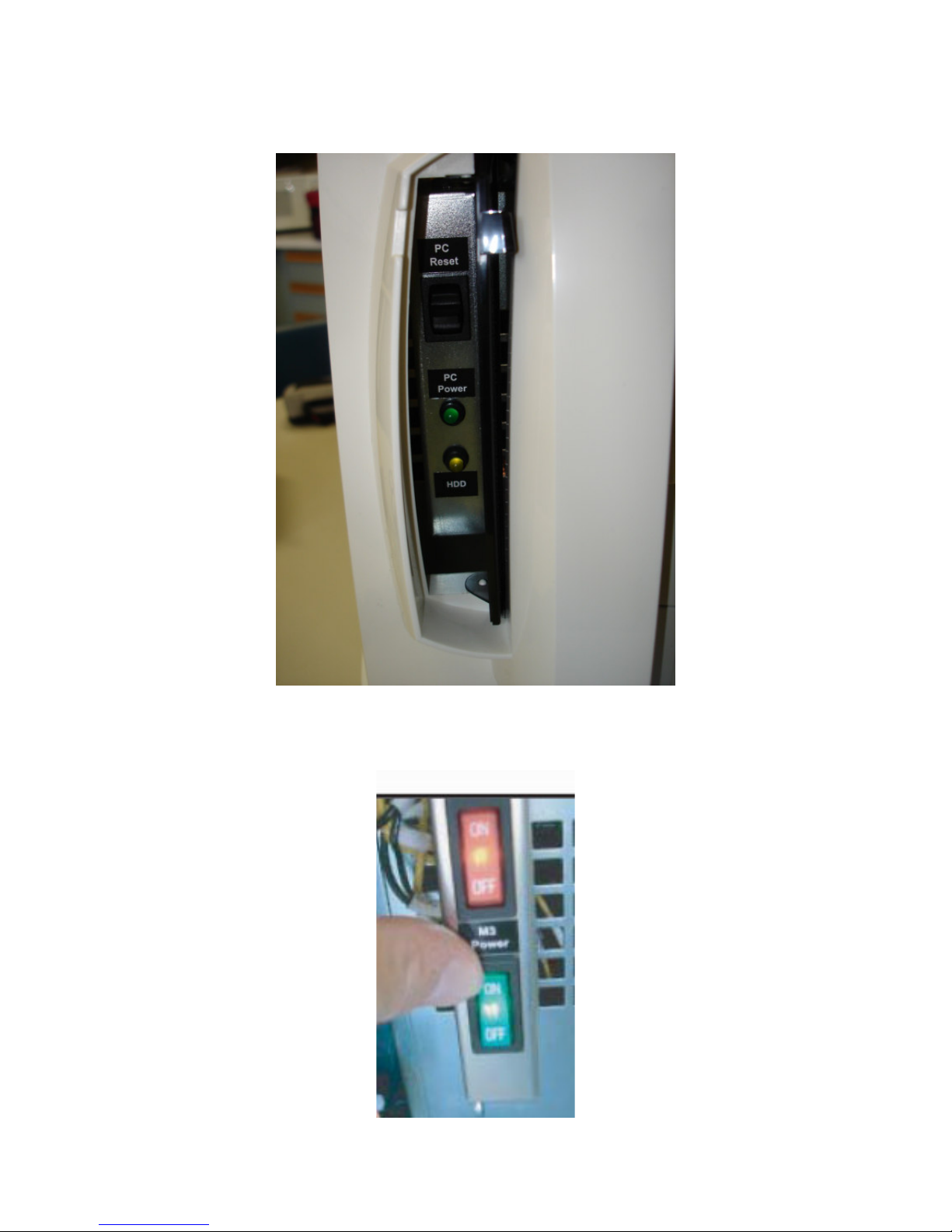
On the other side of the front of the robot, you can still use the PC ON and PC Reset switch just like on
a regular computer.
NOTE: If the robot is sitting on a desk, it might be advisable to turn the M3 Switch OFF so that
the robot cannot drive off the table.
© Copyright 2006-2007 White Box Robotics Inc. and Frontline Robotics Inc
Page 13
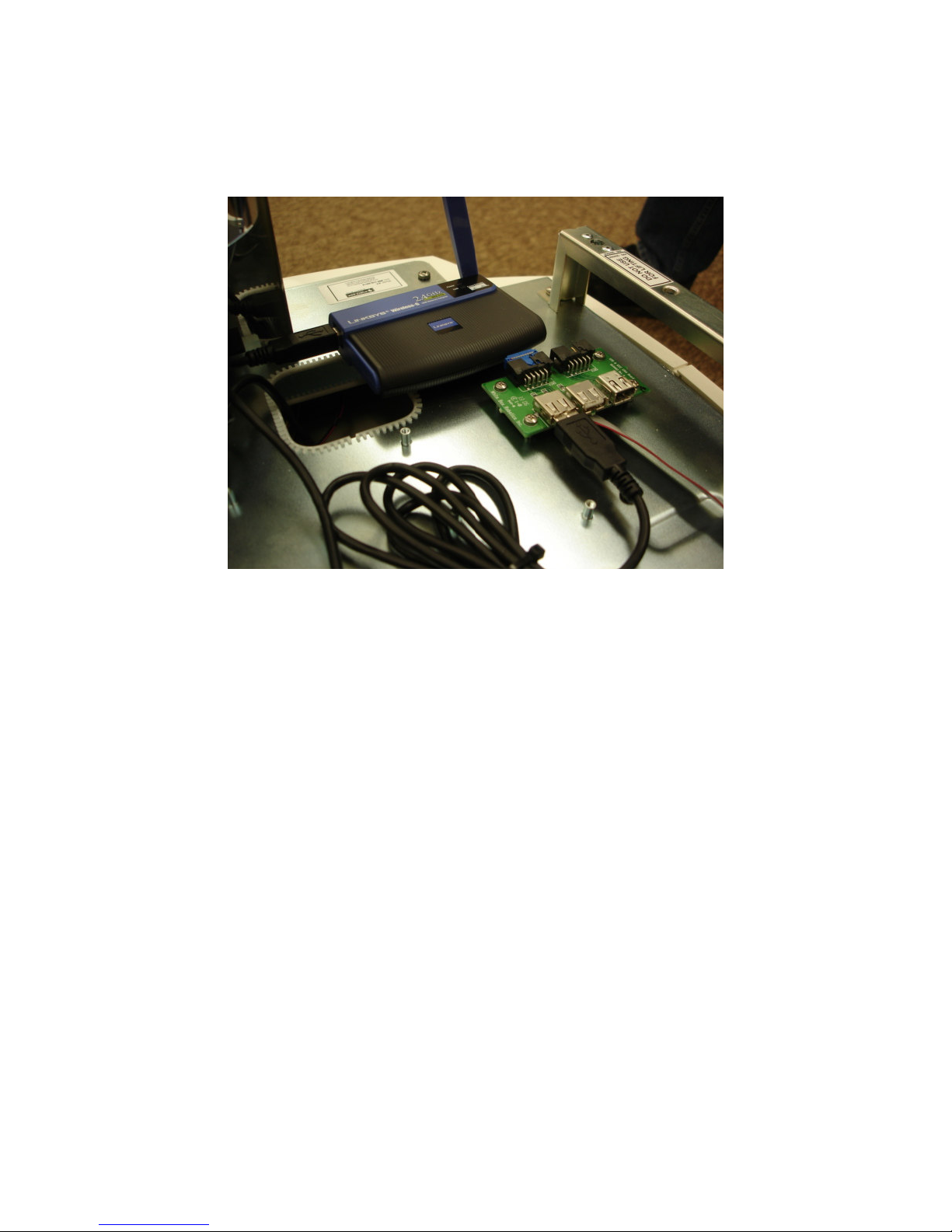
STEP 6 – Connecting Peripheral Devices
You should connect the Wireless device to the USB board mounted on the head if this is not already
done.
In this location the head can still be placed back on the robot and not interfere with the Wireless USB
Network Adapter or its antennae.
© Copyright 2006-2007 White Box Robotics Inc. and Frontline Robotics Inc
Page 14

Reference Documents and Links
White Box Robotics Webpage: http://www.whiteboxrobotics.com/
The Official Enthusiast Site for the 914 PC-BOT: http://www.914pcbots.com/community/
Support Documents – (Quick Start Guides, Basic Unit Computer Installation, Plastics Assembly, etc.)
http://www.whiteboxrobotics.com/2006/PCBOTs/support.html
Technical Specifications
Wiring and Power: http://www.whiteboxrobotics.com/2006/PCBOTs/pdf/PC-Bot_Tech_Spec-
WiringPowerv1.1.pdf
I/O Board Block Diagram: http://www.whiteboxrobotics.com/2006/PCBOTs/pdf/PC-
Bot_Tech_Spec-IOBoardBlockDiagramv1.1.pdf
Infra-red Sensors: http://www.whiteboxrobotics.com/2006/PCBOTs/pdf/PC-Bot_Tech_Spec-Infra-
redSensorsv1.1.pdf
© Copyright 2006-2007 White Box Robotics Inc. and Frontline Robotics Inc
Page 15
PC-BOT Software Section
Disclaimer:
This handbook is intended to introduce the basics of using Visual Studio Express as
development software for the White Box Robotics 914 PC-BOT and is not meant to
replace the actual Visual Studio manuals. You will still need to go through the tutorials
and read the documentation listed on the Microsoft Visual Studio Express webpage:
http://msdn.microsoft.com/vstudio/express/
Introduction
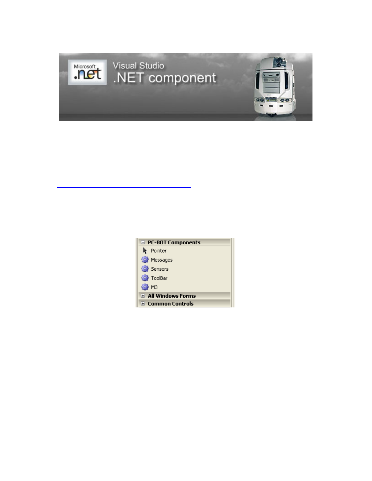
There are five PC-BOT components for Visual Studio 2005. Drive, Messages, Sensors, M3, and
ToolBar.
A Visual Studio Developer can drag and drop these components in to any Windows forms project. The
developer may write their code in any of the .NET supported languages (Visual Basic, C#, J#, C++)
© Copyright 2006-2007 White Box Robotics Inc. and Frontline Robotics Inc
Page 16
Step 1
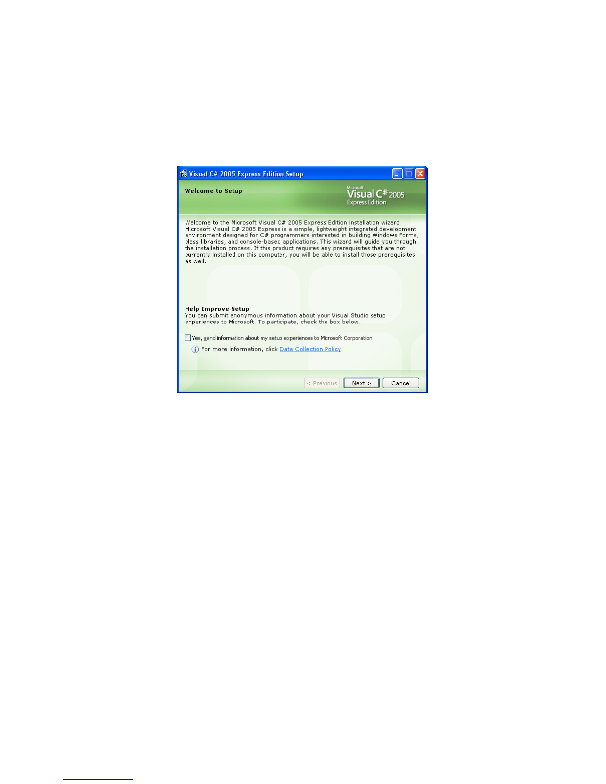
Download and install Visual Studio Express (its free) from the Microsoft website:
http://msdn.microsoft.com/vstudio/express/
Click the ‘Download’ button and choose the tool you wish to create your projects under. The sample
software was created under C# so this is what the guide will use.
Step 2
Download and install the ‘Additional components’ listed further down the webpage for the tool you
selected.
© Copyright 2006-2007 White Box Robotics Inc. and Frontline Robotics Inc
Page 17
Step 3
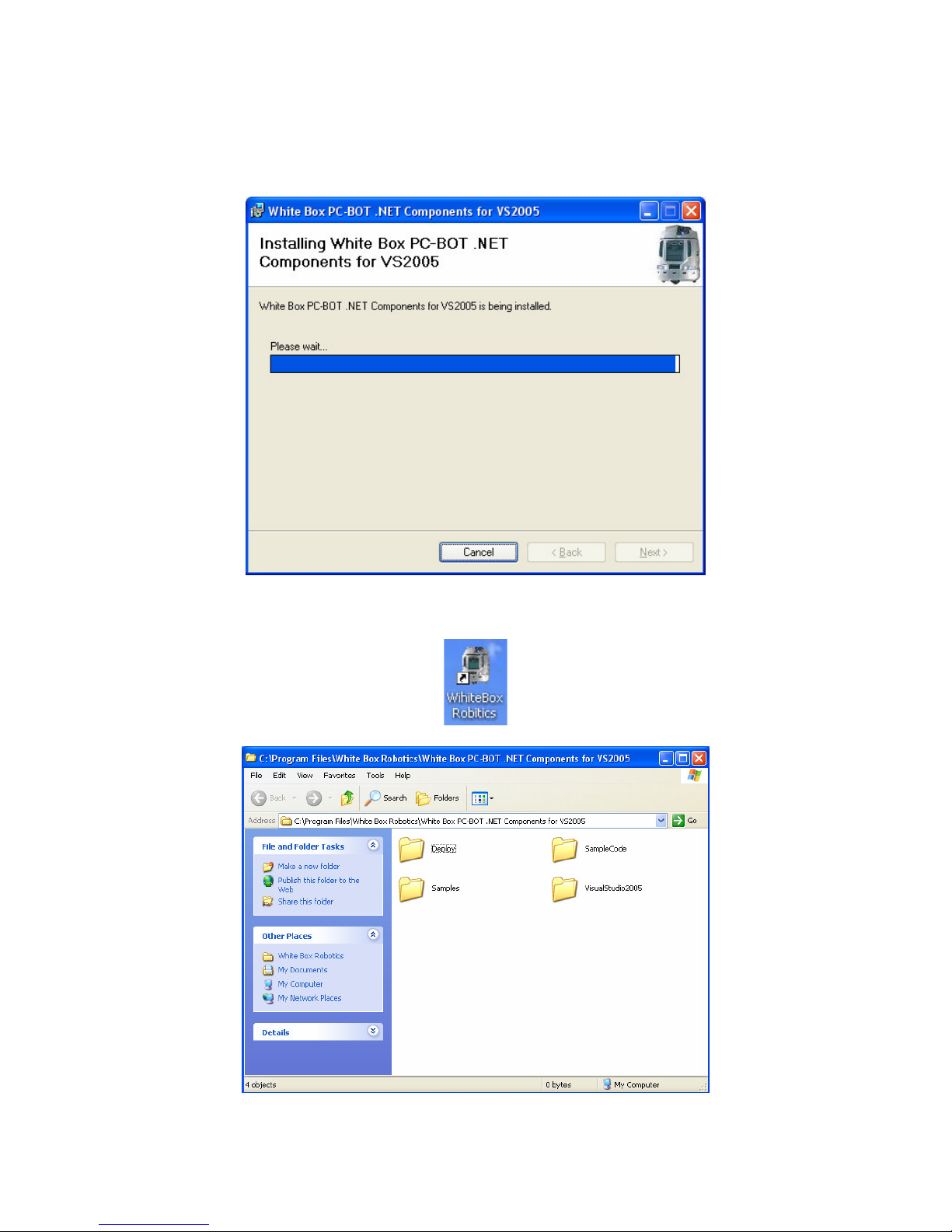
Unless it is already installed, download and install the PC-BOT dotNET Setup.msi package from the
White Box Robotics webpage.
When the installation is finished you will find a desktop icon and Start – Programs group has been
created. These are shortcuts to the sample software projects that were created in Visual Studio.
© Copyright 2006-2007 White Box Robotics Inc. and Frontline Robotics Inc
Page 18
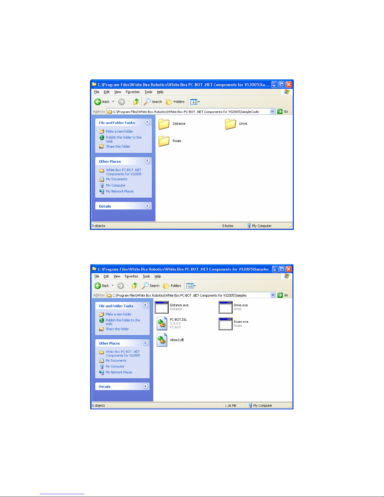
The SampleCode folder has the sample Visual Studio projects:
Distance – Used to move the robot set distances and rotate set degrees
Drive – Used to drive the robot by clicking and dragging with the mouse on the robot.
Roam – Used to demonstrate the automatic avoid movement using the IR sensors.
The Samples folder has the .EXE applications created after building the Visual Studio projects. Just
double click to open them.
© Copyright 2006-2007 White Box Robotics Inc. and Frontline Robotics Inc
Page 19
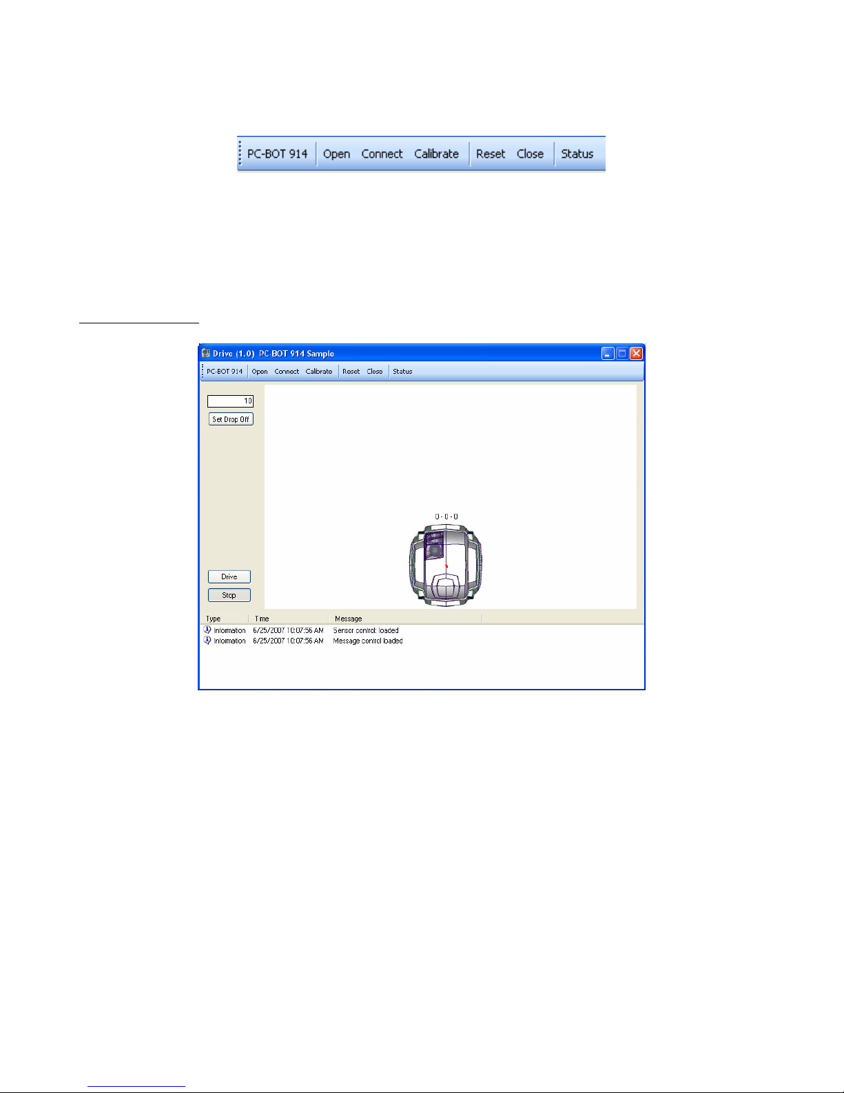
After running any of the applications, the user must first ‘Open’ the M3 module, then ‘Connect’ to the
M3 module BEFORE driving the robot.
‘Reset’ will reset the counted steps on the motor axis (i.e. reset the virtual encoders), and ‘Close’ will
close the M3 module, requiring that ‘Open’ be used again to command the M3.
‘Calibrate’ will calibrate the downward looking sensors for the ground type and colour the robot is
driving on and help with drop-off detection.
‘Status’ will list the status of the M3 module.
Drive Application
NOTE: Once the downward looking sensors are calibrated for the floor type, the ‘Drop Off’ can be
used to detect a step or hole in front of the robot. This setting can be adjusted for the operating
environment. If you want to test the robot on a desk where the drop off would be very large, you will
need to set this setting to the maximum which is 99, otherwise the robot will refuse to move forward
and will constantly tell you there is drop in front of the robot.
© Copyright 2006-2007 White Box Robotics Inc. and Frontline Robotics Inc
Page 20
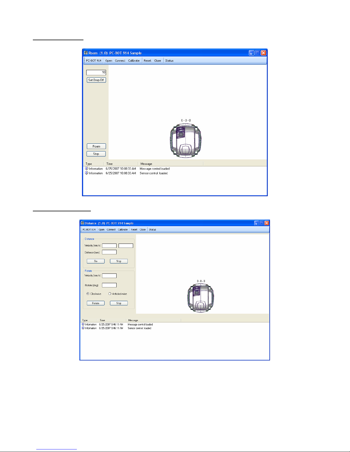
Roam Application
Distance Application
© Copyright 2006-2007 White Box Robotics Inc. and Frontline Robotics Inc
Page 21
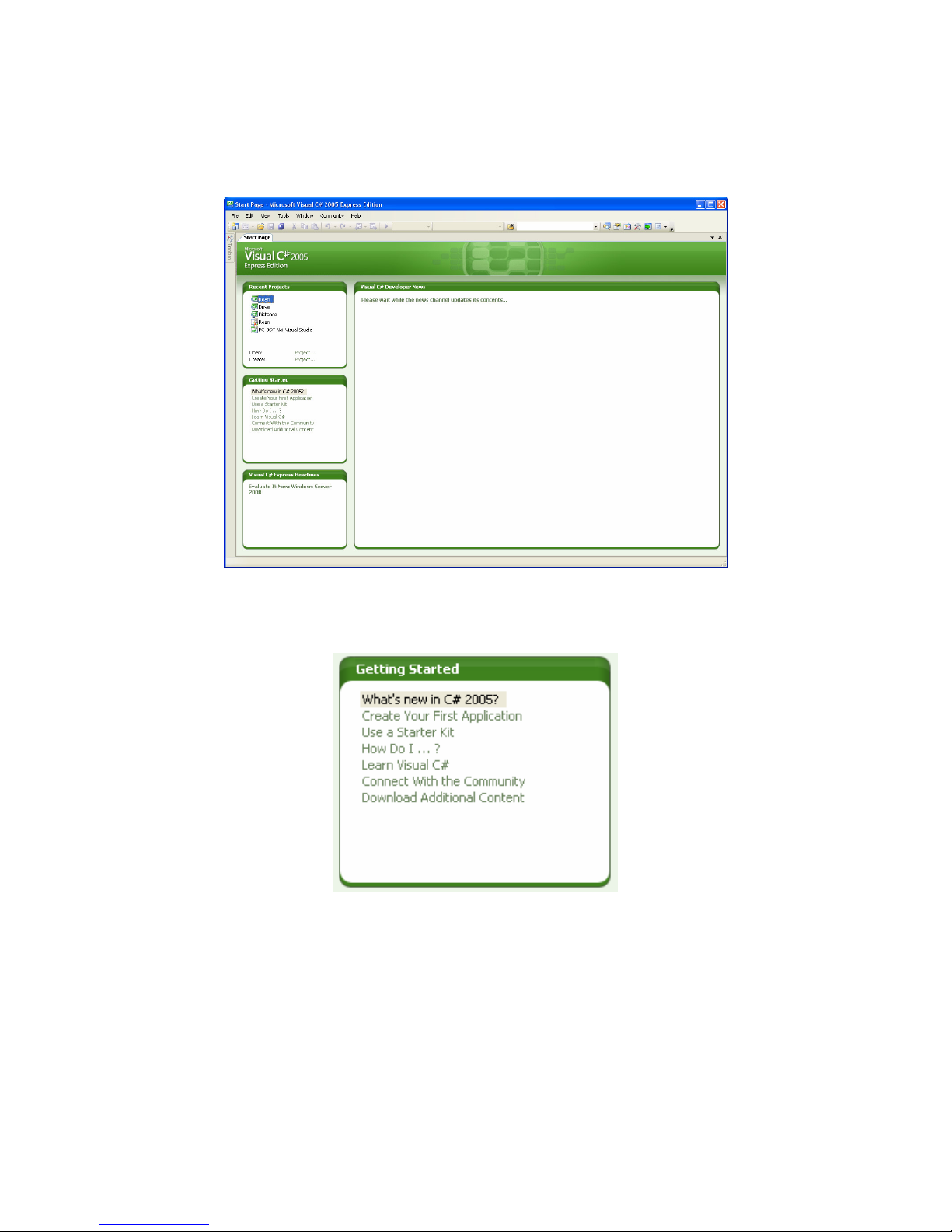
Step 4
Open the ‘Microsoft Visual C# Express Edition’ from Start All Programs.
To learn about developing Visual C# projects/applications there are a few resources you can use to
learn. The ‘Getting Started’ section after opening Visual C# Express Edition has a number of links.
© Copyright 2006-2007 White Box Robotics Inc. and Frontline Robotics Inc
Page 22
The Microsoft webpage also offers many learning tutorials for Visual Studio, see:
http://msdn.microsoft.com/vstudio/express/beginner/
Step 5
Click on the Toolbox tab on the left side of the screen. It will expand but be empty to begin with.
© Copyright 2006-2007 White Box Robotics Inc. and Frontline Robotics Inc
Page 23
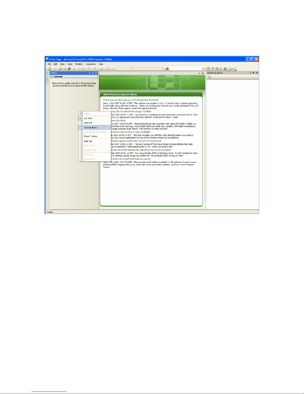
Step 6
Right click on the grey area of toolbox window, opening a menu and select ‘Choose Items…’
© Copyright 2006-2007 White Box Robotics Inc. and Frontline Robotics Inc
Page 24
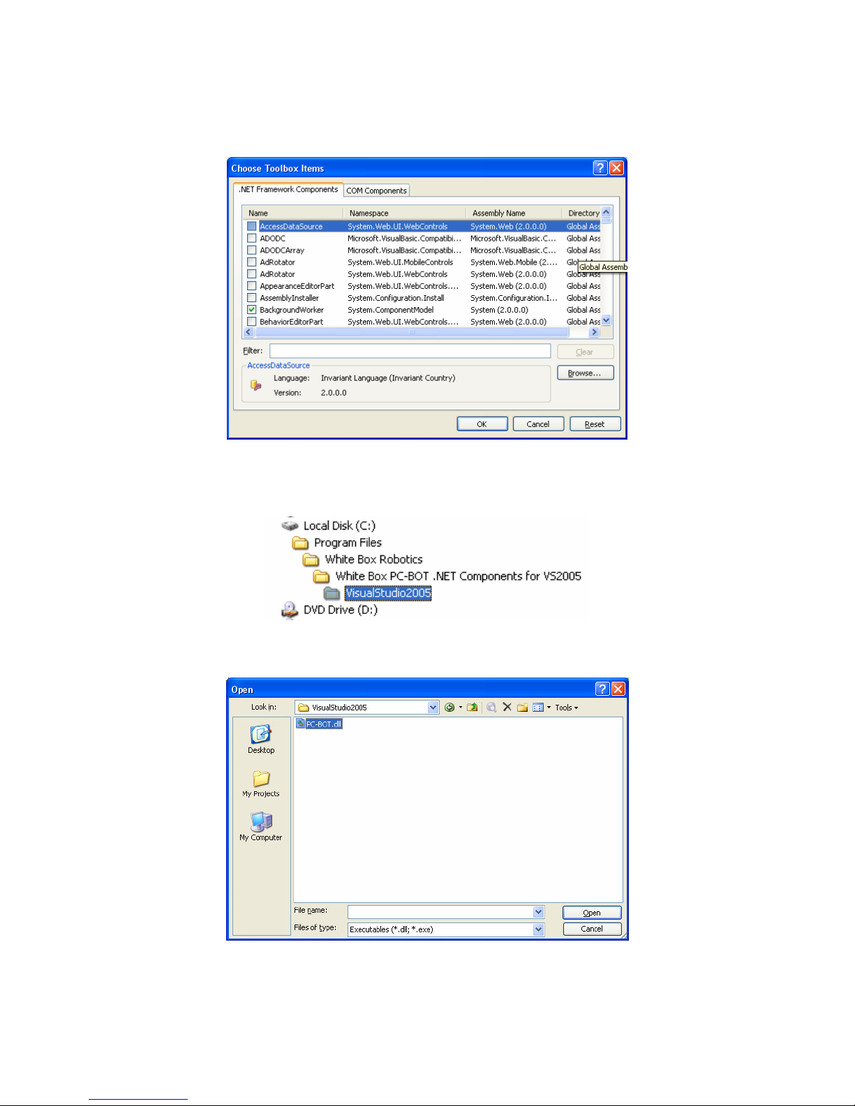
Step 7
Under the .NET Framework Components tab, click the ‘browse’ button.
Go to C:\Program Files\White Box Robotics\White Box PC-BOT .NET Components for
VS2005\VisualStudio2005\
Choose the PC-BOT.dll and click ‘Open’.
© Copyright 2006-2007 White Box Robotics Inc. and Frontline Robotics Inc
Page 25
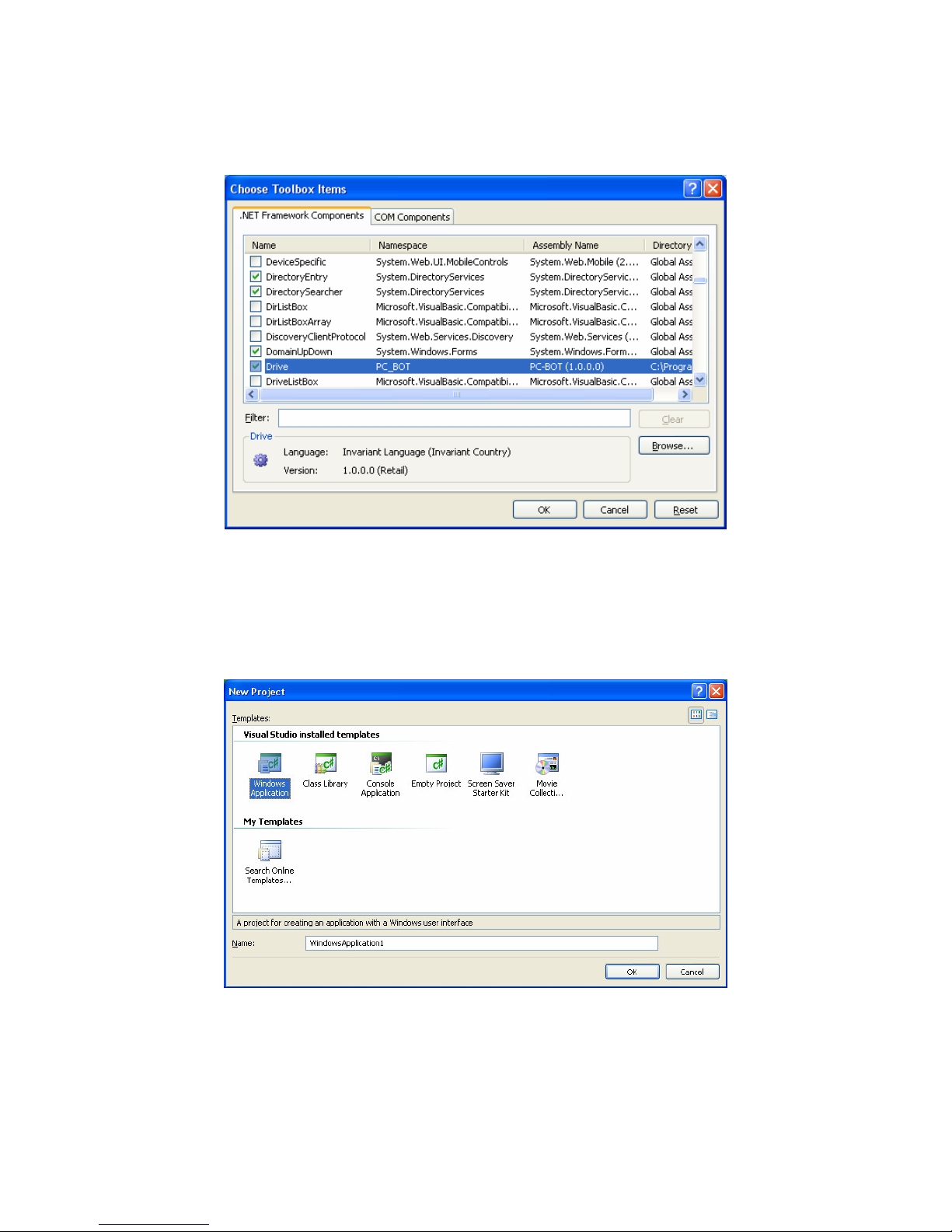
Step 8
You should see one of the PC-BOT .NET components highlighted after clicking ‘Open’
Click OK as all the PC-BOT components to the Visual Studio Toolbox.
Step 9
Start a new Visual Studio project. In the menu bar, go to File New Project.
Choose the ‘Windows Application’ template and click OK.
© Copyright 2006-2007 White Box Robotics Inc. and Frontline Robotics Inc
Page 26
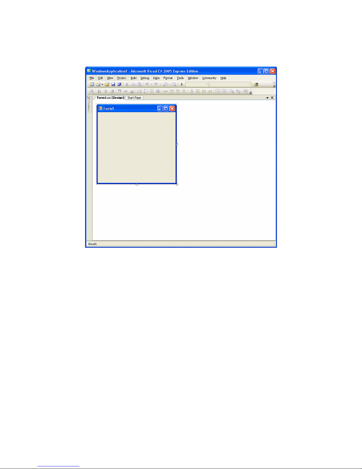
Step 10
You should see the following Windows Application window which will be initially empty.
© Copyright 2006-2007 White Box Robotics Inc. and Frontline Robotics Inc
Page 27
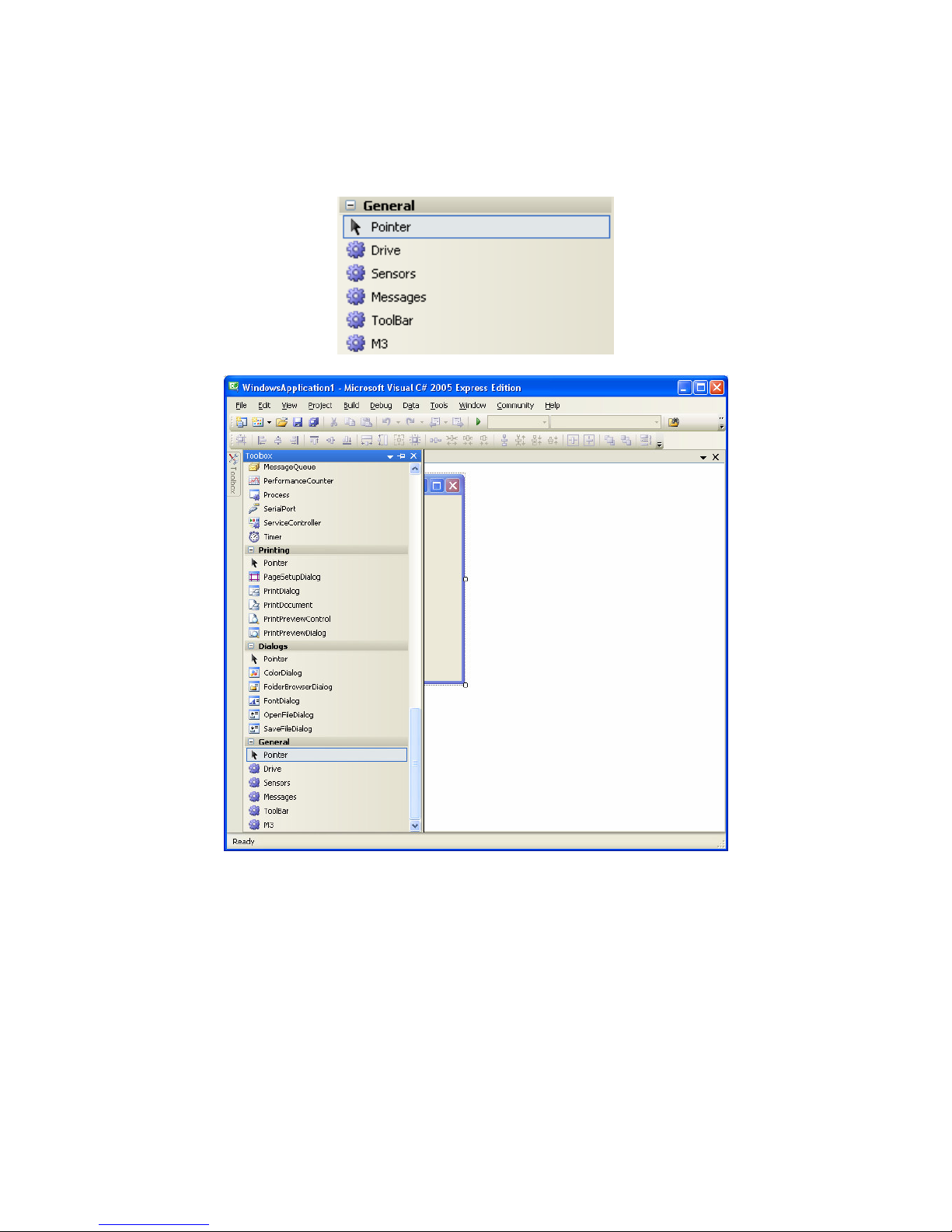
Step 11
Click on the Toolbox tab on the left side of the screen, it should be full of components to build your
applications. Scroll to the bottom where you will find the PC-BOT components.
© Copyright 2006-2007 White Box Robotics Inc. and Frontline Robotics Inc
Page 28
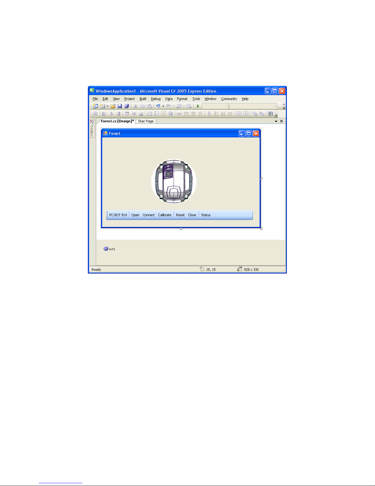
Step 12
Drag and drop any of the PC-BOT components to the Windows Application Form screen and see what
happens. For this example application the ‘Drive’, ‘Toolbar’ and ‘M3’ components were put in the
Form.
© Copyright 2006-2007 White Box Robotics Inc. and Frontline Robotics Inc
Page 29
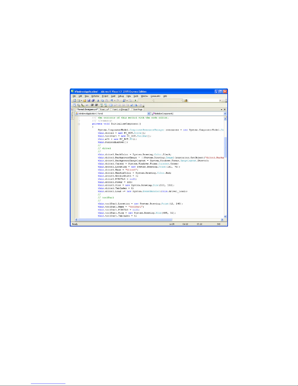
Step 13
You can select any of the components in the Form page and either double-click on them or right click
once and choose ‘View code’ to see the underlying code. The user will need to go through the tutorials
listed before in this guide to understand how this works and how to develop your own code.
The user should also read the PC-BOT_914_dotNET_v1.0.pdf document found on the White Box
Robtics Webpage as a technical guide to the PC-BOT .NET components specifically.
© Copyright 2006-2007 White Box Robotics Inc. and Frontline Robotics Inc
Page 30
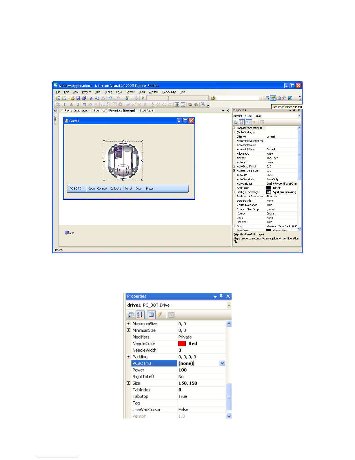
Step 14
Click on the ‘Form1.cs[Design]*’ tab to return to the GUI view of the components. Click on the
‘Properties Window’ button in the upper right side of the window to display the properties of any of
the selected components.
On EACH of the components you put in the Form1 windows, you need to connect them to the M3
component. In the ‘Properties Window’ scroll down until you see “PC-BOTm3”. By default it is set to
(none).
© Copyright 2006-2007 White Box Robotics Inc. and Frontline Robotics Inc
Page 31
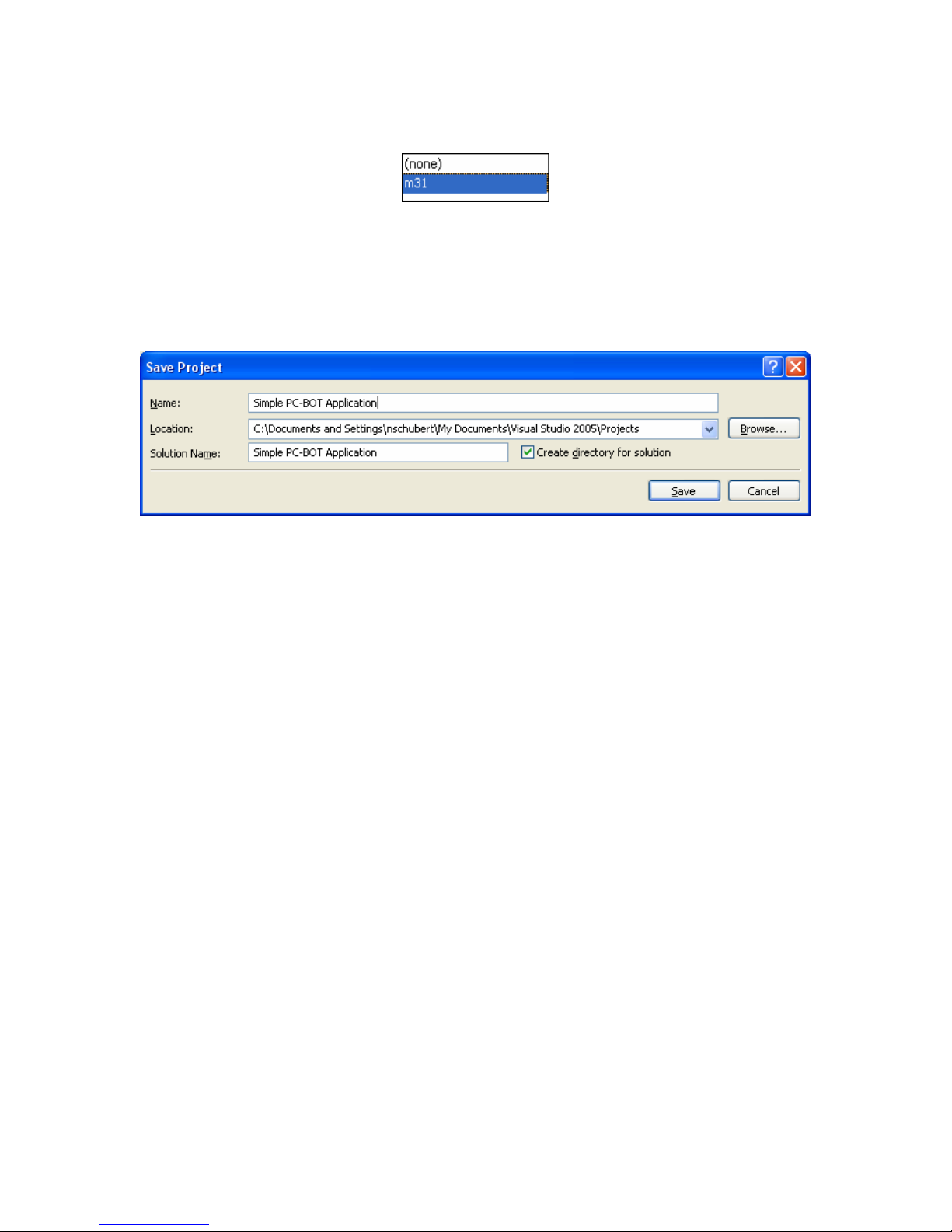
Click on the ‘none’ and change it to ‘m31’.
Step 15
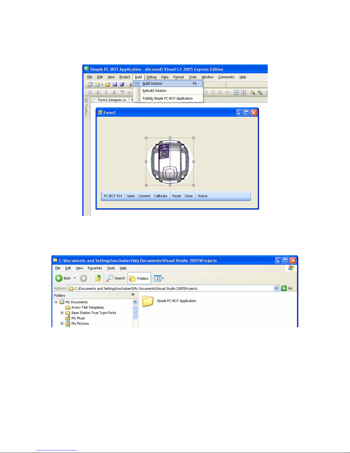
Now let’s build the example project. First save the project, go to the menu bar File Save All.
Choose a name for your application such as ‘Simple PC-BOT Application’.
Notice where the project will be built and choose a different location if you want. Click Save.
© Copyright 2006-2007 White Box Robotics Inc. and Frontline Robotics Inc
Page 32
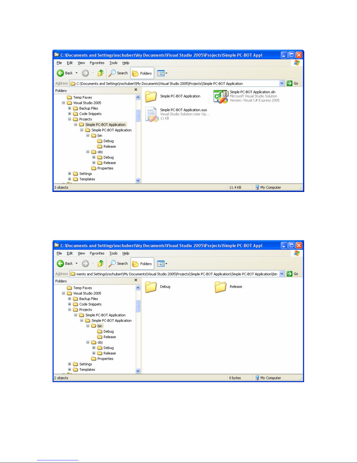
Step 16
In the menu bar of Visual Studio Express, choose Build Build Solution.
Step 17
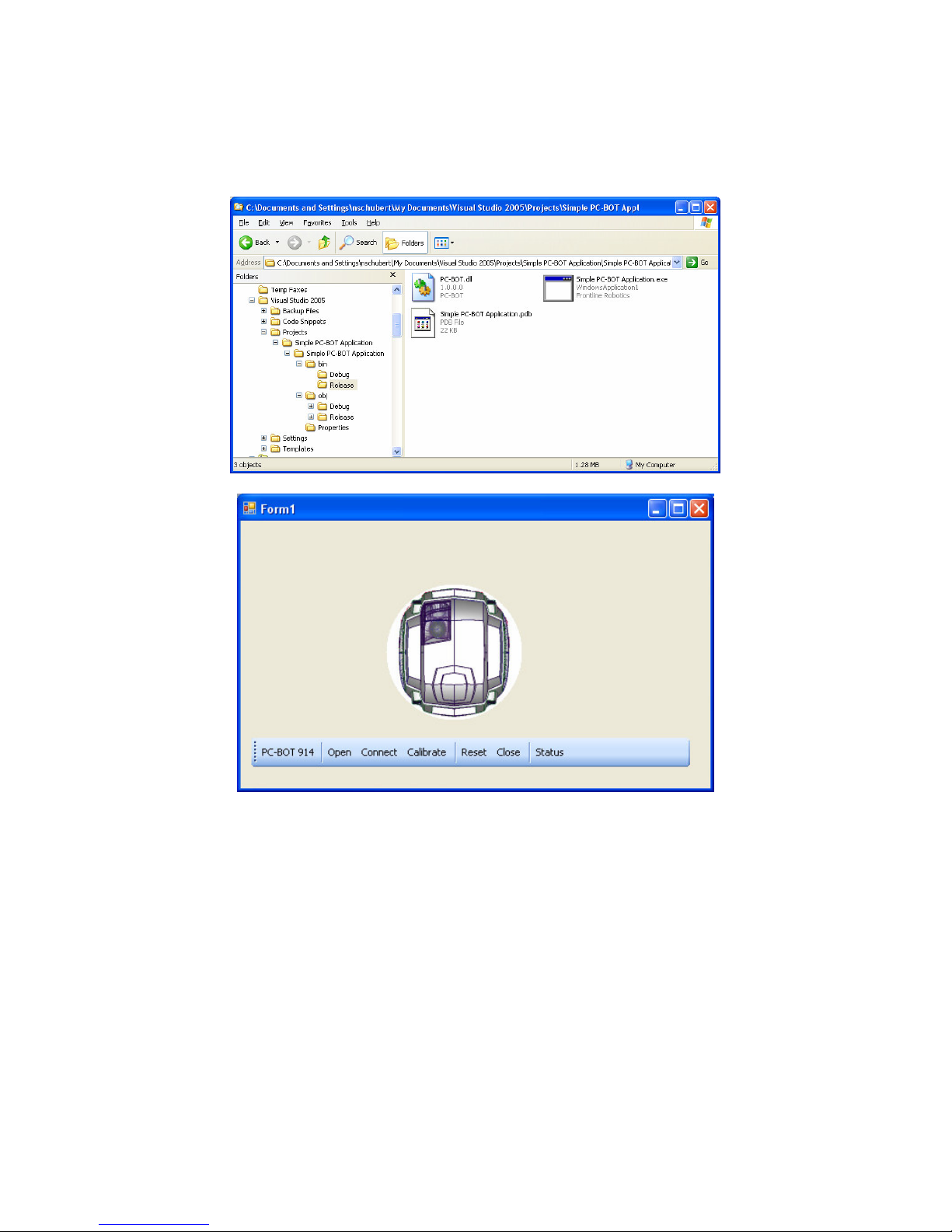
Open a folder up and go to the location where you saved the project.
© Copyright 2006-2007 White Box Robotics Inc. and Frontline Robotics Inc
Page 33
Open the Simple PC-BOT Application folder and see the project files and folders within.
Step 18
Open the next ‘Simple PC-BOT Application’ folder and then the ‘bin’ folder. You will see a Debug
and Release folder.
© Copyright 2006-2007 White Box Robotics Inc. and Frontline Robotics Inc
Page 34
Step 19
Open the ‘Release’ folder and you will find the newly created Simple PC-BOT Application. Double
click it to view and use it.
© Copyright 2006-2007 White Box Robotics Inc. and Frontline Robotics Inc
Page 35
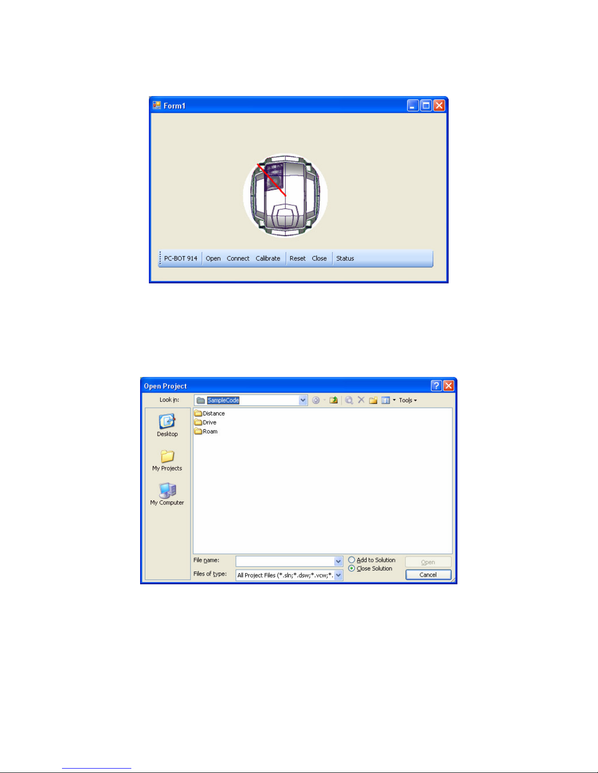
Same as with the sample applications included with the PC-BOT .NET components installed, you will
need to first click on ‘Open’ then ‘Connect’ before trying to drive your robot motors by clicking and
dragging the PC-BOT image.
Step 20
Open the PC-BOT Visual Studio Express sample projects in the menu bar by File Open Project…
Go to C:\Program Files\White Box Robotics\White Box PC-BOT .NET Components for VS2005\
folder
© Copyright 2006-2007 White Box Robotics Inc. and Frontline Robotics Inc
Page 36
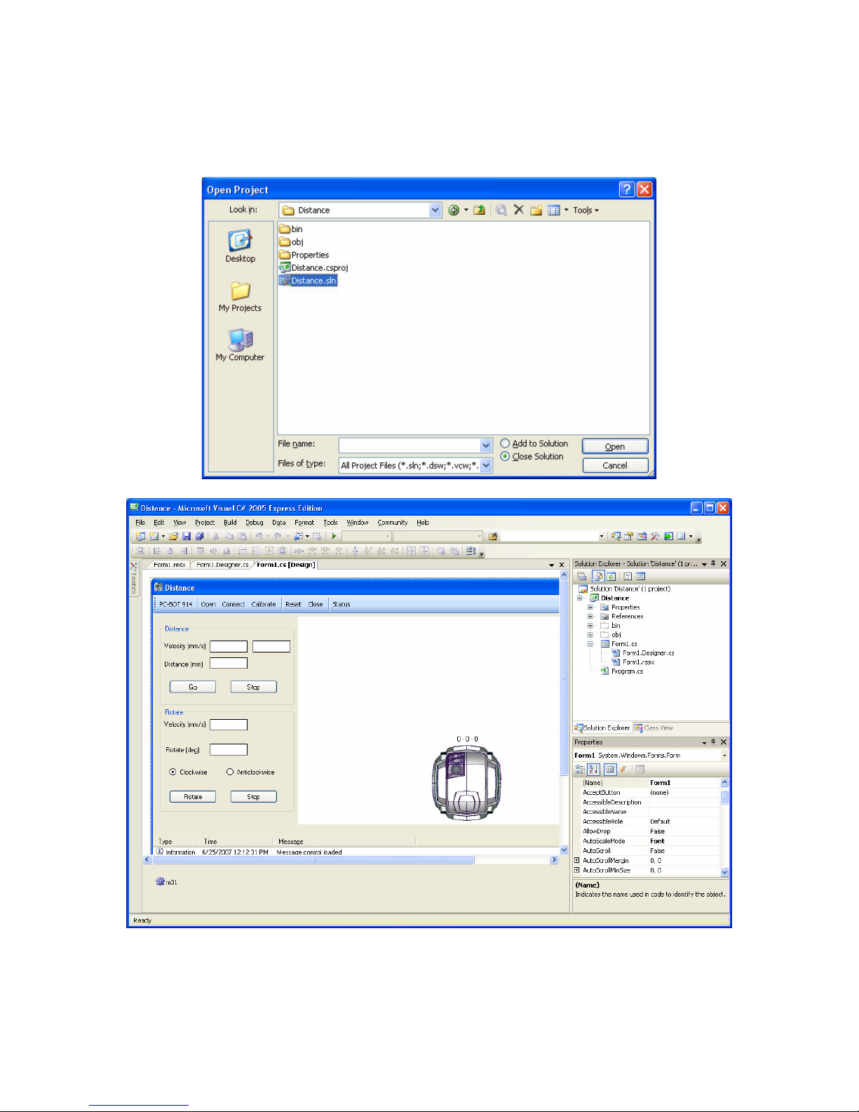
Step 21
Open any of the folders listed, so for example open the ‘Distance’ folder. Select the ‘Distance.sln’ file,
and click Open.
© Copyright 2006-2007 White Box Robotics Inc. and Frontline Robotics Inc
Page 37
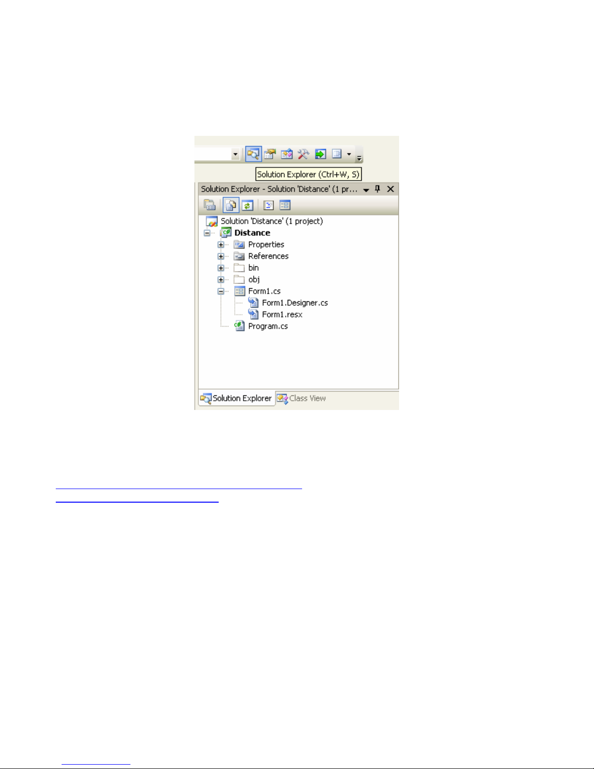
Step 22
Sometimes the Form tabs do not open automatically when the project is opened. Click on ‘Solution
Explorer’ in the top right part of the window and right click and open any of the Form1.cs and listed
files to open them.
In order to truly understand these sample applications the user will have to go through the
online tutorials from Microsoft for Visual Studio as well as the technical documents listed on the
White Box Robotics webpage.
http://msdn.microsoft.com/vstudio/express/beginner/
http://www.whiteboxrobotics.com/
© Copyright 2006-2007 White Box Robotics Inc. and Frontline Robotics Inc
Page 38
Controlling the PC-BOT using RealVNC
Step 1: Plug in the battery charger, monitor, keyboard and mouse into the robot and turn it ON.
Step 2: Plug in the wireless USB Network Adapter that came with the robot.
Step 3: Once Windows has loaded setup the wireless connection for use with your own router. If
possible assign a fixed IP address to the robot so that you will know which one to type in when using
RealVNC to remote desktop into it.
Step 4: Install the complete RealVNC application from
http://www.realvnc.com/products/free/4.1/download.html onto the robot computer.
During installation setup the VNC server with whatever settings and passwords you like.
Step 5: Once you know what IP address will be used, disconnect monitor, keyboard and mouse but
leave the battery charger attached until you actually want to drive the robot.
Step 6: Install the complete RealVNC application from
http://www.realvnc.com/products/free/4.1/download.html onto the controlling computer (your
computer). (The robot which already has the RealVNC application installed on it will act as a server
once the robot’s power is turned ON.)
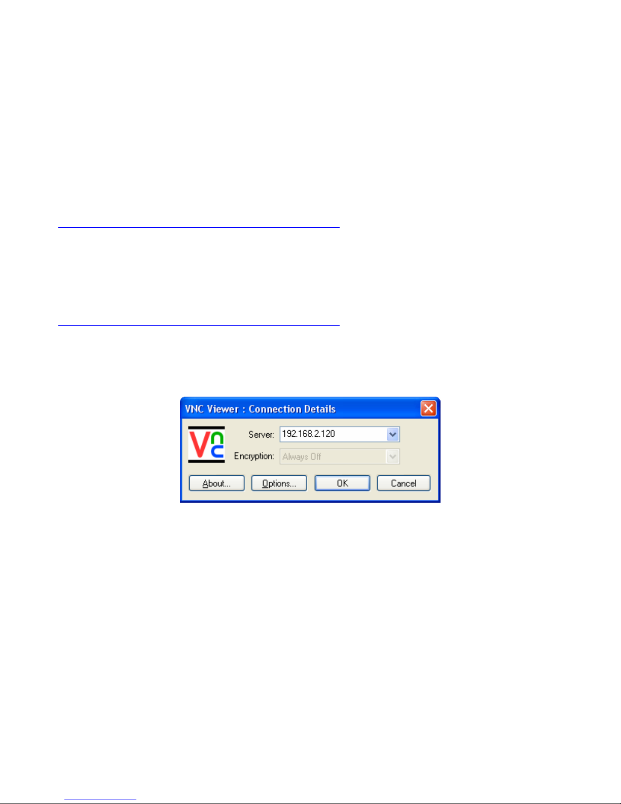
Step 7: Go to ‘All Programs’ -> RealVNC -> VNC Viewer 4 -> Run VNC Viewer
Step 8: Choose ‘OK’ after selecting the correct IP Address (use the IP address of the wireless device
on the robot).
Step 9: You should see the windows desktop of the robot. You can run any of the applications keeping
in mind the delay when displayin graphics or video.
Step 10: Make sure the robot is in a safe place before proceeding with running applications that cause
the robot to drive.
NOTE: As environments and lighting can vary so much, we cannot guarantee
proper operation when the robot is moving autonomously. Care should be taken to
ensure its safety.
© Copyright 2006-2007 White Box Robotics Inc. and Frontline Robotics Inc
Page 39
Reference Documents and Web links for Microsoft Visual Studio and .NET
Microsoft Visual Studio Webpage:
http://msdn2.microsoft.com/en-us/vstudio/default.aspx
Microsoft Visual Studio Express (free version) Webpage
http://msdn.microsoft.com/vstudio/express/default.aspx
Microsoft Visual Studio Express tutorials and documentation
http://msdn.microsoft.com/vstudio/express/beginner/
White Box Robotics .NET Support section
http://www.whiteboxrobotics.com/PCBOTs/support_dotnet.html
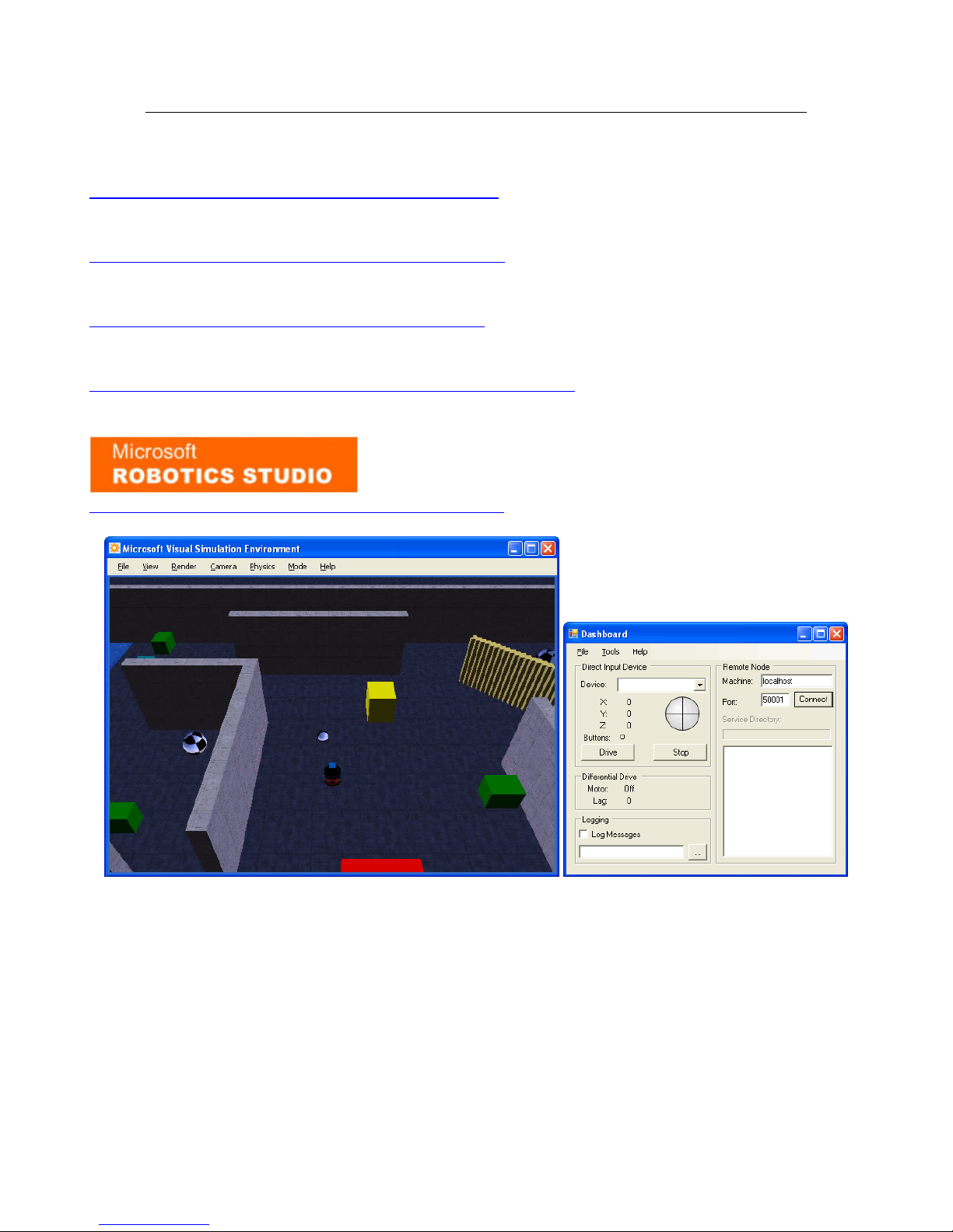
Microsoft Robotics Studio webpage
http://msdn2.microsoft.com/en-us/robotics/default.aspx
© Copyright 2006-2007 White Box Robotics Inc. and Frontline Robotics Inc
 Loading...