

Page 1

OWNER’S MANUAL
XTR-325/425/560
Total Band Protection™Plus Ku
LASER-RADAR
DETECTOR
The Whistler Group Corporate Headquarters
13016 N. Walton Blvd. ï Bentonville, AR 72712
Tel 479.273.6012 ï Fax 479.273.2927
Customer Return Center
1201 N. Dixieland Rd. ï Rogers, AR 72756
Customer Service Tel 800.531.0004
www.whistlergroup.com
P/N 260015, REV2 ©2006 The Whistler Group, Inc.
Dear Whistler Owner,
If you have questions concerning the operation of
this Whistler product please call:
C
uSTOmer SeRVICE
1-800-531-0004
Monday - Friday ï 8:00 am - 5:00 pm CT
or visit our website
www.whistlergroup.com
Please keep the receipt in a safe place. You may register your product online
warranty
verification purposes, a copy of your dated
store receipt must still accompany any unit sent in for
warranty work. If the unit is returned without a dated
store receipt an out of warranty service charge applies.
YYoouurr wwaarrrraannttyy ppeerriioodd bbeeggiinnss aatt tthhee ttiimmee ooff ppuurr--
Note:
cchhaassee.. TThhee wwaarrrraannttyy iiss vvaalliiddaatteedd oonnllyy bbyy tthhee ddaatteedd
s
sttoorree rreecceeiipptt!!
number of the unit in the space provided in the warranty section of the manual.
Now is the time to record the serial
To fully acquaint yourself with the operation of your
Whistler and to better understand the differences
between detecting radar, laser and safety radar signals, we recommend reading this entire manual or
visit our FAQ page on our website www.whistlergroup.com
Enjoy your Whistler detector and please drive safely.
Sincerely,
The Whistler Group, Inc.
at www.
wwhhiissttlleerrggrroouupp..
com. For
Model Features Summary .................... 2 - 3
Installation ........................................... 3 - 5
ïChanging T rim Rings 3 - 4
ïMounting Guidelines 4
ïW indshield Mounting 5
ïPower Connection and Fuse Replacement 5
Operation .......................................... 5 - 14
ïPr ogrammable Text Display 5
ïPr ogrammable Audio Tones 6 - 8
ïPower On and Self-T est 8
ïSetting Saver 8
ïFeatur e Engaged Confirmation 8
ïAudio Level Adjustment 8
ïAuto Quiet Mode 9
ïQuiet Mode 9
ïT each/Tutorial Mode 9
ïHighway Mode 9
ïCity/City 1/ City 2 Mode 10
ïEngaging/Disengaging VG-2 10
ïBacklight Setting 11
ïDim/Dark Mode 11
ïIntelli-cor dô 12
ïBattery Saver Mode 12
ïExternal Audio Jack 12
ïOption Select Mode 1 3
ïStay Alert Feature 14
Safety Warning System™ ......................... 14
POP™Mode Alerts ................................. 15
Laser/Radar Alerts ................................. 15
ïSpeed Radar Audio/Visual Alerts 15
ïLaser Audio/V isual Alerts 15
ïPulse Pr otection
VG-2 Alerts ............................................ 16
ïAlert Priority 16
Reset Features ....................................... 16
Troubleshooting Guide .......................... 17
Care and Maintenance ........................... 18
Are Detectors Legal? ............................. 18
FCC Information ..................................... 19
Speed Monitoring ............................ 19 - 22
ïRadar Facts 19
ïPOPôMode 19
ïT otal Band Protection
ïLaser Facts 20
ïOther Speed Detection Systems 21 -22
Warranty Information ....................... 22 - 25
Specifications ......................................... 25
Accessories ............................................ 26
Æ
ô
15
20
Page 2
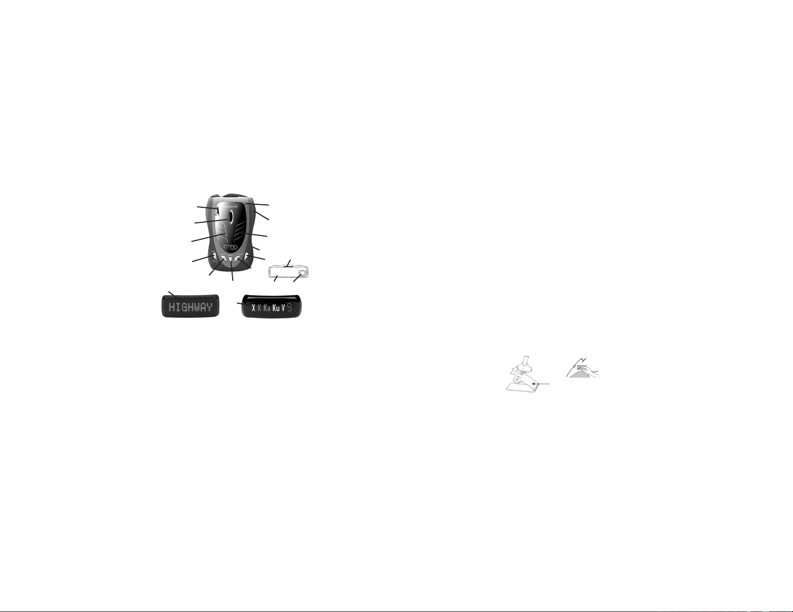
WHISTLER FEATURES FEATURE DESCRIPTIONS
XTR-325/425/560
6
1
2
9
10
12a
Accessories:
Windshield Bracket Kit, Straight Power Cord & 2 Trim Rings
FEATURE DESCRIPTIONS
NOTE: Not all units share all the features listed
Whistler’s ergonomic and user-friendly design pro-
vides a new level of operating convenience.
Special features include:
1. Bracket Release Button – Provides quick and
easy release of the mounting bracket.
2. Speaker – Provides distinct audio warnings for
X, K, Ka, Ku band radar, safety radar, laser and VG-2.
3. Mounting Bracket Location – Slot holds
mounting bracket firmly.
4. Radar Antenna – Compact, high-efficiency
antenna receives radar signals.
5. Front Laser Antenna – High gain optical lens
provides increased sensitivity and field of view for
leading-edge laser detection
8
12b
2
14
13
16
15
3
7
11
5
4
XTR-325XTR-425/560
6. Rear Laser Antenna – An integrated optical
waveguide provides superior detection of laser
signals transmitted from behind.
7. City Button - Reduces the annoyance of false
alerts typically encountered in urban driving areas.
8. Quiet/Menu Button - Pressing QUIET before a
signal is detected engages Auto Quiet Mode.
Pressing QUIET during a radar/laser encounter
silences audio alerts.(Pressing and holding for 2
seconds allows you to enter Option Select Mode—
see page 13)
9. Power/Dim -Turns unit on/off and engages
Backlight settings (press and hold).
10. Volume Down Button – Adjust volume down.
11. Volume Up Button – Adjust volume up.
12a. Blue Backlit LCD Programmable Text
Display – Provides distinct visual confirmation of
signals detected, signal strength, and indicates
engaged modes of operation.
12b. Seven Segment Icon Display – Provides band
and numeric signal strength indicators
13. Power Jack – Provides connection for the power
cord.
14. Removable Trim Ring – Allows changing the trim
ring to one of the other colors.
15. External Audio Jack – Permits easy connection of
an external speaker/headset to the XTR 560.
16. Microphone – Allows recording of audio tones in
model XTR-560
INSTALLATION
Trim Ring Removal/Installation
To change the trim ring to another color, follow
these simple steps:
Removal
• Locate the tab on the trim ring at the top of
the mounting bracket location.
• Using your fore finger, lift up on the trim ring
and the ring will pop out.
34
Installation
INSTALLATION
• Locate the tab near the button openings and
insert this end first into the unit.
• Gently snap in the other tabs as you work your
way to the back of the unit.
Mounting Guidelines
• Mount the unit as low as possible near the center
of the windshield.
• Do not mount your unit behind wipers,
ornaments, mirrored sunscreens, etc. These
obstructions have metal surfaces which can affect
radar and laser signals and reduce critical warning
time. (Regular tinted glass does not affect
reception.)
• Some windshields have an Instaclear™or
Electriclear™type coating, which affect radar signals.
Consult your dealer or the vehicle’s owner’s manual to
determine if your windshield has this coating.
• Avoid placing unit in direct contact with windshield.
• Avoid placing unit in direct sunlight.
• To reduce the possibility of theft, conceal your
unit when not in use.
Windshield Mounting
• Install the two suction cups and rubber bumper
onto the bracket by fitting them into their holes.
Windshield
Mounting
Rubber Bumper
Press the suction cups onto the windshield at the
•
location you have chosen.
• Slide the detector onto the bracket until it locks into
place.
• If necessary, the unit may be leveled by bending the
windshield bracket.
• Press the bracket release button and remove the
detector before bending.
Page 3

Power Cord Connection
• Plug the small end of the power cord into the
unit’s power jack.
• Plug the large end into the vehicle’s cigarette lighter.
NNoottee::
The cord fits tightly into detector. When
installing the cord, expect some resistance.
Fuse Replacement
The lighter socket plug is equipped with a
replaceable 2 amp 3AG fuse located behind the
silver tip. To replace the fuse, carefully unscrew
the tip of the plug.
IImmppoorrttaanntt::
spring which may fly out when disassembling.
Insert the new fuse with the spring and screw on
the tip. With use, the screw cap on plug may
loosen. Retighten it occasionally.
Unscrew the tip of the lighter socket plug
carefully when replacing the 2 amp fuse.
Unscrew slowly. The tip contains a
OPERATION
Programmable Text Display
(XTR 425/560 only)
The above models have the ability to modify the
standard laser/radar detector’s display.
“WHISTLER”, “HIGHWAY”, “CITY”, “CITY 1”,
and “CITY 2” can be changed to display your
name, or any combination of 8 characters. For
example, “HIGHWAY” can be changed to “GO
4 IT”.
Note: A space is counted as a character.
WARNING!!! Programming the text display or
the audio is not intended to be done while you
are driving. You should not use any device in a
vehicle that may distract you from observing the
road ahead.
56
INSTALLATION
To Modify the Text
OPERATION
• Press and hold the Quiet button to enter
Option mode (see page 13 ). Once “USER
TEXT” is displayed simultaneously press and
release the VOL UP and VOL DOWN buttons
each time to scroll through the text that can
be customized. When a text is selected, (use
WHISTLER for example) the display will
indicate “WHISTLER” with a blinking cursor
under the letter “W”.
Note: The blinking cursor indicates that this is
the first letter ready to be changed.
• Press the Volume Up button to advance to the
next letter/character/symbol/space to be
displayed.
• Press the Volume Down button to select the
previous letter/character/symbol/space to be
displayed.
• Press the Quiet button to advance to the next
position in the current word.
• Press the City button to go back to the previous
position in the current word
• Press and hold the City button to change the
character set (A, a, 9, ! etc.).
• Press PWR to exit User Text Mode and return to
OPTION Mode.
• Press PWR again to exit OPTION Mode.
Programmable Audio Tones
Model XTR 560 also has the ability to modify the
standard laser/radar detector’s audio tones. Audio
tones such as “X Band”, “K Band,” “Ka Band” “Ku
Band” and “Laser” can be changed to play up to 15
seconds of a favorite tune, phrase, saying, almost
anything you like. When the unit detects K band, for
example, the K band voice will now be followed by
what was recorded for K band.
TIP: Turn off the voice option to have the unit
respond only with the custom recorded alerts.
(XTR 560 Only)
To Modify the Audio, Part 1
OPERATION
• Press and hold the Quiet button to enter Option
Mode (see page 13 ). Once “USER TONE” is
displayed, simultaneously press and release the
VOL UP and VOL DOWN buttons to allow for
selection of Normal Tones or Custom Tones.
(Display shows “ X - Norm” or “ X - Cust”) The
Vol Up button selects Custom Tone and Vol Down
button selects Normal Tone. The Quiet button
advances the menu to the next band selection.
“X - Norm”—› “K - Norm”—› “Ka - Norm” —›
“Ku - Norm” —› “L - Norm”
The PWR button exits User Tone Mode, but still
remains in Option Mode. Press the PWR button
again to exit Option Mode.
To Modify the Audio, Part 2
IMPORTANT: Unit does not detect radar or
laser signals during recording or while playing a
tone.To ensure a quality recording, the source
should be approximately 1” away from the
microphone.
To record or play a message (Record/Playback
Mode):
• Press both volume buttons for less than 2
seconds and release. The unit will beep once;
this enters Custom Mode. Display shows: CUSTOM
The display shows the word PLAY and REC
with accompanying arrows to indicate the
buttons to control these functions (Start/Stop
Play = PWR and Start/Stop Rec = City).
• The display then indicates: CUST--X as X is the
first band ready to record up to 15 seconds of
audio.
• Press and release the Quiet/Record button
advances the recording feature to the next
band.
• Press both volume buttons for less than 2
seconds and release to exit Record/Playback
mode.
7
Page 4

NOTE: Custom Mode automatically exits within 20
OPERATION
seconds if a button is not pressed. Messages are
kept in memory and are not affected by resetting
the factory features. See “Reset Features” section of
the manual.
To delete a message:
• Enter Custom mode and press Volume Up or
Volume Down button until selected band
appears on the display.
• Press the Quiet/Record button twice.
TIP: To prevent the recording of the stop button
press (click), allow the recording process to continue
for 15sec and automatically time out.
Power On and Self-Test
Each time your Whistler detector is turned on,
an automatic self-test sequence confirms that
the speaker and visual displays are functional.
• Press Power. Display shows in order:
1. WHISTLER 2. X-Band 3. K-Band 4. Ka-Band
5. Ku-Band 66.LASER 7. POP ON 8. VG2 OFF
9. SR OFF 10. Highway
• Display indicators will illuminate in the same order
on the XTR-325
Setting Saver
Setting Saver saves your personalized settings
so that when the detector is turned off and then
on again, you do not have to re-enter them.
Feature Engaged Confirmation
Each time a button is pressed, one beep confirms
feature “on”, two beeps confirm feature “off”.
Audio Level Adjustment
The audio levels can be adjusted high to low or
low to high.
• Press Volume up to increase audio level.
• Press Volume down to decrease audio level.
As audio level is adjusted, beeps are provided
and the display indicates volume level.
8910
Auto Quiet Mode
OPERATION
Auto Quiet reduces the selected audio level to
level (1) approximately 5 seconds after a radar or
safety radar signal is detected. The alert for any
new signal within 20 seconds will resume at level
(1). Auto Quiet does not affect VG-2 or laser
alerts.
• Press Quiet/Menu (before a signal is detected)
to engage Auto Quiet.
• Once the Auto Quiet mode is engaged, you
may cancel the audio alarm by pressing Quiet.
• Press Quiet (when the unit is not alarming) to
cancel Auto Quiet mode.
Quiet Mode
Quiet cancels audio during an alert and any new
alert within 20 seconds. After 20 seconds,
approximately 2 beeps are provided on any new
alert and unit then remains quiet.
• Press Quiet to cancel the audio.
• Press Quiet a second time during an alert to
restore the standard audio alert pattern; or turn
the unit off, then on.
Teach/Tutorial Mode
Provides simulated alerts for each type of signal.
• Press City and Quiet simultaneously and
release.
• Display Shows: (XTR-425/560 only)
• Press Power to exit.
Highway Mode
Highway mode provides full audio warnings any
time radar (X, K, Ka, Ku, Safety Radar) or laser
signals are detected, and is recommended for
open road driving.( Highway mode lets every signal in)
For more information on City and Highway mode, please
visit our FAQ page on our website:
group.com
www.whistler-
City/City 1/City 2 Mode
OPERATION
Whistler’s Three Stage City Mode is designed to
reduce the annoyance of automatic door openers, intrusion alarms and other devices which share frequencies with police radar. Generally, X band is
used for these devices.
• Press City to cancel Highway mode and
engage City.
• Press City again to enter City 1 Mode
- display shows ‘C1 Lo X’. (XTR 425/560)
• Press City again to enter City 2 Mode
- display shows ‘C2 No X’ (XTR 425/560)
• Pressing City a fourth time cancels City 2 Mode
and returns the unit to Highway Mode.
In City Mode, weak speed/safety radar signal
give an initial alarm of two beeps, and then
remains quiet unless the signal becomes very
strong. When the signal strength increases, two
additional beeps are provided. City 1 and City 2
Modes operate the same as Highway Mode, but
in City 1 Mode, only the X band sensitivity is lowered. In City 2 Mode, X-band is not detected.
Some towns/small cities may still be
Caution:
using X band radar. City Modes do not change
the audio alert for laser or VG-2.
Engaging/Disengaging VG-2
See Option Select Mode to turn this feature
on/off. When a VG-2 signal is detected, the VG-2
alert is sounded and the display flashes “VG-2”.
After 3 seconds the audio is canceled and the
display no longer flashes. This cycle is repeated
if the VG-2 signal is again detected. During the
period a VG-2 signal is detected, a radar signal
cannot be detected. However, because the VG-2
alert has confirmed that a patrol car is nearby,
you are already aware of the potential for speed
monitoring and can adjust your speed accordingly. Laser detection is not affected while a VG-2
signal is detected.
Page 5

Backlight Setting (XTR 425/560)
OPERATION OPERATION OPERATION
The backlighting (B/L) can be programmed to
be illuminated all the time, only when alarming,
or choices in-between. The options are selectable by pressing and holding the Power/Dim
button on the unit. The options are:
OFF-OFF = B/L is off at idle and off during an alarm.
OFF-DIM = B/L is off at idle and dim during an alarm.
OFF-BRT = B/L is off at idle and bright during an alarm.
DIM-OFF = B/L is dim at idle and off during an alarm.
DIM-BRT = B/L is dim at idle and bright during an alarm.
BRT-BRT = B/L remains bright at idle as well as alarming.
Backlight will turn on, if selected, while the unit
alarms and remain on for 3 seconds after the unit
stops alarming. When any button is pressed the
backlight will illuminate at the dim setting and
remain on for 3 seconds afterwards. The backlight
will also illuminate while in option mode.
Dim/Dark (XTR-325 only)
Dim/Dark Mode reduces the illumination of the
display.
• Press and hold B/L button for 2 seconds to
reduce illumination to a Dim setting.
• Pressing and holding the B/L button for 2
seconds a second time engages Dark Mode.
The display illumination is further reduced.
Dim or dark can be engaged during an alert. In
Dark Mode, the display goes dark for as long as
a signal is being detected and for 20 seconds
after, then the display returns to the dimmer setting.
• Pressing and holding the B/L button a third
time restores full illumination to the display.
Intelli-Cord
Using Whistler’s optional Intelli-Cord™Power
Cable allows some models to control the detector’s features such as Power On/Off, City
Modes, Dim/Dark, and Quiet/Auto Quiet with a
simple press of the button on the Power Cable.
Two features can be controlled: one by a short
press of the button (S1), and the second by a
long press of the button (S2). Option Mode
allows the user to program the feature assignments.
Vehicle Battery Saver Mode
The Vehicle Battery Saver Mode automatically
shuts off your detector if you forget to turn it off.
The timer is reset if the detector is turned off,
unplugged or any button is pressed before the
timer has expired. The detector will alert you with
an audible and visual warning before it shuts off.
During this warning you can reset the unit by
pressing any button. This will reset the timer.
If the unit has automatically turned itself off, press the
Power button to turn the unit back on. You can manually engage the Vehicle Battery Saver Mode by
pressing and holding the City button until one
beep is heard. (XTR-425/560 Only)
Refer to “Option Select Mode” for instructions
for deactivating battery saver mode feature.
(XTR-425/560 Only)
XTR-325 Timer = 6 hrs, XTR-425/560 Timer = 3 hrs
External Audio Jack
The External Audio Jack can be used to connect an external speaker or headphones
in environments with high ambient noise levels.
The internal speaker will be disconnected.
™
Option Select Mode
Entering Option Select Mode allows you to customize
options such as Tone Select, Abbreviated Power Up
Sequence and VG-2 Mode. Press and hold quiet button to enter Option Select Mode. When selecting
options, the volume up , volume down or
Quiet buttons must be pressed within 20 seconds or
Options Mode will automatically be exited. To enter:
(425 & 560 only)
11 12
13
Page 6

Stay Alert Feature
OPERATION
The Stay Alert Feature is designed to test a driver’s
alertness. To engage (when unit is not alarming) :
• Press and hold City for approximately 2 seconds. Release button during or immediately after
the alert is given. Display shows:
–XTR-325 only: The “H“or “C“ will flash
Within 30-60 seconds two beeps are sounded; to
show alertness, the driver must press either the
City, Volume, or Quiet buttons within 3-5 seconds. If
a button is not pressed within 3-5 seconds, the
cycle is repeated.
If a button was not pressed within 3-5 seconds
alarm sounds and the display shows:
All LEDs flash for XTR-325
• Press Power to exit.
WARNING!!! Stay Alert is NOT intended as a sub-
stitute for adequate rest. You should NOT operate a
vehicle if you are drowsy. During extended periods of
vehicle operation, you should take frequent breaks.
Improper reliance on the Stay Alert feature may result
in vehicle damage, personal injury or death. NEVER
OPERATE A VEHICLE IF YOU ARE DROWSY.
Safety Warning System™
In communities where transmitters are located,
the Safety Warning System™displays over 60
text messages. When Safety Radar is detected
the audio alert is geiger counter-like.
NNoottee::
Safety Warning System
in Option Select Mode.
Safety Warning System Text
Example: Poor - Road - Surface.
XTR-325 displays an “S.”
Not all areas have Safety Warning System
Note:
transmitters.
™
SWS
™
is labeled “SR”
14 15
POP™ MODE ALERTS
POP™ Mode Alerts
Because POP™ Mode travels on regular radar
bandwidth, there is no particular alert for POP
Mode transmissions. POP™ Mode alerts will be
displayed as a regular radar alert.
LASER/RADAR ALERTS
Speed Radar Audio/Visual Alerts
When X, K, Ka, or Ku is detected, the band ID
and signal strength are displayed. The audio
alert is continuous and has a geiger counter-like
pattern. The faster the beep, the closer or
stronger the radar source.
Note:
Geiger not available when custom tones
are selected
Laser Audio/Visual Alerts
When a laser signal is detected, the audio alert is
continuous for a minimum of 3 seconds.
• The Displays Shows:
The more “|||”, the closer the laser source.
XTR-325 displays an “L”
Pulse Protection
Pulse (or instant-on) radar is more difficult to
detect than conventional radar because it
remains ‘off’ until activated to measure the
speed of a targeted vehicle.
When a pulse type transmission is detected, your
Whistler detector sounds an urgent 3-second
audio warning and the display shows:
XTR-325 displays an “P”
After the 3-second pulse alert, the standard alert
pattern continues for as long as the signal is
present.
It is important to respond promptly to a pulse
alert, since warning time may be minimal.
™
®
VG-2 Audio/Visual Alerts
VG-2 ALERTS
Note:
You must turn this feature on before it will
™
detect VG-2.
When a VG-2 signal is detected, the detector ‘hides’ its
own radiated signal and becomes undetectable by
the VG-2. Once VG-2 is detected,
the detector checks for a VG-2 signal. If a VG-2
signal is still present, the unit continues to hide
and repeats the VG-2 alert. If no signal is detected,
two beeps are provided, indicating an ‘all clear’ condition. During a VG-2 Alert X, K, and Ka band signal s can not be received (Reference page 21 for VG2 information).
Alert Priority
When two or more signals are received at the
same time, the alert priority is:
1. Laser 2. VG-2 3. Speed Radar 4. Safety Radar
Example: If X band is alerting, then suddenly a VG-
2 signal is detected, the VG-2 warning will override
the X band alert.
Reset Features
All user features can be reset to factory settings.
• Unplug Power Cord from unit.
• Press and hold Power and Quiet buttons.
• Plug Power Cord into unit.
• Wait for two beeps then release buttons.
Unit is now reset to the following features and settings.
Default factory settings are:
1. Audio to level (5).
2. Display shows Highway.
3. Auto Quiet Mode OFF.
4. VG-2 Detection Mode OFF.
5. Safety Radar OFF.
6. Vehicle Battery Saver ON.
7. Full Power Up sequence.
8. Default TONE 3.
9. POP ON.
10. Backlighting Dim/Bright
11. Dim/Dark to Full Bright
every 30 seconds,
16
Page 7

TROUBLESHOOTING
Your Whistler detector is expertly engineered and
designed to exacting quality standards to provide you
with reliable, trouble-free operation. If your unit has
been correctly installed following the guidelines in this
manual, but is not operating optimally, please refer to
the troubleshooting guide below.
PROBLEM: No display or audio.
• Check fuse in Whistler plug; replace if necessary with
a 2 amp 3AG type.
• Check fuse for lighter socket; replace if necessary.
• Make sure lighter socket is clean.
PROBLEM: Unit alarms when using vehicle
electrical accessories (brakes, power mirrors,
power windows, turn signals, horn, etc.)
when unit is connected to the power cord.
• Vehicle’s electrical system, including battery and
alternator, may have electrical noise. Install a filter
capacitor
(470mfd. 25 volt or larger capacitance value)
on the back of the lighter socket.
PROBLEM: Unit alarms when vehicle hits
bumps.
• Check for loose lighter socket; tighten and clean.
• Check connections at both ends of power cord.
Substitute another cord to determine if cord is
defective. Return defective cord to the factory.
PROBLEM: Audio alerts are not loud enough.
• Cancel Auto Quiet Mode or City Mode.
• Check audio level setting
PROBLEM: Unit turns itself off
• See battery saver feature on page 12
If difficulties occur which cannot be solved by
information in this Troubleshooting Guide, please
call Whistler Customer Service at 1-800-531-0004
or visit our FAQ page at
www.whistlergroup.com/faq-detectors.asp,
before returning your unit for service.
(see page 8).
CARE AND MAINTENANCE
Care And Maintenance
During the summer months, avoid prolonged
exposure to direct sunlight by removing your unit
from the dash when your vehicle is parked for an
extended period of time. Do not spray water,
cleaners, or polishes directly onto the unit. The
spray may penetrate through the openings and
damage the unit. Also, do not use any abrasive
cleaners on the unit’s exterior.
As with all battery operated devices remove the
batteries when this unit will not be used for an
extended period of time. Damage caused by
leaky or improperly charged batteries are not
covered under warranty. Check with the battery
manufacturer about the specific battery warranty.
ARE DETECTORS LEGAL?
In Most States YES!
Laser-Radar detectors are legal in every state
(with the exception of Virginia and Washington,
D.C., which have local regulations restricting the
use of radar receivers in any vehicle) when used
in automobiles or light trucks (under 10,000 lbs.).
Concerning trucks over 10,000 lbs., the Federal
Highway Administration (FHWA) issued a
regulation, effective January, 1994 which prohibits
radar and laser detector use in these types of
vehicles nationally. Prior to the FHWA regulation,
laws existed in the state of New York restricting
the use of radar detectors in trucks over 18,000
lbs. and in Illinois in trucks over 26,000 lbs.
FCC INFORMATION
FCC ID: HSXWH16
This device complies with part 15 of the FCC Rules.
Operation is subject to the following two conditions:
(1) This device may not cause harmful
interference, and
(2) this device must accept any interference received,
including interference that may cause undesired operation.
Important:
changes or modifications not expressly approved
by Whistler could void the user’s authority to
operate the equipment.
FCC requirements state that
SPEED MONITORING
Radar Facts
A radar gun operates by transmitting radio
waves at certain frequencies which reflect off
objects and are picked up by the radar gun’s
receiving section. When a radar beam reflects
off a moving target, a measurable frequency shift
occurs. The radar unit converts this shift into miles
per hour to determine your vehicle’s speed.
Currently, the FCC (Federal Communications
Commission) permits operation of traffic radar
guns at X Band (10.500 - 10.550 GHz), K Band
(24.050 - 24.250 GHz), Ka Band (33.400 - 36.000
GHz) and Ku Band (13.425 - 13.475 GHz).
Note:
A radar detector will not alarm if an officer is not transmitting on any one of the above
radar bands.
POP™ Mode
POP™Mode is a feature on some newer radar
guns operating on K and Ka bands. When the
gun is in POP™Mode and activated, a brief burst
of energy, less that 1/15 of a second, is transmitted and the vehicle’s speed is quickly acquired. A
detector without POP™Mode detection capability cannot respond to this brief transmission.
17
18
19
Page 8

SPEED MONITORING
Total Band Protection™ PLUS Ku
Complete Band Coverage that detects laser,
radar including Ku, VG-2 and safety radar bands.
Laser Facts
It’s well documented that many radar guns
cannot reliably provide the speed of a targeted
vehicle that is traveling in a group of vehicles. In
contrast, a laser gun can target a specific vehicle
out of a line of traffic and determine its speed.
The advantage of laser over radar in terms of
target identification is the result of the laser gun’s
narrow beam. A radar gun’s transmission can
cover more than a four-lane highway at a distance of 1,000 feet, compared with a laser gun’s
transmission which covers about 3 feet at the
same distance. For best protection, keep these
points in mind:
• Because the vehicle’s license plate or
headlights are the laser gun’s primary targets,
mounting the Whistler detector on the
dashboard can improve laser detection at short
range.
• Do not follow closely behind any vehicle you
cannot see through. If you can’t see past a
vehicle ahead of you, chances are your detector
won’t either.
• The receiving range of your laser detector will
not be the same as a radar detector. Laser guns
are most often used at short range.
Whistler Laser-Radar detectors receive all current
laser guns which operate at a laser wavelength of 905
+/- 10mm.
•Pro Laser
™
I II III •LT1 20-20 •Ultra Lyte
20
SPEED MONITORING
Laser Tips
If you are the targeted vehicle, a laser gun can
often determine your speed within a few
seconds after you receive an alert. In this situation there is generally no time to safely adjust
your speed. However, if you are traveling near or
behind the targeted vehicle and receive an alert,
response time should be sufficient. Any laser
alert, regardless of duration, requires immediate
action!
Other Speed Detection Systems
Several techniques other than radar or laser are
used to measure vehicle speeds. When these
methods are being used, no detector can provide
a warning. These techniques include:
PPaacciinngg
•
- A patrol car drives behind you and
matches your driving speed.
VVaassccaarr//AAiirrccrraafftt
•
travel a known distance is measured.
Radar Detector Detectors: VG-2,
Spectre
The Interceptor VG-2 or simply VG-2, is one type of
microwave receiver used by Police to detect signals
radiated by the local oscillator of a radar detector.
Because it purpose is to identify persons driving with
radar detectors, these devices are known as a “radar
detector detector” (RDD).
An RDD is the primary tool used by the police to
identify radar detector equipped vehicles. If caught
in a state or country where detectors are illegal (see
page 18). drivers risk losing their radar detector and
receiving a fine. In addition, instant-on radar is
almost always used in combination with a RDD,
leaving unsuspecting motorists vulnerable to receive
two tickets - one potentially for speeding, the other
for possession of a detector.
- The time it takes a vehicle to
21 22
SPEED MONITORING
NNoottee:: HHaavviinngg aa rraaddaarr ddeetteeccttoorr ccaappaabbllee ooff ddeetteecctt--
iinngg tthhee VVGG--22 mmaayy aalleerrtt yyoouu ttoo tthhee pprreesseennccee ooff aa
ssppeeeedd ttrraapp.. AAss ooff tthhiiss pprriinnttiinngg,, tthhee nneewweesstt ttooooll
PPoolliiccee hhaavvee ttoo ddeetteecctt rraaddaarr ddeetteeccttoorrss iiss ccaalllleedd
SSppeeccttrree.. AAss ooff tthhiiss pprriinnttiinngg.. SSppeeccttrree ccaann ddeetteecctt aallll
uunnddeetteeccttaabbllee ((VVGG--22)) llaasseerr//rraaddaarr ddeetteeccttoorrss oonn tthhee
mmaarrkkeett..
It is the responsibility of the individual radar detector
operator to know and understand the laws in your
area regarding the legality of the use of radar detectors.
WARRANTY INFORMATION
Consumer Warranty
This Whistler Laser-Radar detector is warranted to
the original purchaser for a period of one year from
the date of original purchase against all defects in
materials and workmanship. This limited warranty
is void if the unit is abused, modified, installed
improperly, if the housing and/or serial numbers have
been removed. There are no express warranties covering this product other than those set forth in this
warranty. All express or implied warranties for this product are limited to the above time. Whistler is not
liable for damages arising from the use, misuse, or
operation of this product.
Page 9

WARRANTY INFORMATION
Service Under Warranty
During the warranty period, defective units will
be repaired without charge when returned with a
dated store receipt to the address below. Units
returned without a dated store receipt will be
handled as described in section
Due to the specialized equipment necessary for
testing a Laser-Radar receiver, there are no
authorized service stations for Whistler brand
detectors other than Whistler.
When returning a unit for service, please follow
these instructions:
1. Ship the unit in the original carton or in a
Important: Whistler will not assume responsibility for loss or damage incurred in shipping.
Therefore, please ship your unit insured with
return receipt requested. CODs will not be
accepted!
2. Include with your unit the following
` to radar”).
“Service Out Of Warranty.”
suitable sturdy equivalent, fully insured, with
return receipt requested to:
Whistler Repair Dept.
1201 North Dixieland Rd
Rogers, AR. 72756
Please allow 3 weeks turnaround time.
information, clearly printed:
• Your name and street address
shipping via UPS)
number and an email address, if applicable.
• A detailed description of the problem (e.g.,
“Unit performs self-test but does not respond
• A copy of your dated store receipt or bill of
sale.
, a daytime telephone
23 24
(for
WARRANTY INFORMATION
3. Be certain your unit is returned with its serial
number. For reference, please write your unit’s
serial number in the following space:
s/n______________.
Units without serial numbers are not covered under warranty.
Important: To validate that your unit is within
the warranty period, make sure you keep a
copy of your dated store receipt. You may
register your warranty online at
www.whistlergroup.com, however, for
warranty verification purposes, a copy of
your dated store receipt must accompany any
unit sent in for warranty work.
Service Out of Warranty
Units will be repaired at ‘out of warranty’ service
rates when:
• The unit’s original warranty has expired.
• A dated store receipt is not supplied.
• The unit has been returned without its serial
number.
• The unit has been abused, modified,
installed improperly, or had its housing
removed.
The minimum out of warranty service fee for
your Whistler detector is $55.00 (U.S.). If you
require out of warranty service, please return
your unit as outlined in the section “Service
Under Warranty” along with a certified check or
money order for $55.00. Payment may also be
made by MasterCard, VISA or American
Express; personal checks are not accepted.
In the event repairs cannot be covered by the
minimum $55.00 service fee, you will be contacted by a Whistler technical service specialist who will outline options available to you.
If you elect not to have your unit repaired, it will
be returned to you along with your certified
check or money order.
WARRANTY INFORMATION
Important: When returning your unit for service,
be certain to include a daytime telephone
number and an email address (if applicable).
Customer Service
If you have questions concerning the operation of your
Whistler detector, or require service during or after the
warranty period, please call Customer Service at:
1-800-531-0004
Representatives are available to answer your questions
Monday - Friday from 8:00 a.m. to 5:00 p.m. (CT) or
visit the FAQ’s at www.whistlergroup.com.
SPECI FI C ATIONS
Laser Wavelength: 905 + 50 nanometers (nm)
Radar Frequencies:
10.500 - 10.550 GHz (X Band)
24.050 - 24.250 GHz (K Band)
33.400 - 36.000 GHz (Ka Superwideband)
13.425 - 13.475 GHz (Ku Band)
Operating Temperature Range:-20˚ C to +80˚ C
(-4˚ F to +176˚ F)
Power Requirements:
12 volts, center tip positive.
One or more U.S. patents may apply:
#5,146,227, #5,379,456, #5,666,120, #5,990,821
POP™ Mode is a trademark of MPH Industries,
Inc. Specifications are subject to change without notice.
25
These and other accessories can be
ACCESSORIES
ordered directly from Whistler by calling
1-800-531-0004 or visit our online store at
www.whistlergroup.com
OOrrddeerr ## DDeessccrriippttiioonn PPrriiccee
403774 Intellicord™ $27.95
202152 Windshield Bracket Kit $ 9.95
206552 Straight Power Cord (5’) $14.95
206553 Coiled Power Cord (7’) $ 15.95
206880 Hardwire Kit (10' ) $ 9.95
206666 Modular Cord Package $ 17.95
402081 Non Skid Dash Pad $ 6.95
206660 Straight Modular Cord & $ 11.95
206661 Coiled Modular Cord & $ 12.95
26005P Replaceable Ring and Insert Set
* Modular: Interconnecting pieces cord and plug.
SShhiippppiinngg aanndd hhaannddlliinngg ((ppeerr oorrddeerr)) $$55..0000 .. PPrriicceess aarree
ssuubbjjeecctt ttoo cchhaannggee wwiitthhoouutt nnoottiiccee..
(for wiring to fuse box)
(includes coiled and straight
cords, and power adapter)
Socket Multiplier
Socket Multiplier
Includes 6 trim rings: metallic
blue, metallic gold, metallic
red, pink, silver and white and
2 inserts: metallic silver and
metallic black.
26
$ 14.95
 Loading...