

Page 1

THE WHISTLER GROUP, INC.
FU
FU
Z
IONION
CORPORATE HEADQUARTERS
13016 N. Walton Blvd.
Bentonville, AR 72712
TEL (479) 273-6012 FX (479) 273-2927
www.whistlergroup.com
Installation
Instructions
Laser/Radar Detector
P/N 260021, ©The Whistler Group, Inc 2006
www.whistlergroup.com
Page 2

TOOLS REQUIRED
TABLE OF CONTENTS
Tools Required For Installation
• Phillips or Blade Screwdriver
• 3/8” and 5/16” Open End Wrench
• Electric Drill
• Drill Bit: 13/64", 5/16”. 7/64”, 9/64”, and 13/64”
• Other Tools May Be Required Based On Your Vehicle Type Or
Requirements For Customized Installation
Dimensions:
• Control Panel: 2.062” D x 3.0” L
• Radar Antenna: 1.4” H x 4.0” W x 3.6” L
• Laser Antenna: 1.9” H x .9” W x .7” L
Cable Lengths:
• Radar Antenna Cable: 3’
• Laser Antenna Cable: 9’
• Power Cable: 4’
• Interconnecting Cable: 20’
• Control Panel Cables: 3’
Specifications are subject to change without notice.
Topic Page
Tools Required 1
Whistler Components 3
Mounting Brackets 4
Mounting Fasteners 5 - 6
Installation of Radar Antenna 7 - 11
Installation of Temperature Probe 11
Installation of Laser Antenna 12 - 13
Installation of Control Panel 14 - 16
Installation of Voice Module 17
Troubleshooting Guide 18
1
2
Page 3
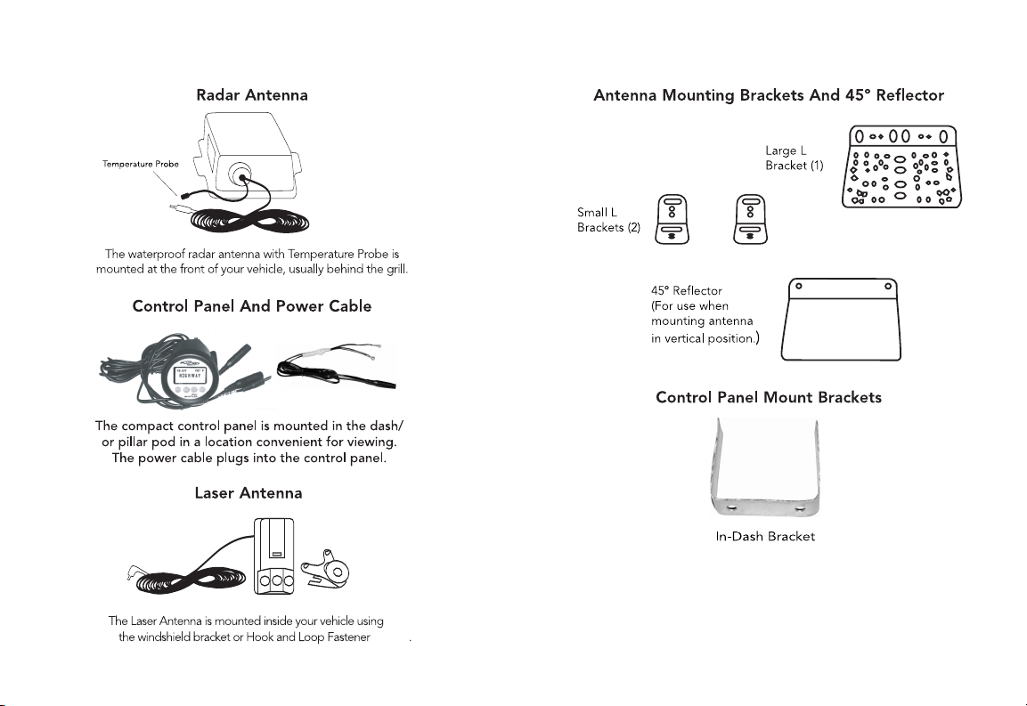
WHISTLER FUZION COMPONENTS
MOUNTING BRACKETS
INTRODUCTION
3
4
Page 4

MOUNTING FASTENERS
Bolt
#10-32 x 1-1/4"
Bolt
#10-32 x 1/2"
Nut
4mm
Lock Washer
4mm
Flat
Washer
A
B
Sheet metal
Screw
#6 x 3/4"
Sheet metal
Screw
#4 x 5/8"
Hook and
Loop Fastener
C
D
E
F
G
H
J
I
Mountable
Cable Tie
4" Cable Tie
K
Interface Cable
Nut
5mm
Lock Washer
5mm
L
M
MOUNTING FASTENERS
Reference Description/Use Qty
A Bolt #10-32 x 1-1/4" 2
5
B Bolt #10-32 x 1/2" 2
C Nut #10-32 4
D Lock Washer 4
E Flat Washer 2
F Sheetmetal Screw #6 x 3/4" 7
G Sheetmetal Screw #4 x 5/8" 2
H Hook & Loop 1/2” x 1” 1
I Mounting Cable Tie 1
J 4" Cable Tie 5
K Interface Cable 1
L
M
Note: If mounting fasteners are missing from your package,
please call 1-800-531-0004 for replacements.
• Fastens Large L or Small L
Bracket to vehicle support.
• Fastens Small L to Large L
Bracket (optional approach).
• Use with #10-32 bolts.
• Use with #10-32 bolts.
• Use with #10-32 bolts.
• Fastens Large L/Small L Bracket
or 45° Reflector to radar antenna.
Mounts Temp. Probe
• Fastens hanging bracket
to interior vehicle surface.
• Fastens LRM-5 to back
earview mirror when
of r
windshield bracket is not used.
om radar
es cable fr
• Secur
antenna at various locations
in engine compartment.
om radar
es cable fr
• Secur
antenna at various locations in
or under the vehicle.
• Connects the radar antenna
to inside contr
Nut 5mm
• Used with studs on control
panel
Lock W
• Used with studs on contr
panel
ol panel
asher 5mm
ol
6
2
2
Page 5

INSTALLATION OF RADAR ANTENNA
General Information
The radar antenna is waterproof and designed to be mounted
at the front of your vehicle. In most vehicles the best mounting
location is directly below or behind the bumper. Radar signals
will pass through non-metallic materials such as fiberglass and
plastic, however, be sure to mount the receiver away from any
metal, as it will block the receiver’s antenna. Because the optimal
location for mounting the antenna varies by vehicle type, the
hardware supplied is designed to offer a wide variety of mounting
options. We suggest choosing the option that enables the
antenna to be securely fastened and provides the antenna
window adequate rearward visibility.
NOTE: The “antenna” is the bubble area on the case. All
references to antenna in this manual will be the bubble area.
NOTE: Use of hardware that is not supplied or DRILLING
into the case will cause damage to the receiver and void the warranty.
Antenna Mounting Brackets
There are two types of mounting brackets for the antenna:
Large L (1) and Small L (2). The Large L bracket fastens to the
through the hole on the flange of the antenna and then
tighten into the metal bracket (do not over tighten). The
Large L Bracket may be fastened to the antenna in a variety of
positions as shown on page 8.
INSTALLATION OF RADAR ANTENNA
This arrangement provides flexibility for fastening the
antenna/bracket assembly to your vehicle in a manner that
allows the antenna window (ANTENNA) to have a forward
looking view of the road ahead.
The Small L Brackets (2) may also be fastened to the antenna in
different positions as shown below:
Use one #6 x 3/4" screw to fasten each Small L Bracket to the
antenna. Again, do not over tighten the screws.
Do not drill into the receiver housing!
7
In some situations it may be advantageous to use both the
Large Land Small L Brackets to install the antenna in a vehicle.
8
Page 6

INSTALLATION OF RADAR ANTENNA
The Small L Brackets are fastened to the Large L Bracket using
the #10-32 x 1/2" bolts, #10-32 nuts and lock washers.
To fasten the Large L or Small L Brackets to your vehicle, mark
the supporting structure through the appropriate holes in the
brackets, then drill the holes in the supporting structure with a
13/64" drill bit. Attach the bracket(s) to the supporting
structure using two bolts (#10-32 x 1-1/4") and corresponding
nuts, flat washers, and lock washers. You may also use 2 #6
sheet metal screws. Because rough road surfaces can cause
excessive vibration or bouncing, be certain to fasten the
bracket(s) securely to your vehicle.
Horizontal Or Vertical Mounting Of Antenna
The antenna can be attached to the vehicle in a horizontal or
vertical position, or at any angle between these two points.
Select the position that allows you to fasten the antenna to
your vehicle in the most secure manner
9
INSTALLATION OF RADAR ANTENNA
Horizontal Mounting
When mounting the antenna in a horizontal position (or on an
angle between), remember to keep the ANTENNA window as
close to perpendicular as possible to the road surface
(ANTENNA window should not be angled up toward the sky or
down toward the road surface).
Mounting Vertical (with 45º Reflector)
For vehicles that do not have sufficient clearance behind the
bumper (about 5") to mount the antenna in a horizontal
position, the 45º. Reflector should be used.
The 45º Reflector is attached to the antenna with two screws (#6
x 3/4") on the side of the antenna housing marked ANTENNA.
Slide the screws through the corner holes on the flange of the
antenna housing and then tighten into the metal reflector (do
not over tighten).
10
Page 7

INSTALLATION OF LASER ANTENNAINSTALLATION OF RADAR ANTENNA
Mount the antenna to the vehicle such that the ANTENNA
window is facing the road surface, sky, right or left of the
vehicle, and the reflector has an unobstructed view of the
road ahead.
Mounted in this position, radar signals are reflected into the
ANTENNA window.
Mounting the Temperature Probe
Find a location that is far enough away from the engine and
radiator heat but still in the airflow for the vehicle. Mounting
the Probe too close to these heat areas will give a false high
temperature.
• Attach the mountable tie wrap (supplied) to the
Temperature Probe as shown.
• Mark location for Probe, then drill a hole using a 7/64” drill
bit. Attach Probe with tie wrap in the correct orientation
using the #6 x 3/4 screws.
NOTE: Mount the Probe so that there is space between the
Probe and the mounting area.
Do not
mount Probe directly to metal area.
Antenna Cable to the Control Panel
Once the antenna is installed connect the cable from the
radar antenna to quick disconnect interface cable. Tie this
cable in knot similar to using an electrical extension cord.
Run the cable along the edge of the engine compartment to
the firewall. Find a location in the firewall where other wires
(or the speedometer cable) enter the passenger compartment
and feed the stereo jack connection through. Be careful not
to interfere with or disconnect other wires, cables, or mechanical
systems of your vehicle while routing the antenna cable. Also,
keep the antenna cable away from any areas in the engine
compartment that may become hot. Cable ties are provided
to secure the antenna and Temperature Probe cables at
various points in the engine compartment.
General Laser Information
The laser antenna provides both front and rear laser reception.
Mount the laser antenna with the 3-lens array facing forward
(down the road) and the single lens facing behind. This approach
offers the greatest protection, since you will most often be
traveling into a laser signal, rather that away from it when laser
speed enforcement is encountered. For effective protection,
make sure the laser antenna has an unobstructed view forward
and behind, and that it is not placed behind metallic sun screens.
Mounting the Laser Antenna
The laser antenna can be mounted to the front windshield
using the windshield bracket supplied.
11
12
Page 8

INSTALLATION OF LASER ANTENNA INSTALLATION OF CONTROL PANEL
Installing the Laser Antenna
Before using, attach the suction cup and rubber bumpers (2)
to the metal bracket. If necessary, you may bend the metal
bracket in order to position the laser antenna correctly (3-lens
array facing forward, single lens facing behind.)
Laser antenna mounted with windshield bracket.
Using Hook & Loop Fasteners, the laser antenna may also be
mounted to the back side of your rearview mirror. Be careful not
to block the rear facing lens when mounted in this manner.
Also, clean the appropriate surfaces with isopropyl alcohol before
adhering the adhesive side of the fastener to those surfaces.
The Fuzion remote is designed to fit into standard 2 1/16”
gauge housings. This unit is perfect to complement other
gauges in a pillar pod or install in its own gauge housing.
Since the control panel dimensions are the same as standard
automotive gauges, the aftermarket offers many enclosures
that can customize the installation
Depending on the housing, the Fuzion control panel may
either be tight or loose fitting. If loose, we provide a special
“U” shaped bracket that will hold the control panel tightly to
the housing. This same bracket can be used when flush
mounting the control panel to a location in the vehicle’s dash
or installation in an under dash kit.
The “U” bracket is held in place using the supplied 5mm nuts
and washers. DO NOT remove the nuts already installed on
the control panel.
If the unit is installed into a pillar housing, see the pillar
housing instructions (if any) for proper installation for that
housing.
Laser antenna mounted to rearview mirror with Hook & Loop Fasteners.
13
14
Page 9

INSTALLATION OF CONTROL PANEL
PWR - 12 Volt Connection
AUX - LED, Tone Voice Module Output
LAS - Laser Module Input
ANT - Radar Receiver Input
2. Auxiliary Port
1. Power Port
3. Laser Port
4. Antenna Port
INSTALLATION OF CONTROL PANEL
Antenna Cable Connection
The stereo connector on the end of the antenna cable plugs
into ANT. cable on the back of the control panel.
Laser Antenna Cable Connection
After mounting the laser antenna conceal the cable and plug
the stereo jack connector into the labeled
Power Cable Connection
The power cable has a plug on one end which connects to the
cable labeled PWR. At the other end of the power cable the
power and ground wires are separated. The ground wire has a
“U” type connector which should be fastened to a metal
surface. Look for an existing screw or bolt under the dash to use
as a grounding point. The power wire has a spade type connector
which should be connected to a switched +12 volt DC circuit in
your vehicle’s fuse box. A switched circuit is one that has power
when your vehicle is on, but has no power when your vehicle is
off. Connect the “U” type connector to the ground point
selected, attach the power cord plug to the control panel cable
marked “PWR” then touch the power wire to the +12 volt DC
switched power source selected; if the control panel begins the
self test sequence, then all connections are correct.
LAS Cable.
15
16
Page 10

INSTALLATION OF VOICE MODULE
TROUBLESHOOTING
The Voice Module provides not only remote audio but voice
announcements as well.
To install:
• Make sure the external speaker option is turned on (factory)
default setting is voice on, if not see option mode in owners
manual
• For maximum volume, find a convenient location close to
the driver’s ear, such as the trim panel between A & B pillars.
Attach speaker using the supplied clip or velcro.
• Plug the cable into the aux cable on the detector. Run this
cable conveniently from the detector to the location selected,
so that it doesn’t interfere with normal driving operation.
NOTE: This module has its own independent volume control.
PROBLEM: No display or audio.
• Check fuse in power cable, replace if necessary.
• Check fuse in fuse box, replace if necessary.
• Make sure power cable is properly grounded.
PROBLEM: Unit alarms when using vehicle equipment or
electrical accessories (brakes, power mirrors/windows,
directionals, horn, etc.)
• Check condition of vehicle’s electrical system, including
battery and alternator.
• Install a filter capacitor (470mfd. 25 volt or larger
capacitor value) where power connection is made.
PROBLEM: Audio alerts are not loud enough.
• Cancel Auto Quiet Mode or City Mode
• Check audio level settings.
PROBLEM: Display shows R error.
• Warning communicates “loss of link” between
control panel and front antenna (RADAR).
• Check antenna connection at back of control panel.
• Contact factory, if you suspect antenna is defective.
• Look for cuts in the cable
If difficulties occur which cannot be solved by information in this
Troubleshooting Guide, please call Whistler Customer Service at
1-800-531-0004 or visit our FAQ page at www.whistlergroup.com,
before returning your unit for service.
For warranty information, refer to owner’s manual.
17 18
 Loading...