

Page 1

OWNER’S MANUAL
XTR-690/695
Total Band Protection
™
LASER-RADAR
DETECTOR
The Whistler Group Corporate Headquarters
3604 NW Frontage Rd. • Bentonville, AR 72712
Tel 479.273.6012 • Fax 479.273.2927
Customer Return Center
551 N. 13th St. • Rogers, AR 72756
Customer Service Tel 800.531.0004
www.whistlergroup.com
One or mor
#5,146,227, #5,379,456, #5,666,120,
P/N 260013, Rev 1 ©2009 The Whistler Group, Inc.
e U.S. patents may apply:
#5,990,821, #7,215,276
Dear Whistler Owner,
If you have questions concerning the operation of this
Whistler product please call:
CCuussttoommeerr SSeerrvviicce
11--880000--553311--0000004
e
4
Monday - Friday • 8:00 am - 5:00 pm CT
or visit our website
www.whistlergroup.com
Please keep the receipt in a safe place. You may
register your product online
For warranty
verification purposes, a copy of your dated
at www
..wwhhiissttlleerrggrroouupp.
.
com.
store receipt must still accompany any unit sent in for
warranty work. If the unit is returned without a dated store
receipt, an out of warranty service charge applies.
YYoouurr wwaarrrraannttyy ppeerriioodd bbeeggiinnss aatt tthhee ttiimmee ooff ppuurrcchhaassee.
TThhee wwaarrrraannttyy iiss vvaalliiddaatteedd oonnllyy bbyy tthhee ddaatteedd ssttoorre
rreecceeiipptt!!
Please record the serial number of the unit in
NNoottee:
:
.
e
the space provided in the warranty section of the
manual.
To fully acquaint yourself with the operation of your
Whistler detector and to better understand the
differences between detecting radar, laser, and
safety radar signals, we recommend reading this
entire manual or visiting our F.A.Q. page on our
website www.
wwhhiissttlleerrggrroouup
p
.com
Enjoy your Whistler detector and please drive safely.
Sincerely,
The Whistler Group, Inc.
Model Features Summary . . . . . . . . . . . . . . . .3 - 4
Installation . . . . . . . . . . . . . . . . . . . . . . . . . . .5 - 6
•
Mounting Guidelines
•
Windshield Mounting
•
Power Connection and Fuse Replacement
Operation . . . . . . . . . . . . . . . . . . . . . . . . . . .7 - 16
•
P
ower On, Self Test
•
Teach/Tutorial Mode
•
Setting Saver
• Feature Engaged Confirmation 7
• Integrated Real Voice
• Audio Level Adjustment 8
• Auto Quiet Mode 8
• Quiet Mode 8
• External Audio Jack (XTR-695 only) 8
• City/City 1/ City 2 Mode 9
• Highway Mode 9
• Vehicle Battery Monitor 9
• Twin Alert Periscopes 10
• C
ompass Mode
• B
acklight Setting
• 7
Color Multi-band Display
• Vehicle Battery Saver Mode 11
• Filter Mode 12
• O
ption Select Mode
• S
Alert Feature 14
tay
Safety Warning System
• Alert Priority 15
• Compass Calibration Set-up 15
• Reset Features 16
• Intellicord
Ka RSID (XTR-695 only) . . . . . . . . . . . . . . . . . . . .17
(XTR-695 only) . . . . . . . . . . . . . . . . . . . . . .17
LSID
POP™Mode Alerts . . . . . . . . . . . . . . . . . . . . . .18
Laser/Radar Alerts . . . . . . . . . . . . . . . . . . . . . .18
• Speed Radar Audio/Visual Alerts 18
• Laser Audio/V
• Pulse Protection
Troubleshooting Guide . . . . . . . . . . . . . . . . . . .19
Care and Maintenance . . . . . . . . . . . . . . . . . . .20
Are Detectors Legal? . . . . . . . . . . . . . . . . . . . .20
FCC Information . . . . . . . . . . . . . . . . . . . . . . . .20
Speed Monitoring . . . . . . . . . . . . . . . . . . . .21 - 23
• POP™Mode 21
• Laser Facts 21 - 22
• Radar Facts 22
• Other Speed Detection Systems 22 - 23
• Radar Detector Detector 23
Warranty Information . . . . . . . . . . . . . . . . .23 - 26
Specifications . . . . . . . . . . . . . . . . . . . . . . . . . .26
Accessories . . . . . . . . . . . . . . . . . . . . . . . . . . . .27
®
®
™
. . . . . . . . . . . . . . . . .14
isual Alerts
®
(XTR-695 only) 11
5
6
6
7
7
7
7
10
10
13
16
18
18
Page 2
WHISTLER FEATURES
Feature Listings of XTR-690/695
1
6
9
0
1
8
12
4
13
3
2
11
7
3
5
4
5
1
6
9
10
8
12a
13
2
11
7
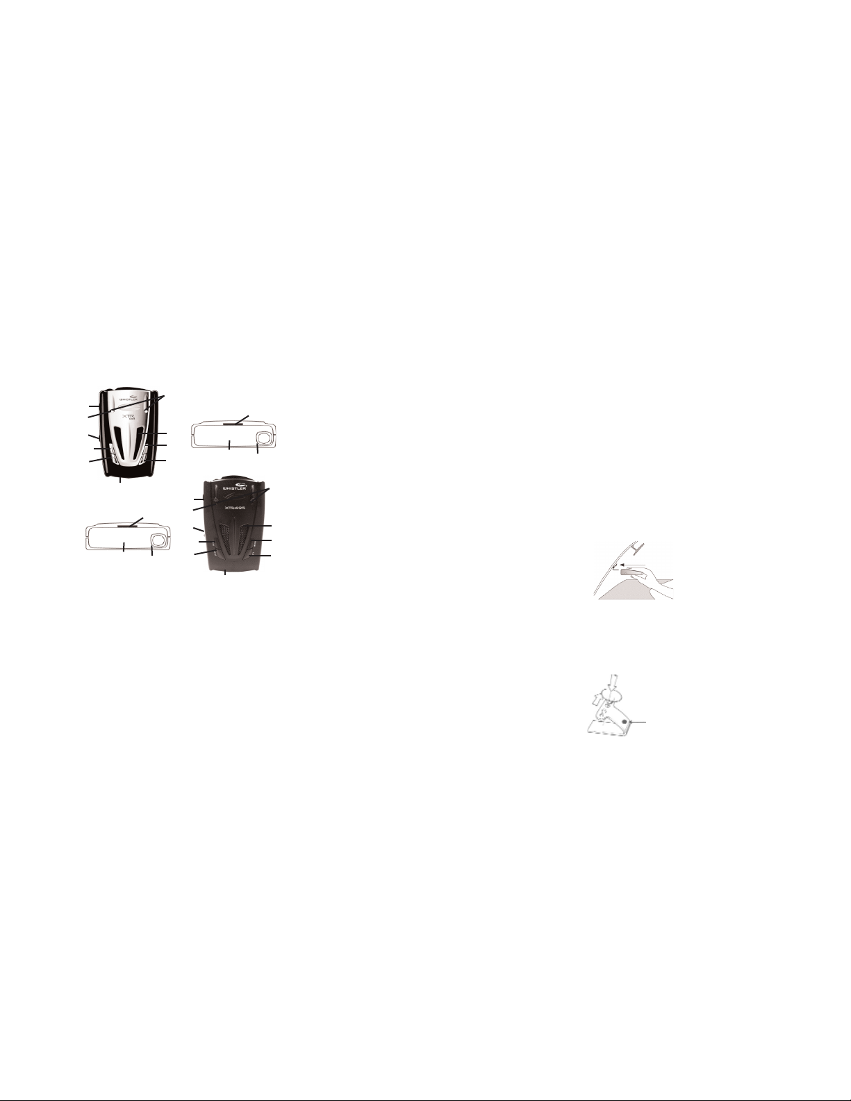
FEATURE DESCRIPTIONS
Whistler’s ergonomic and user-friendly design
provides a new level of operating convenience.
Special features include:
1. Bracket Release Button – provides quick
and easy release of the mounting bracket.
2. Speaker – provides distinct audio warnings
for X, K, Ka band radar, safety radar, and laser
Mounting Bracket Location
3.
mounting bracket firmly.
4. Radar Antenna – compact, high-efficiency
antenna r
eceives radar signals.
– slot holds
3
FEATURE DESCRIPTIONS
5. Front Laser – high gain optical lens
rovides increased sensitivity and field of
p
iew for leading-edge laser detection.
v
6. Rear Laser – an integrated optical
aveguide provides superior detection of
w
aser signals transmitted from behind.
l
7. City Button - reduces the annoyance of
false alerts typically encountered in urban
riving areas.
d
8. Quiet Button - pressing QUIET before a
signal is detected engages Auto Quiet Mode
tomatically reduces the audio level after
hich au
w
the initial warning to a low audio level setting.
Pressing QUIET during a radar/laser encounter
silences audio alerts, while allowing visual
alerts to keep you informed.
9. Power / Volume Control – push this button
to turn the unit on/off. Move back or
forward to adjust the audio level.
10. Dim / Dark - engages Dim/Dark modes.
11. Menu Button - enters Option Select Mode.
12. Blue Backlit LCD Text Display – provides
distinct visual confirmation of si gnals
detected, signal strength, and indicates
engaged modes of operation.
12a.7 Color Backlit LCD Text Display –
provides distinct visual confirmation of signals
detected, signal strength, and indicates
engaged modes of operation in 7 colors.
13. Twin Alert Periscopes - provide an
additional attention getting visual aler
IMPORTANT:
.
ttoo pprroovviiddee aaccccuurraattee ccoommppaassss hheeaaddiinnggss..
SSeeee CCoommppaassss CCaalliibbrraattiioonn SSeett--uupp sseeccttiioonn
oonn ppaaggee 1155..
TThhee uunniitt mmuusstt bbee ccaalliibbrraatteedd
45
Mounting Guidelines
INSTALLATION
Mount the unit as low as possible near the
•
enter of the windshield.
c
• Do not mount the unit behind wipers,
rnaments, mirrored sunscreens, etc. These
o
obstructions have metal surfaces which can
ffect radar and laser signals and reduce
a
ritical warning time. (Regular tinted glass
c
does not affect reception).
• Some windshields have an Instaclear
E
signals. Consult your dealer or the owner’s
manual supplied with your vehicle to determine
if your windshield has this coating.
• Avoid placing the unit in direct contact with
the windshield.
• To reduce the possibility of theft, conceal
the unit when not in use.
Windshield Mounting
• Install the two suction cups and rubber bumper
onto the bracket by fitting them into their holes.
t.
• Pr
location you have chosen.
™
lectriclear
IIMMPPOORRTTAANNT
ess the suction cups onto the windshield at the
ype coating, which affect radar
t
T
: Make sure the unit is level
Rubber
Bumper
™
r
o
Windshield
Mounting
Page 3

Important: Some newer cars have a plastic safety
INSTALLATION OPERATION
oating on the inside of the windshield. The
c
indshield bracket may leave permanent marks on
w
this type of surface. To find out if your vehicle has
his type of windshield, check the vehicle’s owner’s
t
anual or ask your dealer. We recommend that you
m
do not leave the suction cup bracket on the window
in direct sunlight. If the detector is removed, this
ay cause blistering of the dash in some
m
vehicles.
• Slide the detector onto the bracket until it locks into
lace.
p
• If necessary, the unit may be leveled by bending
the windshield bracket. Press the bracket release
button and remove the detector before bending.
Power Cord Connection
• Plug the small end of the power cord into the
unit’s power jack.
• Plug the large end into the vehicle’s cigarette
lighter socket.
:
NNoottee:
Cord fits tightly into detector. When
installing the cord, expect some resistance.
Fuse Replacement
The lighter socket plug is equipped with a
replaceable 2 amp, 3AG fuse located behind the
silver tip. To replace the fuse, carefully unscrew
the tip of the plug.
IImmppoorrttaanntt:
spring which may fly out when disassembling.
Insert the new fuse with the spring and screw on
the tip. With use, screw cap on plug may loosen.
Retighten occasionally.
:
Unscrew slowly. The tip contains a
Power On, Self T
To turn the unit ON or OFF, push the center of
the Power/Volume button.
Each time your Whistler detector is turned on,
an automatic self-test sequence confirms that
the speaker and visual displays are functional.
Display shows in order:
•
1. WHISTLER 2. X-band 3. K-band 4. Ka-band
5. LASER ON 6
OP ON9.BSVR ON 10.FILTER 11.COMBO
8.P
12. HIGHWAY
Teach/Tutorial Mode
Provides simulated alerts for each type of signal.
• Press City and Quiet buttons simultaneously
• Display Shows:
• Press Dark button to exit.
Setting Saver
Setting Saver saves your personalized settings
so that when the detector is turned off and then
on again, you do not have to re-enter them.
Feature Engaged Confirmation
Each time a button is pressed, one beep confirms
feature “on”, two beeps confirm feature “off”.
Integrated Real Voice
When selected, Real Voice®will be used to
articulate the following:
Band Identification
1.
2. Safety Warning System messages
Feature Selection
3.
Note: In certain cases, the voice message does not
replicate the text message.
est
..
SR OFF 7. VOICE ON
®
Audio Level Adjustment
OPERATION
T
o change the audio level:
•
Move Power/Volume button back to increase
audio level.
• Move Power/Volume button forward to
d
ecrease audio level. As audio level is
adjusted, beeps are provided and the display
indicates volume level.
Auto Quiet Mode
Auto Quiet mode re
to level (1) approximately 5 seconds after a radar or
safety radar signal is detected. The alert
new signal within 20 seconds will re
Auto Quiet mode does not affect laser alerts.
• Press Quiet (before a signal is detected) to
engage Auto Quiet.
• Once the Auto Quiet mode is engaged, you
may cancel the audio alarm by pr
• Press Quiet (when the unit is not alarming) to
cancel Auto Quiet mode.
Quiet Mode
Quiet mode cancels audio during an alert and any
new alert within 20 seconds. After 20 seconds of no
radar signal detected, on the XTR-690, 2 beeps are
ovided on any new aler
pr
remains quiet; on the XTR-695 the audio alerts are
restored.
• Press Quiet to cancel the audio.
• Press Quiet a second time during an alert to
restore the standard audio alert pattern; or turn
the unit off, then on.
External Audio Jack (XTR-695 only)
The 2.5mm external audio jack can be used to
connect an exter
onments with high ambient noise levels. The
envir
internal speaker will be disconnected.
duces the selected audio level
for any
sume at level (1).
essing Quiet.
t and then the audio
nal speaker or headphones in
6
7
8
Page 4

City/City 1/City 2 Mode
OPERATION
W
histler’s Three Stage City Mode is designed to
reduce the annoyance of automatic door openers,
i
ntrusion alarms and other devices which share frequencies
w
ith police radar. Generally, X band is used for these
devices.
• Press City button to cancel Highway Mode
and engage City Mode.
• Press City button again to enter City 1 Mode.
• Press City button again to enter City 2 Mode.
• Press City button a fourth time to cancel City 2
Mode and returns the unit to Highway Mode.
In City Mode, weak speed/safety radar signals give
an initial alarm of two beeps, and then remains
quiet unless the signal becomes very stro
the signal strength increases, two additional beeps
are provided. City 1 and City 2 Modes operate the
same as Highway Mode, but in City 1 Mode, only the
X band sensitivity is lowered. In City 2 Mode, X-band
is not detected.
Caution: Some towns/small cities may still be using X
band radar. City Modes do not change the audio alert
.
for laser
Highway Mode
Highway mode provides full audio warnings any
time radar (X, K, Ka, Safety Radar) or laser signals
are detected, and is recommended for open road
driving.
Note: In Combo Mode, an “
indicate mode of operation.
For more information on City and Highway modes, please visit
our F.A.Q. page on our website: www
Vehicle Battery Monitor
The vehicle’s battery voltage can be displayed
by pressing and holding the Dark and Quiet
buttons simulatneously. Pressing Dark and Quiet
simultaneously again will exit the batter
monitor.
H
H
” or “
.whistlergroup.com
9
ng. When
C
C
” will be shown to
y
Twin Alert Periscopes
OPERATION
Whistler’s new Twin Alert Periscopes provide an added
attention getting visual alert. The two extra LEDs flash on
and off when the unit alarms to provide a unique visual alert.
This alert can be programmed, through the Option Select
Mode to: 1. flash for all alarms, 2. remain on, or 3. turn LEDs
off completely.
Compass Mode
The unit is programmed from the factory in “Combo
COMBO mode means that the unit provides
Mode”.
both compass headings as well as detects laser/radar
signals. Through the “Option Select Mode”, either
laser/radar or compass features can be turned off;
RADAR equals detection of all police bands and laser;
COMPASS equals no detection of police laser/radar.
Note: The unit must be calibrated to provide accurate
compass headings. See Compass Calibration Set-up
section on page 15.
Backlight Setting
The backlighting can be programmed to be illuminated
all the time, only when alarming, or various other
combinations. The options are selectable by pressing the
Dark button on the unit. The first condition is during
normal operation and the second is when the unit alarms.
The options are:
Normal - Alarm
OFF - OFF
OFF - DIM
OFF - BRT
DIM - OFF
DIM - DIM (XTR-695 only)
DIM - BRT
BRT - BRT
10
Backlight Setting (continued)
OPERATION
Backlight will turn on, if selected, while the unit
alarms and remain on for 3 seconds after the unit
tops alarming. When any button is pressed, the
s
backlight will illuminate at the dim setting and
remain on for 3 seconds afterwards. The
acklight will also illuminate while in option
b
mode.
7 Color Multi-band Display
XTR-695 only)
(
he display can be set so that each Band alert
T
can be a different color (i.e. K Band alerts in
Blue, X Band alerts in Green, Ka Band alerts in
Purple, etc,) or Scroll ALL colors while alarming.
To make changes see Option Select Mode steps
17 thru 20 on page 13.
Vehicle Battery Saver Mode
The Vehicle Battery Saver Mode automatically shuts
off the detector after 3 hours. The timer is reset if
the detector is turned off, unplugged or any button
is pressed before the timer has expired. The
detector will alert you with an audible and visual
warning before it shuts off. During this warning, you
can momentarily reset the timer by pressing any
button. If the unit has automatically turned off, press
any button to turn the unit back on.
“Option Select Mode” for instructions for
changing the battery saver mode options.
11
Refer to
Page 5

Filter Mode
OPERATION
There are times when a radar detector in another
ehicle, can unintentionally emit a frequency
v
which can cause your detector to falsely alarm.
The Whistler Filter Mode options provide
dditional signal processing to minimize the
a
occurrences of these false alarms. Filter mode
vides normal pro
pro
odes provide additional signal analysis before
m
ing.
alarm
ilter Mode is the factory default setting and
F
should provide adequate filtering for most
conditions. If you experience excessive alerts
due to radar detectors in other vehicles, try Filter
1, then Filter 2 modes. Filter Mode analysis
occurs in Highway Mode and all City Modes. See
Option Selection Mode to change the filter
settings.
cessing. Filter 1 and Filter 2
12 13 14
OPERATION
Option Select Mode
ess the Menu button to enter Option Select Mode.
Pr
hen selecting options, the Dark or Quiet buttons must
W
e pressed within 20 seconds or Option Select Mode will
b
automatically exit. T
Press the Power button to exit Option Select Mode.
o enter:
OPERATION
Stay Alert Feature
T
he Stay Alert Feature is designed to test a driver’s
a
lertness. To engage (when the unit is not alarming) :
•
Press and hold the City button for
a
pproximately 2 seconds. Release the button
during or immediately after the alert is given.
Display shows:
Within 30-60 seconds, two beeps are
t
o show alertness, the driver must press either the
City, Menu, or Quiet buttons within 3-5 seconds. If a
button i
s pressed within 3-5 seconds, the cycle is
repeated.
If a button is not pressed within 3-5 seconds, an
alarm sounds and the display shows:
• Press the Dark button to exit the Stay Alert feature.
WARNING!!! Stay Alert is NOT intended as a
substitute for adequate rest. You should NOT
operate a vehicle if you are drowsy. During
extended periods of vehicle operation, you should
take frequent breaks. Improper reliance on the Stay
Alert feature may result in vehicle damage,
personal injury or death.
VEHICLE IF YOU ARE DROWSY.
Safety Warning System™
In communities where transmitters are located,
the Safety Warning System™displays over 60
text messages. When Safety Radar is detected
the audio alert is geiger counter-like.
Safety Warning System Text Message
Example: Poor - Road - Surface.
Note: Not all areas have Safety Warning System
transmitters.
NEVER OPERATE A
™
SWS
sounded;
™
Page 6

OPERATION
t Priority
Aler
hen two or more signals are received at the
W
ame time, the alert priority is:
s
1. Laser 2. Speed Radar 3. Safety Radar
Example: If X band is alerting, then suddenly a
aser signal is detected, the laser warning will
l
verride the X band alert.
o
Compass Calibration Set-up
he unit will need to be calibrated in order for
T
the compass to provide accurate headings. To
calibrate the unit, perf
procedure:
.
11.
Mount the unit level in the center of the
vehicle’s windshield. Make sure there are no
magnetic sources near the detector
(i.e., speaker)
2
2
. Select a large clear area
without any power lines.
3
3
. Press the Menu button until display shows
CCAALL MMOODDE
simultaneously. The display shows (scrolling):
4
4
the Dark and Quiet buttons simultaneously to
complete calibration. The unit will beep twice and
display shows, for example:
Note: In Combo Mode, an “
shown to indicate mode of operation.
Important: If unit mounting is relocated in the
vehicle, (i.e., visor to windshield mounting or
dash mounting), or if the unit is moved to
another vehicle, you must recalibrate the
compass.
E
. Then press the Dark and Quiet buttons
. If calibration does not automatically finish press
.
orm the following
(parking lot or field)
H
C
H
C
” or “
15
” will be
OPERATION
Reset Featur
ll user features can be reset to factory settings.
A
Unplug the Power Cord from the unit.
•
Press and hold the Power and Quiet buttons.
•
•Plug the Power Cord into the unit.
•Wait for 2 beeps.
•Release the Power and Quiet buttons.
Unit is now reset to the following features
and settings.
efault factory settings are:
D
1. S1: (For Intellicord®) Power ON or OFF.
2. S2: (For Intellicord®) Quiet feature.
3. Combo Mode.
4. HIGHWAY Mode.
5. Dim/Dark Mode to full illumination of display.
6.A
uto Quiet Mode OFF
7. Safety Radar OFF.
8. Vehicle Battery Saver ON/3hrs.
9. Full Power Up sequence.
10. Default TONE 3.
11. All Bands ON.
12. Laser ON.
13. POP ON.
14. Voice ON.
LED Periscopes to BLNK.
15.
16. Filter Mode.
Intellicord® Ready
Using Whistler’s optional Intellicord®Power Cable
allows some models to control the detector’s
features such as Power On/Off, City Modes,
Dim/Dark, and Quiet/Auto Quiet with a simple
ess of the button on the Power Cable. Two
pr
features can be controlled: one by a short press of
the button, and the second by a long press of the
button. Option Mode allows the user to program
the feature assignments.
es
.
16
OPERATION
((XXTTRR--669955 oonnllyy)
that will assist the driving enthusiast to further
i
dentify threats from laser and Ka band radar guns.
Ka RSID (Ka Radar Signal IDentifier)
I
dentify the difference between the likelihood of a Ka
t
hreat vs. the likelihood of a Ka false from another
source (possible radar detector). The Ka RSID
f
eature will educate you to the common Ka speed
radar guns by displaying the nominal police radar
fre
quencies of 33.8GHz / 34.0GHz / 34.3GHz /
34.7GHz / 35.5GHz. The Ka alerts that do not fall into
the common Ka speed radar windows will be re
only as Ka.
Note: This product is not a fre
XTR-695 will categorize the received Ka signal and
select the appropriate information. Treat every Ka
alert with caution.
LSID (Laser Signal IDentifier)
Identify the Laser gun’
Second) that is transmitted by the speed laser gun.
LSID may also be used to identify other forms of laser
sources such as LACC (Laser Assisted Cruise Control)
systems found in some high end vehicles.
If the Laser PPS information displayed is due to
another source such as local airports or LACC, LSID
allows you to Lock Out this rate fr
continuous audio alert during this and any new
encounter of the same rate. To Lock Out a PPS, press
the Quiet button during the Laser aler
place an
Lock Out this signature ID. Any new encounter with
the same Laser Signatur
information and two quick beeps.
Note: Common Laser PPS rates used in the USA are
100 / 125 / 130 / 200 / 238 / 380Hz. Other Laser PPS
rates used outside the USA include 600Hz.
Caution: Do not lock out a PPS rate if it is close to
known speed laser guns.
)
Whistler has two new exciting features
ted
por
quency counter
s pulse rate or PPS (Pulses Per
om giving you the
* on the screen beside the PPS rate and
e ID will pr
ovide the display
. Yo
t. This will
17
ur
Page 7

POP™ MODE ALERTS
POP™Mode Alerts
ecause POP
B
K or Ka band frequencies, POP
displayed as regular radar alerts.
™
ode radar utilizes the same
M
™
Mode Alerts will be
LASER/RADAR ALERTS
Speed Radar Audio/Visual Alerts
When X, K or Ka is detected, the band ID and
ignal strength are
s
continuous and has a geiger counter-like
pattern. The faster the beep, the closer or
tronger the radar sourc
s
Laser Audio/Visual Alerts
When a laser signal is detected the audio alert is
continuous for a minimum of 3 seconds.
• The Displays Shows:
Pulse Protection
Pulse (or instant-on) radar is more difficult to
detect than conventional radar because it
remains ‘off’ until activated to measure the speed
of a targeted vehicle.
When a pulse type transmission is detected, your
Whistler detector sounds an urgent 3-second
audio warning and the display shows:
After the 3-second pulse alert, the standard alert
pattern continues for as long as the signal is
present.
It is important to r
alert, since warning time may be minimal.
displayed. The audio alert is
e.
®
espond pr
omptly to a pulse
18
TROUBLESHOOTING
our Whistler detector is expertly engineered
Y
nd designed to exacting quality standards to
a
provide you with reliable, trouble-free operation.
f your unit has been correctly installed following
I
he guidelines in this manual, but is not
t
operating optimally, please refer to the
roubleshooting guide below.
t
PROBLEM: No display or audio.
• Check fuse in plug; replace if necessary with a
2 amp, 3AG type.
• Check fuse for lighter socket; replace if
necessary.
• Make sure lighter socket is clean.
PROBLEM: Unit alarms when vehicle hits
bumps.
• Check for loose lighter socket; tighten and
clean.
• Check connections at both ends of the power
cord. Substitute another cord to determine if
the cord is defective. Return defective cord to
the factory.
PROBLEM: Audio alerts are not loud
enough.
• Cancel Auto Quiet Mode or City Mode.
• Check audio level setting
If difficulties occur which cannot be solved by
information in this Troubleshooting Guide, please
call Whistler Customer Service at 1-800-531-0004
or visit our F.A.Q. page at
whistlergroup.com/faq-detectors.asp,
www.
before returning your unit for service.
(see page 8 ).
19
CARE AND MAINTENANCE
uring the summer months, avoid prolonged
D
xposure to direct sunlight by removing your unit
e
from the dash when your vehicle is parked for an
xtended period of time. Do not spray water,
e
leaners, or polishes directly onto the unit. The
c
spray may penetrate through the openings and
amage the unit. Also, do not use any abrasive
d
cleaners on the unit’s exterior.
ARE DETECTORS LEGAL?
In Most States YES.
Laser-Radar detectors are legal in every state
(except Virginia and Washington, D.C., which have
local regulations restricting the use of radar
receivers in any vehicle) when used in
automobiles or light trucks (under 10,000 lbs.).
The Federal Highway Administration (FHWA)
issued a regulation, effective January, 1994 which
prohibits radar and laser detector use in vehicles
over 10,000 lbs. Prior to the FHWA regulation,
laws existed in New York restricting the use of radar
detectors in trucks over 18,000 lbs. and in Illinois in
trucks over 26,000 lbs.
FCC INFORMATION
FCC ID: HSXWH20
This device complies with par
Operation is subject to the following two conditions:
(1) This device many not cause harmful interference,
(2) this device must accept any interference received,
including interference that may cause undesired operation.
Important: FCC requirements state that changes or
modifications
void the user’s authority to operate the equipment.
not expr
t 15 of the FCC Rules.
oved by Whistler could
essly appr
20
Page 8

SPEED MONITORING
POP™ Mode
POP™Mode is a featur
operating on K and Ka bands. When the gun
guns
is in POP™Mode and activated, a brief burst of
gy, less that 1/15 of a second, is transmitted
ener
vehicle’s speed is quickly acquired. A
and the
detector without P
cannot respond to this brief transmission.
Laser Facts
It’s well documented that many radar guns
cannot reliably provide the speed of a targeted
vehicle that is traveling in a group of vehicles. In
contrast, a laser gun can target a specific vehicle
out of a line of traffic and determine its speed. The
advantage of laser over radar in terms of
target identification is the result of the laser gun’s
narrow beam. A radar gun’s transmission can
cover more than a four-lane highway at a distance
of 1,000 feet, compared with a laser gun’s
transmission which covers about 3 feet at the
same distance. For best protection, keep these
points in mind:
• Because the vehicle’
headlights ar
mounting the Whistler detector on the
d can impr
dashboar
range.
• Do not follow closely behind any vehicle you
see thr
cannot
vehicle ahead of you, chances ar
t either.
can’
• The receiving range of your laser detector will
not be the same as a radar detector
are most often used at short range.
Whistler Laser
guns which operate at a laser wavelength of 905
laser
+/- 10nm.
e on some newer radar
™
Mode detection capability
OP
s license plate or
e the laser gun’
ough. If you can’
-Radar detectors receive all current
s primar
ove laser detection at shor
gets,
y tar
t see past a
e your detector
. Laser guns
21
SPEED MONITORING
Laser Tips
f you are the targeted vehicle, a laser gun can
I
often determine your speed within a few
econds after you receive an alert. In this
s
ituation, there is generally no time to safely
s
adjust your speed. However, if you are traveling
ear or behind the targeted vehicle and receive
n
n alert, response time should be sufficient. Any
a
aser alert, regardless of duration, requires
l
mmediate action.
i
Radar Facts
A radar gun operates by transmitting radio
waves at certain frequencies which reflect off
objects and are picked up by the radar gun’s
receiving section. When a radar beam reflects
off a moving ta rget, a measurable frequency shift
occurs. The radar unit converts this shift into miles
per hour to determine your vehicle’s speed.
Currently, the FCC (Federal Communications
Commission) permits operation of traffic radar
guns at X Band (10.500 - 10.550 GHz), K Band
(24.050 - 24.250 GHz), and Ka Band (33.400 -
36.000 GHz).
Note:
t
A radar detector will only alarm if an
officer is transmitting on any one of the above
radar bands.
Other Speed Detection Systems
Several techniques other than radar or laser are
used to measure vehicle speeds. When these
methods are being used, no detector can provide
a warning. These techniques include:
g
PPaacciinng
•
matches
VVaassccaarr//AAiirrccrraafft
•
takes your vehicle to travel a known distance.
ol car drives behind you and
- A patr
your driving speed.
t
- The police measure the time it
22 23
SPEED MONITORING
Radar Detector Detectors: VG-2,
Spectre
The Interceptor VG-2 or simply VG-2, is one type of
microwave receiver used by Police to detect signals
r
adiated by the local oscillator of a radar detector.
Because its purpose is to identify persons driving with
radar detectors, these devices are known as a “radar
detector detector” (RDD).
An RDD is the primary tool used by the police to identify
r
adar detector equipped vehicles. If caught in a state or
country where detectors are illegal (see page 20), drivers
risk losing their radar detector and receiving a fine. In
a
ddition, instant-on radar is almost always used in
combination with an RDD, leaving unsuspecting
motorists vulnerable to receive two tickets; one potential
f
or speeding, and the other for possession of a detector.
Note: The newest tool Police have to detect radar
detectors is called Spectre. Spectre can detect the
majority of undetectable (VG-2)
on the market.
It is the responsibility of the individual radar detector
user to know and understand the laws in your ar
regarding the legality of the use of radar detectors.
laser/radar detectors
ea
WARRANTY INFORMATION
Consumer Warranty
This Whistler Laser-Radar detector is warranted to
the original purchaser for a period of three years from
of original pur
date
the
materials and workmanship. This limited warranty is
void if the unit is abused, modified, installed
, or if the housing and/or serial numbers have
operly
impr
been removed. There are no express warranties coverin g
this product other than those set forth in this
warranty. All express or implied warranties for this product
ar
for damages arising from the use, misuse, or operation
of this product.
e limited
to the
chase against all defects in
above time. Whistler is not liable
Page 9

WARRANTY INFORMATION
Service Under Warranty
uring the warranty period, defective units will
D
be repaired without charge to the purchaser when
returned with a dated store receipt to the address
elow. Units returned without a dated store
b
receipt will be handled as described in section
ue to the specialized equipment necessary for
D
testing a Laser-Radar receiver, there are no
uthorized service stations for Whistler brand
a
etectors other than Whistler.
d
hen returning a unit for service, please follow
W
these instructions:
1. Ship the unit in the original carton or in a
mportant:
I
responsibility for loss or damage incurred in
hipping. Therefore, please ship your unit
s
insured with return receipt requested.
ODs will not be accepted!
C
. Include with your unit the following
2
` to radar”).
Service Out Of Warranty.”
“
uitable sturdy equivalent, fully insured, with
s
eturn receipt requested to:
r
histler Repair Dept.
W
551 N. 13th St.
ogers, AR. 72756
R
lease allow 3 weeks turnaround time.
P
nformation, clearly printed:
i
• Your name and street address
shipping via UPS)
n
• A detailed description of the problem (e.g.,
“Unit performs self-test but does not respond
• A copy of your dated store receipt or bill of
sale.
histler will not assume
W
umber and an email address, if applicable.
, a daytime telephone
24 25
(for
WARRANTY INFORMATION
. Be certain your unit is returned with its serial
3
umber. For reference, please write your unit’s
n
serial number in the following space:
/n______________.
s
Units without serial numbers are not covered under warranty.
Important: To validate that your unit is within
he warranty period, make sure you keep a
t
copy of your dated store receipt. You may
egister your warranty online at
r
ww.whistlergroup.com, however, for
w
warranty verification purposes, a copy of
our dated store receipt must accompany any
y
unit sent in for warranty work.
S
ervice Out of Warranty
nits will be repaired at “out of warranty”
U
ervice rates when:
s
• The unit’s original warranty has expired.
A dated store receipt is not supplied.
•
The unit has been returned without its serial
•
number.
The unit has been abused, modified,
•
nstalled improperly, or had its housing
i
removed.
The minimum out of warranty service fee for
our Whistler detector is $75.00 (U.S.). If you
y
require out of warranty service, please return
your unit as outlined in the section “Service
nder Warranty” along with a certified check or
U
money order for $75.00. Payment may also be
ade by MasterCard, VISA, or American
m
Express;
personal checks are not accepted.
n the event repairs cannot be covered by the
I
inimum $75.00 service fee, you will be
m
ontacted by a Whistler technical service specialist
c
who will outline options available to you. If you
elect not to have your unit repaired, it will be
returned to you along with your certified check
or money order.
WARRANTY INFORMATION
Important: When returning your unit for service,
be certain to include a daytime telephone
number and an email address (if applicable).
Customer Service
If you have questions concerning the operation of your
Whistler detector, or require service during or after the
warranty period, please call Customer Service at:
1-800-531-0004
Representatives are available to answer your questions
Monday - Friday from 8:00 a.m. to 5:00 p.m. (CT) or vis it
the F.A.Q.’s at www.whistlergroup.com.
SPECI FI C ATIO NS
Radar Frequencies:
10.500 - 10.550 GHz (X Band)
24.050 - 24.250 GHz (K Band )
33.400 - 36.000 GHz (Ka Superwideband)
Operating T
emperatur
-10 C to +70 C
Power Requirements:
Operational 12 to 15 volts DC, 250mA nominal
Vehicle Battery Saver, 30mA nominal.
One or more U.S. patents may apply:
#5,146,227, #5,379,456, #5,666,120, #5,990,821
#7,215,276
POP™Mode is a trademark of MPH Industries, Inc.
™
is a trademark of Safety W
SWS
System L.C.
Specifications ar
e subject to change without notice.
e Range:
(-41 F to +158 F)
arning
26
These and other accessories can be
ACCESSORIES
ordered directly from Whistler by calling
1-800-531-0004 or visiting our online store
at www.whistlergroup.com
OOrrddeerr ##DDeessccrriippttiioon
500501
403774 Intellicord
202152 Large Windshield Bracket Kit $ 9.95
206552
206553 Coiled Power Cord (7’) $15.95
206880 Hardwire Kit (10' ) $ 9.95
206666 Modular* Cord Package $17.95
20215 6 Package of 4 Suction Cups $ 2.9 5
402081 Non Skid Dash Pad $ 6.95
206660 Straight Modular Cord &
206661 Coiled Modular Cord &
* Modular: Interconnecting pieces cord and plug.
SShhiippppiinngg aanndd hhaannddlliinngg ((ppeerr oorrddeerr)) $$55..0000 .. PPrriiccees
aarree ssuubbjjeecctt ttoo cchhaannggee wwiitthhoouutt nnoottiiccee.
Zipped Travel Case $ 9.95
Straight Power Cord (5’) $14.95
(for wiring to fuse box)
(includes coiled and straight
ds, and power adapter)
cor
Socket Multiplier $11.95
Socket Multiplier
n
®
27
PPrriiccee
$27.95
$12.95
s
.
 Loading...