

Page 1

INSTALLATION
INSTRUCTIONS
3300
LASER/RADAR DETECTOR
THE WHISTLER GROUP
CORPORATE HEADQUARTERS
13016 N. Walton Blvd.
Bentonville, AR 72712
TEL (501) 273-6012 FX (501) 273-2927
www.whistlergroup.com
PRODUCT DEVELOPMENT CENTER
25 Industrial Ave.
Chelmsford, MA 01824
TEL (978) 244-1400 FX (978) 244-1492
CUSTOMER RETURN CENTER
1201 N. Dixieland Rd.
Rogers, AR 72756
Consumer Relations Tel (800) 531-0004
Email: info@whistlergroup.com
P/N 3300INSTALL, © WHISTLER 2000
3300 Installation Instructions 10/4/00 9:37 AM Page 1
Page 2

Tools Required for Installation
•Phillips or Blade Screw Driver
•3/8" Open End Wrench
•Electric Drill
•Drill Bits: 3/16", 5/64", 7/64", 9/64", and 13/64"
•Other Tools May Be Required Based On Your Vehicle Type
Or Requirements For Customized Installation
Dimensions:
•Control Panel: .8" H x 2.8" W x 2.4" L
•Radar Antenna: 1.4" H x 4.0" W x 3.6" L
•Laser Antenna (LRM-5): 1.9" H x .9" W x .6" L
Cable Lengths:
•Radar Antenna Cable: 25'
•Laser Antenna (LRM-5): Cable: 9'
•Power Cable: 4'
Specifications are subject to change without notice.
Topic Page
Whistler 3300 Components 2
Mounting Brackets 3
Mounting Fasteners 4-5
Installation Of Radar Antenna 6-10
Installation Of Temperature Probe 10
Installation Of LRM-5 11-12
Installation Of Control Panel 13-15
Optional Accessories 16
Troubleshooting Guide 17-18
TABLE OF CONTENTS
3300 Installation Instructions 10/4/00 9:37 AM Page 3
Page 3
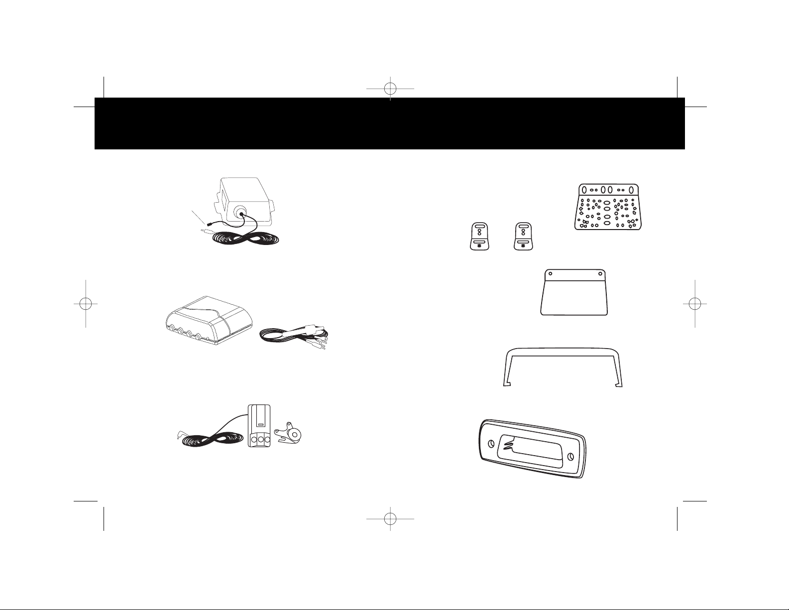
Antenna Mounting Brackets And 45º Reflector
Control Panel Mount Brackets
Radar Antenna
The waterproof radar antenna with Temperature Probe is
mounted at the front of your vehicle, usually behind the grill.
Control Panel And Power Cable
The compact control panel is mounted on the dash
in a location convenient for viewing. The power
cable plugs into the control panel.
Whistler LRM-5
The LRM-5 (Laser Receive Module) is mounted inside your
vehicle using the windshield bracket or Hook and Loop Fastener.
2
WHISTLER 3300 COMPONENTS MOUNTING BRACKETS
3
Large L
Bracket (1)
Small L
Brackets (2)
45º Reflector
(For use when
mounting antenna
in vertical position.)
Hanging
Bracket
Temperature Probe
Thru Dash
Bracket
3300 Installation Instructions 10/4/00 9:37 AM Page 5
Page 4
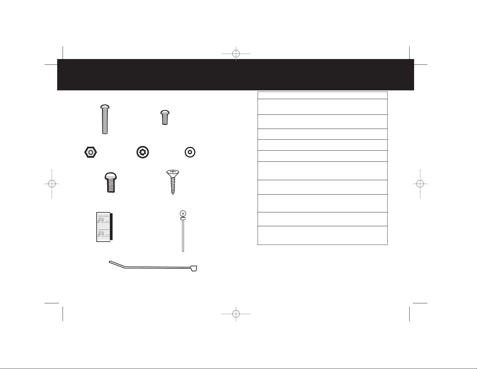
Reference Description/Use Qty.
A Bolt #10-32 x 1-1/4" 2
• Fastens Large L or Small L
Bracket to vehicle support.
B Bolt #10-32 x 1/2" 2
• Fastens Small L to Large L
Bracket (optional approach).
C Nut #10-32 4
• Use with #10-32 bolts.
D Lock Washer 4
• Use with #10-32 bolts.
E Flat Washer 2
• Use with #10-32 bolts.
F Sheet metal Screw #6 x 3/4" 7
• Fastens Large L/Small L Bracket
or 45º Reflector to radar antenna.
Mounts Temp. Probe.
G Sheet metal Screw #4 x 5/8" 2
• Fastens Hanging Bracket
to interior vehicle surface.
H Hook & Loop 1/2" x 1" 1
• Fastens LRM-5 to back
of rearview mirror when
windshield bracket is not used.
I Mounting Cable Tie 1
• Secures Temperature Probe
to vehicle.
J 4" Cable T ie 5
• Secures cable from radar
antenna at various locations in
engine compartment.
Note: If mounting fasteners are missing from your package,
call 1-800-531-0004 for replacements.
5
MOUNTING FASTENERS
4
Bolt
#10-32 x 1-1/4"
Bolt
#10-32 x 1/2"
Nut
#10-32
Lock
Washer
Flat
Washer
A
B
Sheet metal
Screw
#6 x 3/4"
Sheet metal
Screw
#4 x 5/8"
Hook and
Loop Fastener
C
D
E
F
G
H
J
I
Mountable
Cable Tie
4" Cable Tie
MOUNTING FASTENERS
3300 Installation Instructions 10/4/00 9:37 AM Page 7
Page 5

7
6
INSTALLATION OF RADAR ANTENNA INSTALLATION OF RADAR ANTENNA
General Information
The radar antenna is waterproof and designed to be mounted
at the front of your vehicle. In most vehicles the best mounting
location is directly behind the grille; however, other locations
which provide concealment and/or protection of the antenna
may be acceptable. Radar signals will pass through non-metallic
materials such as fiberglass and plastic, however, be sure to
mount the receiver away from any metal, as it will block the
receiver’s antenna. Because the optimal location for mounting
the antenna varies by vehicle type, the hardware supplied is
designed to offer a wide variety of mounting options. We suggest
choosing the option that enables the antenna to be securely
fastened and provides the ANTENNA window adequate forward
visibility.
NOTE: Use of hardware that is not supplied or DRILLING
into the case will cause damage to the receiver and void
the warranty.
Antenna Mounting Brackets
There are two types of mounting brackets for the antenna:
Large L (1) and Small L (2). The Large L bracket fastens to the
antenna using two or more screws (#6 x 3/4"). Slide the screw
through the hole on the flange of the antenna and then tighten
into the metal bracket (do not over tighten). The Large L
Bracket may be fastened to the antenna in a variety of positions
as shown on page 7.
The layout of holes on the large L Bracket accommodates multiple antenna
mounting positions.
This arrangement provides flexibility for fastening the antenna
/bracket assembly to your vehicle in a manner that allows the
antenna window (ANTENNA) to have a forward looking view of
the road ahead.
The Small L Brackets (2) may also be fastened to the antenna
in different positions as shown below:
The Small L Brackets may be fastened to any of the six holes on the antenna.
Use one #6 x 3/4" screw to fasten each Small L Bracket to the
antenna. Again, do not over tighten the screws.
In some situations it may be advantageous to use both the Large L
and Small L Brackets to install the antenna in a vehicle.
3300 Installation Instructions 10/4/00 9:37 AM Page 9
Page 6

8
INSTALLATION OF RADAR ANTENNA INSTALLATION OF RADAR ANTENNA
9
Horizontal Mounting
When mounting the antenna in a horizontal position (or on an angle
between), remember to keep the ANTENNA window as close to
perpendicular as possible to the road surface (ANTENNA window
should not be angled up toward the sky or down toward the road
surface).
Mounting Vertical (with 45º Reflector)
For vehicles that do not have sufficient clearance behind the grille
(about 5") to mount the antenna in a horizontal position, the 45º
Reflector should be used.
The 45º Reflector is attached to the antenna with two screws (#6 x 3/4")
on the side of the antenna housing marked ANTENNA. Slide the
screws through the corner holes on the flange of the antenna housing
and then tighten into the metal reflector (do not over tighten).
Large L and Small L Brackets may be used in combination.
The Small L Brackets are fastened to the Large L Bracket using
the #10-32 x 1/2" bolts, #10-32 nuts and lock washers.
To fasten the Large L or Small L Brackets to your vehicle, mark
the supporting structure through the appropriate holes in the
brackets, then drill the holes in the supporting structure with a
13/64" drill bit. Attach the bracket(s) to the supporting structure
using two bolts (#10-32 x 1-1/4") and corresponding nuts, flat
washers, and lock washers. You may also use 2 #6 sheet metal
screws. Because rough road surfaces can cause excessive
vibration or bouncing, be certain to fasten the bracket(s)
securely to your vehicle.
Horizontal Or Vertical Mounting Of Antenna
The antenna can be attached to the vehicle in a horizontal or
vertical position, or at any angle between these two points.
Select the position that allows you to fasten the antenna to
your vehicle in the most secure manner.
Radar antenna mounted in horizontal position.
Best mounting angle for optimum detection of all types of radar guns.
3300 Installation Instructions 10/4/00 9:37 AM Page 11
Page 7

10
11
INSTALLATION OF RADAR ANTENNA
Mount the antenna to the vehicle such that the ANTENNA window
is facing the road surface, sky, right or left of the vehicle, and the
reflector has an unobstructed view of the road ahead.
Radar antenna mounted(vertical) with 45º Reflector.
Mounted in this position, radar signals are reflected into the
ANTENNA window.
Mounting the Temperature Probe
Find a location that is far enough away from engine and radiator
heat but still in the airflow for the vehicle. Mounting the Probe too
close to these heat areas will give a false high temperature.
• Attach the mountable tie wrap (supplied) to the Temperature
Probe as shown.
• Mark location for Probe, then drill a hole using a 7/64" drill bit.
Attach Probe with tie wrap in the correct orientation using the #6
x 3/4 screws.
NOTE: Mount the Probe so that there is space between the Probe
and the mounting area.
Do
not mount Probe directly to metal area.
Mounting Location
Temperature
Probe
Mountable Tie Wrap
Probe Cable
Antenna Cable To Control Panel
Once the antenna is installed, run the cable along the edge of the
engine compartment to the firewall. Find a location in the firewall
where other wires (or the speedometer cable) enter the passenger
compartment and feed the stereo jack connection through. Be
careful not to interfere with or disconnect other wires, cables, or
mechanical systems of your vehicle while routing the antenna cable.
Also, keep the antenna cable away from any areas in the engine
compartment that may become hot. Cable ties are provided to
secure the antenna and Temperature Probe cables at various points
in the engine compartment.
General Information
The LRM-5 (Laser Receive Module) provides both front and rear laser
reception. Mount the LRM-5 with the 3-lens array facing forward
(down the road) and the single lens facing behind. This approach
offers the greatest protection, since you will most often be traveling
into a laser signal, rather than away from it when laser speed
enforcement is encountered. For effective protection, make sure the
LRM-5 has an unobstructed view forward and behind, and that it is
not placed behind metallic sun screens.
Mounting The LRM-5
The LRM-5 can be mounted to the front windshield using the
windshield bracket supplied.
INSTALLATION OF LRM-5
3300 Installation Instructions 10/4/00 9:37 AM Page 13
This side
facing traffic
Antenna window
Signal
Page 8

12 13
Before using, attach the suction cup and rubber bumpers (2) to
the metal bracket. If necessary, you may bend the metal bracket
in order to position the LRM-5 correctly (3-lens array facing
forward, single lens facing behind.)
LRM-5 mounted with windshield bracket.
Using Hook & Loop Fasteners, the LRM-5 may also be mounted
to the back side of your rearview mirror. Be careful not to block
the rear facing lens when mounted in this manner. Also, clean
the appropriate surfaces with isopropyl alcohol before adhering
the adhesive side of the fastener to those surfaces.
LRM-5 mounted to rearview mirror with Hook & Loop Fasteners.
INSTALLATION OF LRM-5 INSTALLATION OF CONTROL PANEL
General Information
The control panel may be mounted using the Under Dash
Bracket or Hook & Loop fastener supplied. As an alternative, you
may also use a Through Dash Bracket. When choosing a mounting
location, consider your needs for ease of viewing the display,
accessibility of controls (remember Mute Mode may be used
frequently), and concealment.
Control Panel Mounted With Under Dash Bracket
Fasten the Under Dash Bracket to your vehicle’s dash with the
two #4 x 5/8" sheet metal screws provided. A 5/64” drill bit
should be used to drill pilot holes for the screws. Use the holes in
the bracket to mark the location for pilot holes.
Once the bracket is fastened to your vehicle, the control panel
can be attached to it. However, we suggest connecting all cables
to the back of the control panel before snapping it into the bracket.
See page 15 for proper placement of cables.
Control panel snaps into rather than slides onto the Under Dash
Bracket.
HIGHWAY
HIGHWAY
3300 Installation Instructions 10/4/00 9:37 AM Page 15
Page 9

Control Panel Mounted With Hook & Loop Fasteners
Fasteners can be used to mount the top or bottom of the control
panel to your vehicle. Before adhering the adhesive side of the
fastener to a surface, clean that surface with isopropyl alcohol.
Use of Hook & Loop simplifies control panel installation.
Control Panel Mounted With Through Dash Bracket
Installation instructions are provided with the bracket. We
recommend using a professional installer if you are not familiar
with customized dashboard installations.
14 15
1. Power Port
2. Radar 1 Port
3. Radar 2 Port
4. Voice Port
5. Laser Port
INSTALLATION OF CONTROL PANEL INSTALLATION OF CONTROL PANEL
Antenna Cable Connection
The stereo connector (straight end) on the end of the antenna
cable plugs into Radar 1 port (2) on the back of the control panel.
LRM-5 Cable Connection
After mounting the LRM-5, conceal the cable and plug the
stereo jack connector (right angled end) into the port on the
back of the control panel labeled LASER port (5).
Power Cable Connection
The power cable has a plug on one end which connects to the
back of the control panel at the port labeled PWR port (1). At
the other end of the power cable the power and ground wires
are separated. The ground wire has a “U” type connector which
should be fastened to a metal surface. Look for an existing
screw or bolt under the dash to use as a grounding point. The
power wire has a spade type connector which should be connected
to a switched +12 volt DC circuit in your vehicle’s fuse box. A
switched circuit is one that has power when your vehicle is on,
but has no power when your vehicle is off. Connect the “U”
type connector to the ground point selected, attach the power
cord plug to the control panel area marked “PWR” then touch
the power wire to the +12 volt DC switched power source
selected; if the control panel sounds the self test sequence,
then all connections are correct.
3300 Installation Instructions 10/4/00 9:37 AM Page 17
Page 10

16 17
Added Protection From Behind
For drivers interested in gaining increased detection range
when radar is transmitted from behind, the Whistler 3300 can
be upgraded with a second antenna. This antenna is mounted
facing rearward and can be purchased from many Whistler
retailers or directly from Whistler; ask for the SWRA-3300
(Superwideband Remote Antenna), Part Number 202964.
The Whistler 3300’s control panel is designed to operate with
the SWRA-3300; the RADAR 2 port (3) is the input for the
SWRA-3300 cable. On model 3300 an asterisk is displayed next
to the Band ID (K ||| |||) when radar signals are detected. The
SWRA-3300 detects all radar guns operating on X, K, and
superwideband Ka frequencies.
Instructions and mounting hardware for installing the SWRA3300 are included with the unit.
More Volume
Real Voice Module (P/N 202971) can be used to articulate Band
ID, Safety Warning and Feature Selection. Plugs into VOICE
port (4).
NOTE: This is the only audio option that can be plugged into
the Whistler 3300. Any other device may damage the unit and
void the warranty.
The Whistler 3300 is expertly engineered and designed to exacting
quality standards to provide you with reliable, trouble-free operation. If your unit has been correctly installed following the
guidelines in this manual, but is not operating optimally , please
refer to the troubleshooting guide below.
PROBLEM: No display or audio
•Check fuse in power cable, replace if necessary.
•Check fuse in fuse box, replace if necessary.
•Make sure power cable is properly grounded.
PROBLEM: Unit alarms when using vehicle equipment or
electrical accessories (brakes, power mirrors/windows,
directionals, horn, etc.)
•Check condition of vehicle’s electrical system, including
battery and alternator.
•Install a filter capacitor (470mfd. 25 volt or larger capacitor
value) where power connection is made.
PROBLEM: Audio alerts are not loud enough.
•Cancel Auto Quiet Mode or City Mode.
•Check audio level setting.
PROBLEM: Display shows R1 error.
Also see Pg. 18-19 of Owner’s Manual.
•Warning communicates “loss of link” between control
panel and front antenna (RADAR 1).
•Check antenna connection at back of control panel.
•Contact factory, if you suspect antenna is defective.
OPTIONAL ACCESSORIES TROUBLESHOOTING GUIDE
*
3300 Installation Instructions 10/4/00 9:37 AM Page 19
Page 11

18
TROUBLESHOOTING GUIDE
PROBLEM: Display shows R2. Also see Pg. 18-19 of Owner’s Manual.
•Warning communicates “loss of link” between control
panel and rear antenna (RADAR 2); occurs only if rear
antenna has been installed.
•Check antenna connection at back of control panel.
•If no rear antenna is installed, perform the factory reset
procedure outlined in the owner’s manual.
•Contact factory is you suspect rear antenna is defective.
PROBLEM: Display shows R2 ON?
•Rear antenna connected to RADAR 2 port. Press DARK
for yes or CITY for no.
•R2 was shut off by a factory reset. See Reset Features
section of owner’s manual.
If difficulties occur which cannot be solved by information in this
Troubleshooting Guide, please call Whistler Consumer
Relations at 1-800-531-0004 before returning your unit for service,
or contact us via email: info@whistlergroup.com.
NOTES
3300 Installation Instructions 10/4/00 9:37 AM Page 21
Page 12

NOTESNOTES
3300 Installation Instructions 10/4/00 9:37 AM Page 23
 Loading...