

Page 1
WHISPERPOWER BV
Kelvinlaan 82
9207 JB Drachten
Netherlands
Tel.: +31-512-571550
Fax.: +31-512-571599
www.whisperpower.com
USER’S MANUAL
Piccolo 2/8, 3/10/12 and 3+/15
genverters for marine use
V3, Sept 2020
Page 2

CONTENTS
CONTENTS
1 INTRODUCTION .......................................................................................................................................................................... 4
1.1 General .................................................................................................................................................................................. 4
1.2 Service and maintenance ...................................................................................................................................................... 4
1.3 Guarantee ............................................................................................................................................................................. 4
1.4 Liability .................................................................................................................................................................................. 5
1.5 Identification ......................................................................................................................................................................... 5
1.5.1 General ............................................................................................................................................................... 5
1.5.2 Identification plate ............................................................................................................................................. 5
2 GENERAL INFORMATION ............................................................................................................................................................ 6
2.1 Safety .................................................................................................................................................................................... 6
2.1.1 General ............................................................................................................................................................... 6
2.1.1 Warnings and symbols ....................................................................................................................................... 6
2.1.2 Scope of regulations ........................................................................................................................................... 6
2.1.3 Maintenance & repair ........................................................................................................................................ 6
2.1.4 Electrical safety .................................................................................................................................................. 6
2.1.5 Installation .......................................................................................................................................................... 6
2.1.6 Operation ........................................................................................................................................................... 7
2.1.7 Fire and explosion .............................................................................................................................................. 7
2.1.8 Dangerous substances ........................................................................................................................................ 7
2.1.9 Warning regarding life support applications ...................................................................................................... 7
2.2 Transport, lifting and storage ................................................................................................................................................ 7
2.3 Features ................................................................................................................................................................................ 8
2.3.1 General ............................................................................................................................................................... 8
2.3.2 Construction ....................................................................................................................................................... 8
2.3.3 Control ................................................................................................................................................................ 8
2.3.4 Installation .......................................................................................................................................................... 8
2.3.5 Documentation .................................................................................................................................................. 8
2.4 Main components to identify ................................................................................................................................................ 9
2.4.1 Piccolo 2/8 .......................................................................................................................................................... 9
2.4.2 Piccolo 10/12 .................................................................................................................................................... 10
2.4.3 Piccolo 3+ /15 ................................................................................................................................................... 11
3 TECHNICAL INFORMATION ....................................................................................................................................................... 13
3.1 Explanation of functional parts ........................................................................................................................................... 13
3.1.1 Control system ................................................................................................................................................. 13
3.1.2 AC Permanent Magnet Alternator ................................................................................................................... 13
3.1.3 Engine ............................................................................................................................................................... 13
3.1.4 Starter battery charging ................................................................................................................................... 13
3.1.5 Piccolo PMG control ......................................................................................................................................... 13
3.1.6 Piccolo DDC and Piccolo 10, 12 and 15 control ................................................................................................ 13
3.1.7 Fuel Specification ............................................................................................................................................. 14
3.1.8 Biodiesel ........................................................................................................................................................... 14
3.1.9 Lubricating oil ................................................................................................................................................... 14
3.1.10 Cooling liquid .................................................................................................................................................... 15
3.2 Technical data ..................................................................................................................................................................... 16
4 OPERATION .............................................................................................................................................................................. 18
4.1 General ................................................................................................................................................................................ 18
4.2 Programmable speed .......................................................................................................................................................... 18
4.3 Control panels ..................................................................................................................................................................... 18
4.4 Operating instructions ........................................................................................................................................................ 18
4.4.1 Daily check of oil level ...................................................................................................................................... 18
4.4.2 Summarized operating instructions (daily use) ................................................................................................ 18
4.4.3 Extended operating instructions ...................................................................................................................... 19
5 MAINTENANCE ......................................................................................................................................................................... 21
5.1 Maintenance intervals ........................................................................................................................................................ 21
5.2 Alternator ............................................................................................................................................................................ 21
5.3 Engine ................................................................................................................................................................................. 21
5.3.1 Preliminary instructions ................................................................................................................................... 21
5.3.2 Bleeding the fuel lines ...................................................................................................................................... 21
5.4 Regular maintenance .......................................................................................................................................................... 21
5.4.1 General precautions ......................................................................................................................................... 21
2 Piccolo 2/8, 3/10/12, 3+/15 — June 2020 — EN
Page 3

CONTENTS
5.4.2 Servicing after break-in .................................................................................................................................... 22
5.4.3 Changing engine oil and oil filter cartridge ...................................................................................................... 22
5.4.4 Checking the battery ........................................................................................................................................ 22
5.4.5 Adjusting the V-belt tension ............................................................................................................................. 22
5.4.6 Draining water from the fuel tank .................................................................................................................... 23
5.4.7 Replacing the raw water pump impeller .......................................................................................................... 23
5.4.8 Replacing the fuel filter .................................................................................................................................... 23
5.4.9 Changing the air filter element ........................................................................................................................ 23
5.4.10 Checking hoses and electrical connections ...................................................................................................... 23
5.4.11 Servicing after 800 hours and beyond .............................................................................................................. 23
5.5 Putting out of service .......................................................................................................................................................... 23
6 TROUBLESHOOTING ................................................................................................................................................................. 24
6.1 General ................................................................................................................................................................................ 24
6.1.1 Piccolo 8 ........................................................................................................................................................... 24
6.1.2 Piccolo DDC version .......................................................................................................................................... 24
6.1.2.1 General ............................................................................................................................................................. 24
6.2 Alternator/ electrical faults ................................................................................................................................................. 25
6.2.1 Troubleshooting table for alternator ............................................................................................................... 25
6.2 Engine faults ........................................................................................................................................................................ 25
6.2.1 General ............................................................................................................................................................. 25
6.2.2 Troubleshooting table for engine ..................................................................................................................... 25
6.2.3 Warnings .......................................................................................................................................................... 28
6.2.4 Service address ................................................................................................................................................. 28
7 SPARE PARTS ............................................................................................................................................................................ 29
Maintenance log .................................................................................................................................................................................. 31
Supplier’s Declaration of Conformity/Incorporation
Piccolo 2/8, 3/10/12, 3+/15 — March 2020 — EN 3
Page 4

Art. no.
Description
49005005
Piccolo 2/8 (Kubota Z482) 230V
49005055
Piccolo 3/8 (Kubota Z482) 120V
49009005
Piccolo 10 (Kubota D722) 230V
49009055
Piccolo 10 dual phase 120/240VAC (D722)
49006005
Piccolo 12 dual phase 120/240VAC
49007005
Piccolo 3+/15 dual phase 120/240VAC (D1105)
INTRODUCTION
1 INTRODUCTION
1.1 GENERAL
This manual serves as a guideline for the safe and effective
operation, maintenance and possible correction of minor
malfunctions of genverters for marine applications
manufactured and marketed by WhisperPower.
It is therefore essential that every person who works on or with
the genverters should be familiar with the contents of this
manual, and that he/she should carefully follow the instructions
contained herein. Both safety and durability depend very much
on the correct identification, installation and the correct
understanding of ratings, features, design, maintenance and
operation procedures.
The information, specifications, illustrations and statements
contained within this publication are given with our best
intentions and are believed to be correct at the time of going to
press.
All of the specifications, provisions and instructions contained in
this manual apply solely to standard versions of genverters
delivered by WhisperPower.
This manual is valid for the following models:
For other models, see other manuals available on our website:
www.whisperpower.com.
Our policy is one of continued development and we reserve the
right to amend any technical information without prior notice.
Whilst every effort is made to ensure the accuracy of the
particulars contained within this publication neither the
manufacturer nor the distributor or dealer in any circumstances
shall be held liable for any inaccuracy or for the consequences
thereof.
1.2 SERVICE AND MAINTENANCE
Regular service and maintenance should be carried out
according to the directions in this manual. For service and
maintenance, turn to the manufacturer or a dealer.
1.3 GUARANTEE
WhisperPower guarantees that this genverter has been built
according to the principles of good workmanship, according to
the specifications in this manual and according to European
Community safety regulations.
During production and prior to delivery, all of our genverters
are tested and inspected.
This genverter’s correct operation is subject to guarantee. The
period and conditions of this guarantee are laid down in the
general conditions of delivery as registered with the Chamber of
Commerce and Industries for the North of the Netherlands
number 01120025 and are available on request. The guarantee
period is two years, limited to 1000 running hours. Some aspects
of our guarantee scheme are given here in more detail.
Guarantee does not cover failures caused by misuse, neglect or
faulty installation.
Example 1: Faulty installation
Seawater entering the engine is the most common cause of
damage to combustion engines (both propulsion and generator
engines) in boats. The entry of water must be avoided under all
conditions. Be aware that the conditions in blue water sailing can
be extreme. Refer to the installation manual for instructions but
remember these are for guidance only as many factors influence
the installation of the genverter. The ultimate responsibility will
always be with the owner. If in doubt, ask!
Example 2: Misuse
Long term running with no load or too little load can cause the
exhaust to get choked with soot or carbon. Cleaning the exhaust
is not covered by guarantee.
Example 3: Neglect
Sometimes the seal of the raw water pump starts leaking. Mostly
this begins with a little drip and it slowly gets worse. Regular
visual inspection of the genverter is necessary to prevent
damage from occurring due to a leaking water pump. When
serious damage is discovered after weeks of neglect, guarantee
claims will not be honoured.
Example 4: Neglect
A WhisperPower genverter has an option for an auto start/stop
mode or interval mode. WhisperPower cannot be held
responsible for damage caused by the genverter running
unattended. Oil changes must be carried out according to the
maintenance schedule.
Guarantee means that faulty parts are repaired or replaced free
of charge. If necessary the whole genverter unit will be
exchanged. Labour necessary to complete repairs on board a
vessel by an authorized service engineer is covered, but is limited
to a reasonable number of hours and reasonable rates in relation
to the actual repair work that has to be done.
Travel expenses and travel hours are not covered, neither is the
labour required to take a genverter out of a vessel or for
reinstallation. There is no cover for labour needed to get access
to the genverter, for example to remove equipment or parts of
the vessel’s structure or hull.
Goods to be delivered under guarantee will be invoiced. Only
after the faulty goods are returned will the invoice be credited.
Payment in advance may be required or guaranteed by credit
card. If the faulty goods show that the failure was not covered by
guarantee, a credit will not be issued. For example, if a Printed
Circuit Board is returned with clear damage caused by water,
guarantee will be refused.
4 Piccolo 2/8, 3/10/12, 3+/15 — June 2020 — EN
Page 5
Freight costs to deliver spares by normal mail or carriers are
Any work contrary to the guidelines, instructions
and specifications contained in this user’s manual
and the corresponding installation manual, may
damage the genverter and prevent it from
meeting its specifications. In all these cases the
guarantee may become invalid. Use original spare
parts only!
Automatic start/stop: WhisperPower cannot be
held responsible for damage caused by the
genverter running unattended using the autostart/stop mode or interval mode.
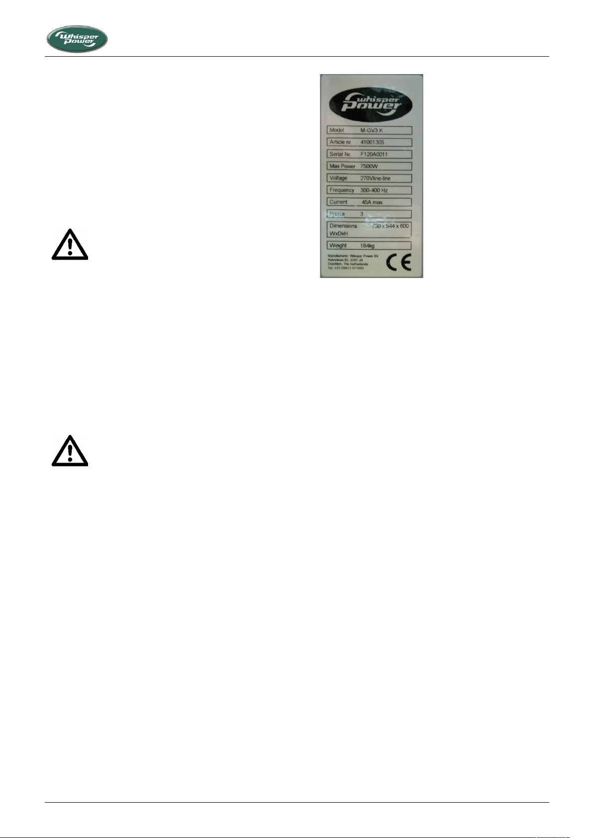
Figure 1: Identification plate
covered under guarantee. Special services like express mail,
overnight delivery, etc. are not covered. Taxes and duties are not
covered. For shipments to remote areas any additional costs
incurred over normal carriage will be invoiced to the customer.
The cost for returning faulty goods is not covered by guarantee.
If any problem arises which could be subject of guarantee,
procedures should be followed as described in the guarantee
conditions, unauthorized repairs could lead to further damage
and violate the guarantee conditions.
1.4 LIABILITY
WhisperPower does not accept responsibility for damage,
injuries or casualties which are the result of operation of the
genverter in specific conditions bringing dangers which could not
be foreseen, or could be avoided by additional measures.
WhisperPower does not accept liability for damage due to use of
the genverter, possible errors in the manuals and the results
thereof.
1.5 IDENTIFICATION
1.5.1 General
Before using this genverter it is very important to identify the
model correctly. To communicate for service or ordering parts it
is also essential to correctly identify the genverter. For the daily
operation of the genverter it is necessary that the operator
knows the correct specifications as well.
1.5.2 Identification plate
All required identification data are on the identification plate.
The identification plate also mentions some basic features of the
genverter.
SERIAL NUMBER: The identity of the genverter is given by the
serial number. Using this number, the manufacturer can trace
the specifications of the genverter.
POWER: The identification plate gives the maximum load in kW,
i.e. kVA calculated with power factor one. When calculating a
load one should always take into account the power factor or cos
phi of this load. The resulting load should not exceed the nominal
power as shown on the identification plate. Power is rated at an
ambient temperature of 25°C. For higher temperatures the
genverter has to be de-rated.
Piccolo 2/8, 3/10/12, 3+/15 — March 2020 — EN 5
INTRODUCTION
VOLTAGE: The Permanent Magnet Alternator (PMA) generates a
variable voltage between 250V and 400V. Depending on the type
of installation, this is converted by a DC PowerCube or an AC
Power Module for Genverter
FREQUENCY: The Permanent Magnet Alternator output
frequency is considerably higher than in in common alternating
current installation. The DC PowerCube and WP-PMG (Power
Module for Genverter), however, are designed to generate very
stable DC and AC outputs from the PMA output.
CURRENT: The maximum allowed current at the specified
voltage and power factor.
PHASE: The number of live wires running from the genverter.
WEIGHT: The net dry weight (approximately) in kg. This is
without fuel, oil, cooling liquid, packaging and external
installation equipment.
CE-MARKING: The “CE” symbol shows that the genverter is built
according to European Community safety regulations. This
includes the regulations regarding safety of pleasure craft,
electric safety and electric magnetic compatibility (EMC) and
other relevant directives. Under the Machinery Directive, the
genverter is an incomplete machine and can only comply after
installation; refer to the Declaration included in this manual.
Safety is also a matter of installation, utilization and operating
conditions. See also 2.1.
It is recommended to consult the manufacturer before changing
a factory setting. If the genverter involved is not new, former
users may have changed the settings. Check the settings when
there is any doubt.
Page 6
WARNING
This warning symbol draws attention to special
warnings, instructions or procedures which, if not
strictly observed, may result in damage or
destruction of equipment, severe personal injury
or loss of life.
WARNING
Moving machinery. This symbol indicates that a
potential hazard exists caused by moving parts
and draws attention to special warnings,
instructions or procedures which, if not strictly
observed, may result in severe personal injury or
loss of life.
WARNING
This danger symbol refers to toxic danger caused
by Carbon monoxide (CO) and draws attention to
special warnings, instructions or procedures
which, if not strictly observed, may result in severe
personal injury or loss of life.
DANGER
This danger symbol refers to electric danger and
draws attention to special warnings, instructions
or procedures which, if not strictly observed, may
result in electrical shock which will result in severe
personal injury or loss of life.
A procedure, circumstance, etc. requiring extra
attention.
In certain situations, additional measures may be
necessary. Be aware of wet conditions, explosion
hazards, etc.
WARNING
When service has to be carried out while the
engine is running, be aware of moving parts.
If the genverter is switched off during
maintenance and/or repair activities, it should be
secured against unexpected and unintentional
switching on:
• remove the DDC fuse from the local control
panel
• remove the connections to the batteries
• be sure that third parties cannot reverse the
measures taken.
Warning signs indicate parts which could be live.
The alternator output (which is the inverter input)
can be as high as 400 Volt and is very dangerous.
The only way to get access to the high voltage
parts is with the help of tools. Never run the
genverter when there is access to these parts.
Touching these parts may result in electrical shock
which will result in severe personal injury or loss
of life.
Do not use the genverter when the vessel is inside
a boat house or in other enclosed areas.
GENERAL INFORMATION
2 GENERAL INFORMATION
2.1 SAFETY
2.1.1 General
The user must always:
• have access to the user's manual;
• be familiar with the contents of this manual.
This applies in particular to the paragraphs on safety.
2.1.1 Warnings and symbols
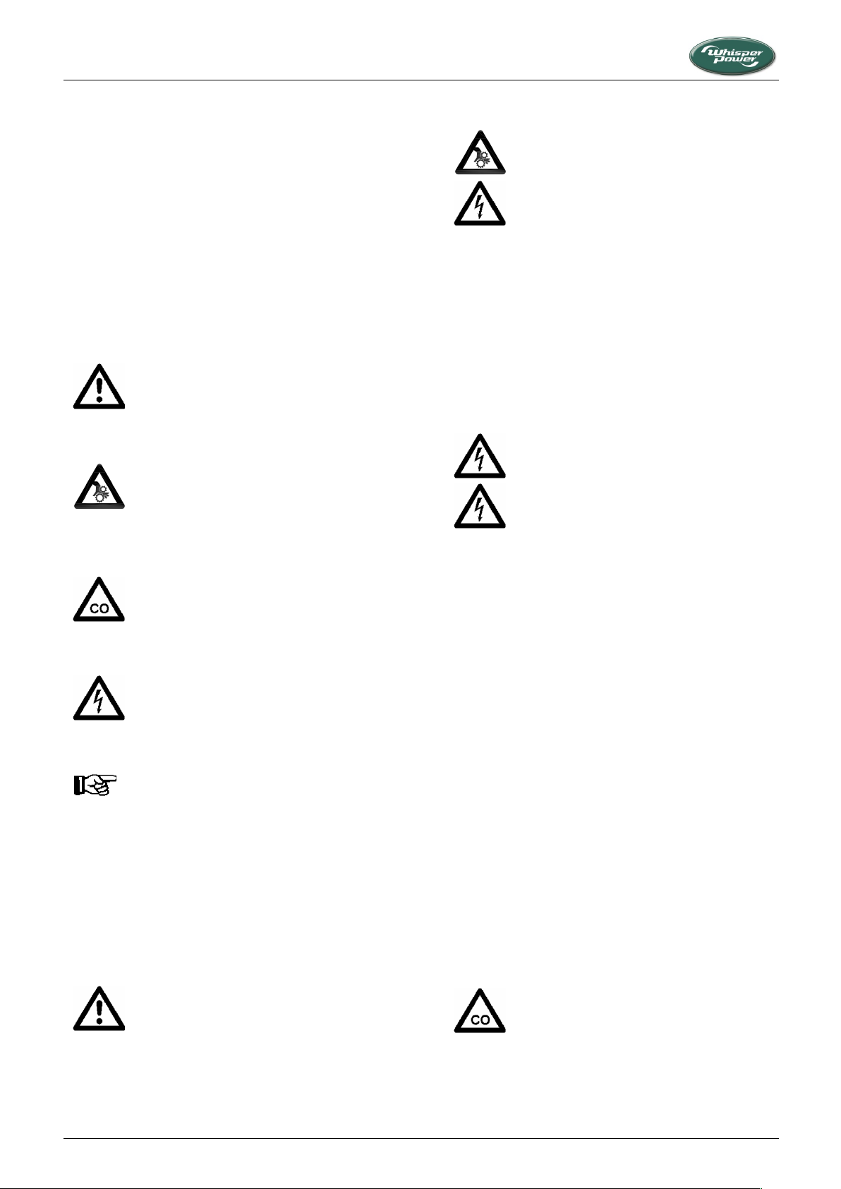
Safety instructions and warnings are marked in this manual by
the following pictograms:
2.1.3 Maintenance & repair
Use original spare parts only. Always consult the manual before
carrying out maintenance.
2.1.4 Electrical safety
2.1.2 Scope of regulations
When correctly installed and used under normal conditions, this
genverter fulfils EC safety regulations. This genverter could be
part of an installation or could be used in a way that additional
regulations of the EC or other authorities have to be taken into
account. Refer to the declaration of conformity/incorporation
included in this manual.
• Check all wiring at least once a year. Defects, such as loose
connections, burned cables, etc. must be repaired
immediately.
• Do not work on the electrical system if it is still connected
to a current source. Only allow changes to your electrical
system to be made by qualified electricians.
• Connections and protection must comply with local
standards.
2.1.5 Installation
WhisperPower genverters are not self-contained and have to be
properly installed. Installation involves proper ventilation, safe
electric connections, safe installation of the starting battery,
proper fitting of the cooling system and fuel pipes etc. In
enclosed areas, installation includes taking measures to outlet
exhaust fumes. Containing carbon monoxide, these are
extremely dangerous. Carbon monoxide (CO) is an invisible and
odourless gas. Inhalation produces headache, nausea or death.
Refer to the installation manual.
6 Piccolo 2/8, 3/10/12, 3+/15 — June 2020 — EN
Page 7

GENERAL INFORMATION
Nevertheless take note of the triangular signs on
the genverter indicating danger.
Fuels can be flammable. Proper handling limits the
risk of fire and explosion.
WARNING
Never use the genverter in situations where there
is danger of gas or dust explosion or where
potentially flammable products are present!
When lifting the genverter avoid any risk of
personal injuries. In particular, do not stand under
the genverter.
2.1.6 Operation
WhisperPower genverters have no external moving parts like
fans and V-belts. The fan of the radiator unit is covered by a grid.
The hot parts of the engine are covered by the sound shield and
therefore these genverters are very safe when the sound shield
is closed.
• The genverter should be operated by authorized personnel
only.
• Be aware of hot parts and especially parts of the exhaust
system and the cooling system.
• If the genverter is unsafe, fit danger notices and disconnect
the battery positive (+) lead so that it cannot be started until
the condition is corrected.
• Do not attempt to operate the genverter with a known
unsafe condition. Disconnect the battery positive (+) lead
prior to attempting any repairs or cleaning inside the
enclosure.
• Always consult the manual before carrying out
maintenance.
• Do not change the settings without consulting the
manufacturer. Keep a record of setting changes in this
manual.
2.1.7 Fire and explosion
2.1.8 Dangerous substances
Fuels, oils, coolants, and battery electrolyte can be hazardous to
personnel if not handled properly. Do not swallow or have skin
contact with these liquids. Do not wear clothing that has been
contaminated by fuel or lubricating oil.
The gaskets used in the genverter are free of asbestos. However,
gaskets containing asbestos can still be found. Avoid inhaling
particles of this material as this may result in fatal diseases.
Therefore it is a good habit to be careful with gaskets.
On no account allow unprotected skin to come into contact with
the injector spray as the fuel may enter the blood stream with
fatal results.
Engines may be fitted with seals or O-rings manufactured from
"Viton" or similar material. When exposed to abnormally high
temperatures in excess of 315°C an extremely corrosive acid is
produced which cannot be removed from the skin. If signs of
decomposition of the material are evident, or if in doubt, always
wear heavy duty disposable gloves.
2.1.9 Warning regarding life support applications
The WhisperPower genverters are not intended to be used as a
component of any life support system unless a specific written
agreement pertaining to such intended use is executed between
the manufacturer and WhisperPower. Such agreement will
require the medical equipment manufacturer either to contract
additional reliability testing of the genverter and/or to commit
to undertake such testing as a part of the manufacturing process.
In addition the medical equipment manufacturer must agree to
indemnify and not hold WhisperPower responsible for any claims
arising from the use of the genverter in the life support
equipment.
• Avoid refilling the fuel tank while the engine is running.
When oil or fuel is leaking do not use the genverter.
• Hydrogen gas generated by charging batteries is explosive.
Ensure proper ventilation. Do not smoke and do not allow
sparks, flames, or other sources of ignition around
batteries.
• Keep a fire extinguisher on hand.
• In case of fire, do not open the sound shield. To avoid
serious injury or death from fire, shut down engines,
generator sets and blowers. However, if you do open the
sound shield, immediately discharge the entire contents of
a portable fire extinguisher into the enclosure.
• Poor electrical connections or using wiring which is not
suited for the rated currents can cause overheating and
possibly fire.
Piccolo 2/8, 3/10/12, 3+/15 — March 2020 — EN 7
2.2 TRANSPORT, LIFTING AND STORAGE
• Use soft slings to avoid damage
• The engine has a lifting eye which can be used to take the
genverter out of the enclosure. It can also be used to lift the
complete genverter including the enclosure.
• After transporting the genverter check for damage before
installation.
• Long term storage can have detrimental effects on engine
and alternator. The engine should undergo an engine
preservation procedure (refer to the maintenance chapter.)
• Condensation may occur on alternator windings. To
minimize condensation, store the genverter in a dry and
warm storage area.
• While the battery is stored it should be recharged every 12
weeks.
Page 8

GENERAL INFORMATION
2.3 FEATURES
2.3.1 General
The WhisperPower genverters combine carefully selected
engines with highly efficient Permanent Magnet alternators. The
voltages and frequencies produced, however, require the
genverter to be connected to a WhisperPower DC PowerCube or
Power Module producing clean DC or AC output. This is an
original concept, which is cost-effective as wells as easy on
installation.
2.3.2 Construction
The genverter incorporates a diesel engine which has a
permanent magnet alternator in the flywheel. The engine is
mounted on a steel base frame and mounted securely on a
double set of anti-vibration mounting pads in a sound attenuated
enclosure. The output of the power from the alternator will be
between 300V-400Hz and 400V-500Hz, depending on the engine
speed. The engine speed is set to strike a balance between fuel
efficiency and comfort. All cables and hoses are guided through
the enclosure’s sides.
2.3.3 Control
The genverter’s control system is based on microprocessor
technology. On models featuring Digital Diesel Control (DDC),
several operating modes and automatic start/stop functions can
be programmed and monitored (refer to Digital Diesel Control
user’s manual).
All functions can be set from the remote control panel, which
comes as standard with the genverter, including an RJ12
connecting cable.
2.3.4 Installation
The genverter is not self-contained and is only operable after
proper installation using additional accessories and installation
materials such as a starter battery, fuel supply and an exhaust
system.
Installation accessories are listed in the installation manual and
are available through the supplier of the genverter.
2.3.5 Documentation
Included in the delivery are:
• This user’s manual (no. 40200421)
• An installation manual (no. 40200701)
• A DDC operating manual (no. 40200801), as applicable
• A DDC quick reference guide (no. 40200142), as applicable
The user’s manual contains a list of important maintenance and
spare parts as well as a chapter on maintenance and problem
solving. Manuals in other languages are available on request.
8 Piccolo 2/8, 3/10/12, 3+/15 — June 2020 — EN
Page 9
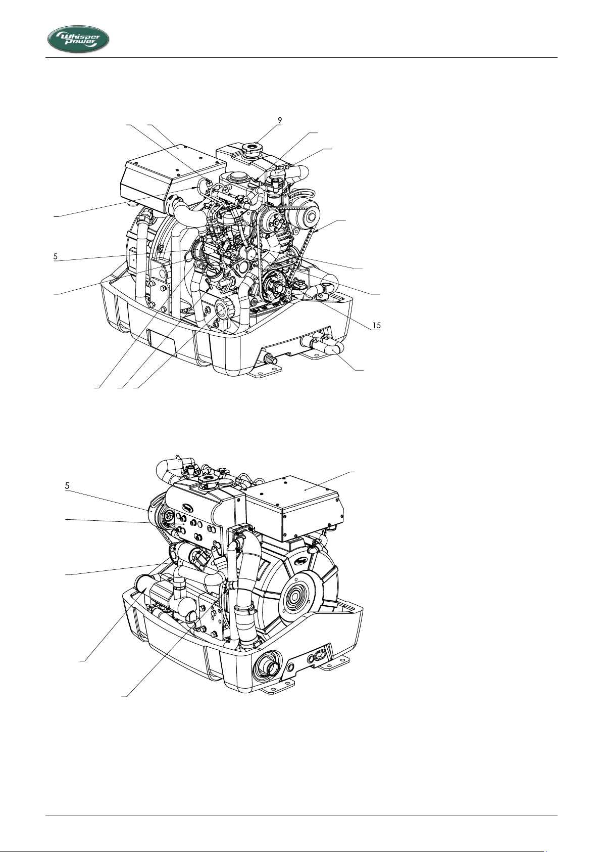
2.4 MAIN COMPONENTS TO IDENTIFY
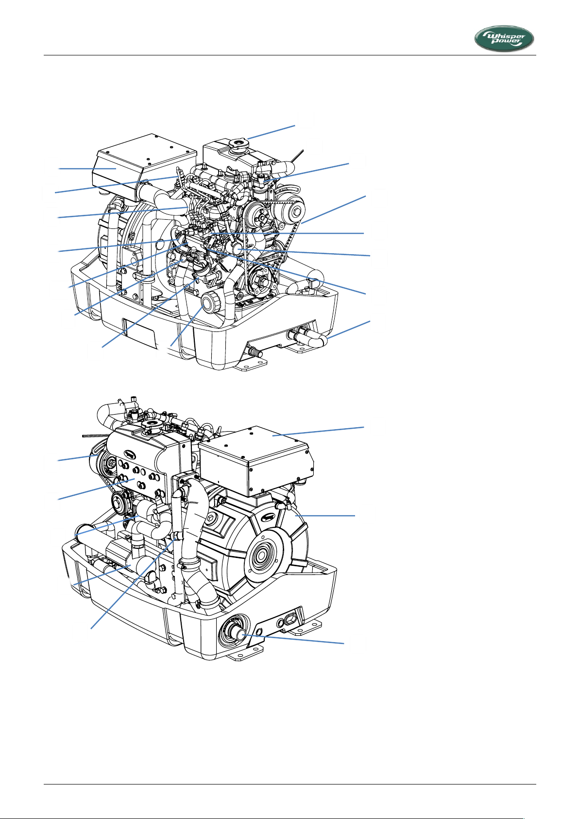
Figure 2: Piccolo 2 and Piccolo 8, service side
Figure3: Piccolo 2 and Piccolo 8, reverse view
123
4
6
7
8
10
11
12
13
14
16
1.
2.
3.
4.
5.
6.
7.
8.
9.
10.
11.
12.
13.
14.
15.
16.
1
2
3
4
6
exhaust temperature
1.
cooler
2.
starter
3.
exhaust manifold
4.
alternator
5.
6.
7.
exhaust
8.
2.4.1 Piccolo 2/8
GENERAL INFORMATION
Piccolo 2/8, 3/10/12, 3+/15 — March 2020 — EN 9
Page 10
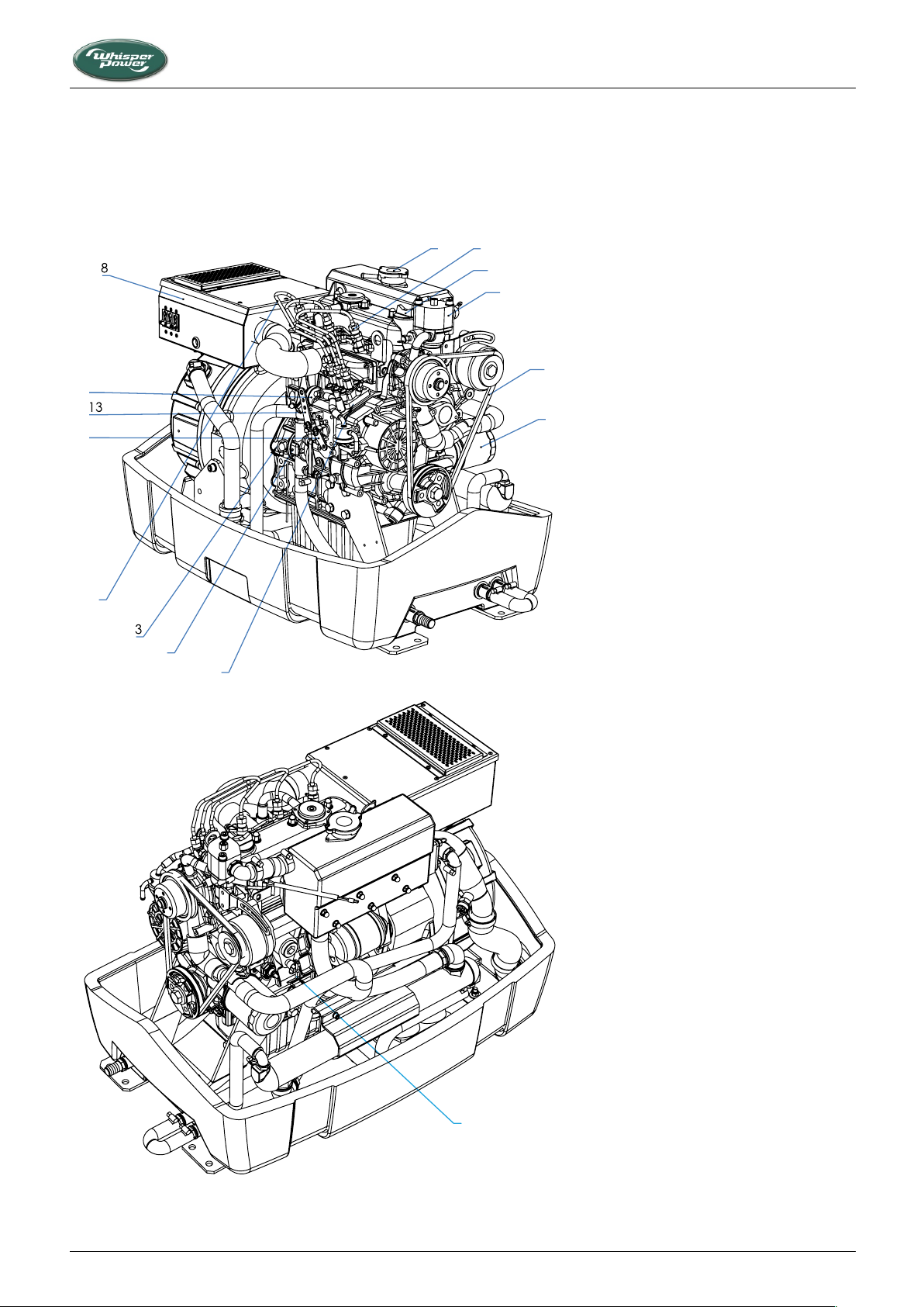
2.4.2 Piccolo 10/12
Figure 4: Piccolo 10 and Piccolo 12, service side
1. oil filter
2. coolant drain
3. oil dipstick
4. fuel injection pump
5. raw water pump
6. fuel line
7. injector (glow plug behind)
8. air filter housing
9. coolant filler cap
10. oil filler cap
11. thermostat cover
12. V-belt
13. stop lever
14. stop solenoid
15. speed control lever
16. syphon hose
1. exhaust temperature
switch
2. cooler
3. starter
4. exhaust manifold
5. alternator
6. air filter housing
7. Permanent Magnet
Alternator
8. exhaust
Figure 5: Piccolo 10 and Piccolo 12, reverse view
6
1
7
5
8
4
3
2
15
12
11
10
14
4
3
6
1
7
2
13
5
16 8 9
GENERAL INFORMATION
10 Piccolo 2/8, 3/10/12, 3+/15 — June 2020 — EN
Page 11
2.4.3 Piccolo 3+ /15
1. oil filter
2. coolant drain
3. oil dipstick
4. fuel injection pump
5. raw water pump
6. fuel line
7. injector (glow plug
behind)
8. air filter housing
9. coolant filler cap
10. oil filler cap
11. thermostat cover
12. V-belt
13. stop lever
14. stop solenoid
15. speed control lever
Figure 4: Piccolo 3+/15, service side
1
4
5
6
7
9
10
11
12
14
15
2
GENERAL INFORMATION
Piccolo 2/8, 3/10/12, 3+/15 — March 2020 — EN 11
Page 12
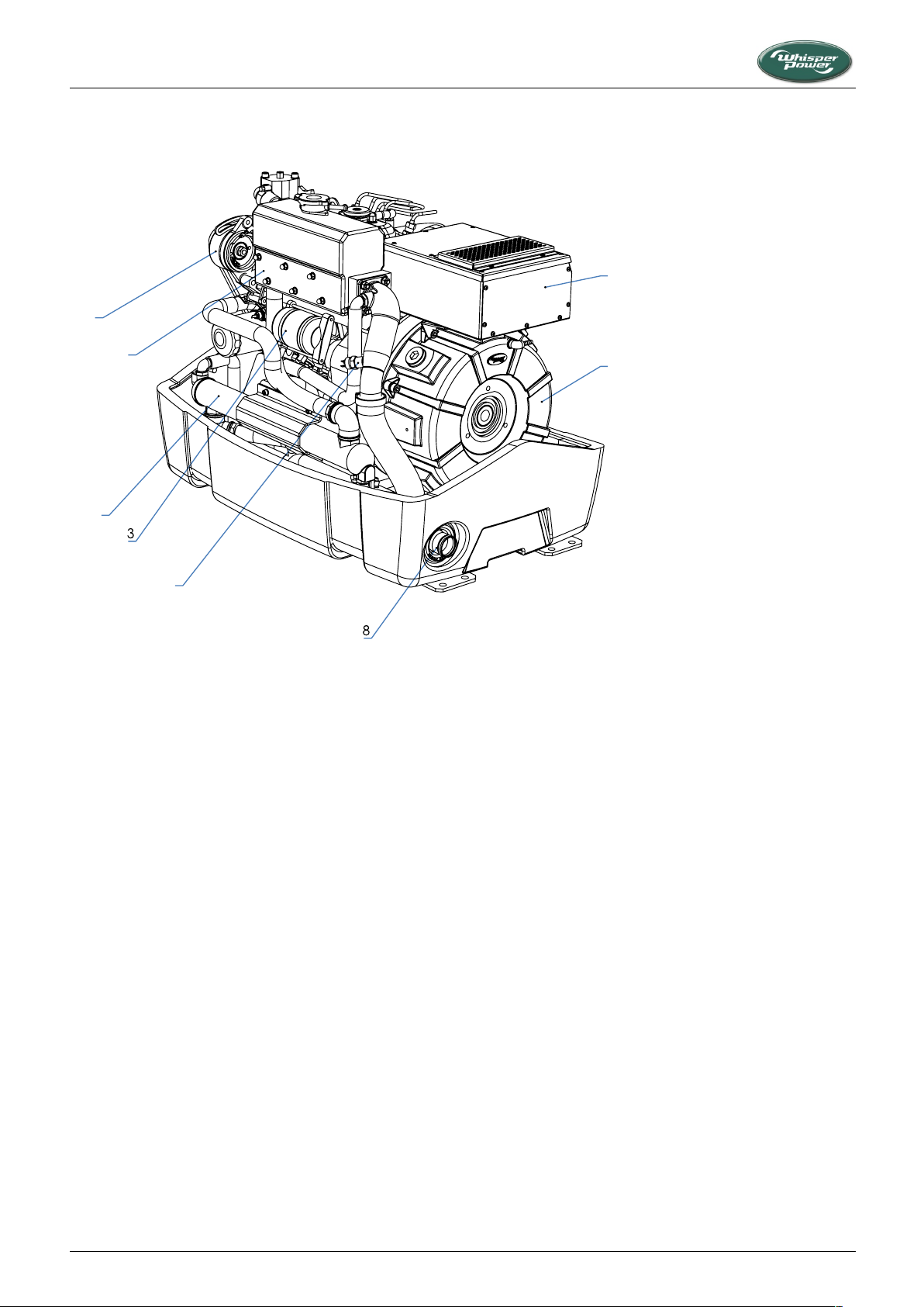
Figure 5: Piccolo 3+ /15, reverse view
1. exhaust temperature
switch (behind panel)
2. cooler
3. starter
4. exhaust manifold
5. alternator
6. air filter housing
7. Permanent Magnet
Alternator
8. exhaust
1
2
4
5
6
7
GENERAL INFORMATION
12 Piccolo 2/8, 3/10/12, 3+/15 — June 2020 — EN
Page 13
TECHNICAL INFORMATION
WARNING
The alternator magnets are very powerful.
Prevent drilling chips or metal parts from entering
into the sound shield as these may be drawn into
the alternator and cause the alternator to fail.
WARNING
The alternator’s magnetic field may cause false
compass readings. This should be taken into
account when installing a compass.
3 TECHNICAL INFORMATION
3.1 EXPLANATION OF FUNCTIONAL PARTS
WhisperPower genverters are highly advanced systems. They
combine new technologies from various fields such as engine
technology, PM alternator technology and, in the PowerCubes
and Power Modules, inverter technology.
3.1.1 Control system
The standard electrical engine control system is 12 Volt negative
earth. Non-earth return (ungrounded) is available as option.
Check your identification data to determine which system is
being used. Either system is of the "energize to run" type: it stops
when the 12 V DC voltage is taken away.
3.1.2 AC Permanent Magnet Alternator
The Three Phase Permanent Magnet Alternator is incorporated
in the flywheel and has a very high efficiency of at least 94%. The
output of the power from the alternator will be between 250V300Hz and 400V-500Hz, depending on the engine speed. As the
efficiency is very high, little cooling is needed. The alternator and
the engine use the same cooling system.
3.1.3 Engine
The genverter has a Kubota engine fine-tuned by WhisperPower.
The engine has indirect injection and was designed to meet the
highest emission standards. The cooling system can be used for
CHP (Combined Heat and Power production). Contact
WhisperPower for additional information.
Further details are in the data sheet in 3.2.
3.1.4 Starter battery charging
The engine is equipped with a 12.5A (Piccolo 8) or 40A
(Piccolo 10) alternator for charging the starter battery. The
voltage is regulated at ±14.4V.
3.1.5 Piccolo PMG control
WP-PMG POWER MODULE GENVERTER (PICCOLO 8)
Through the WP-PMG Power Module Genverter, the user can
control and operate the genverter.
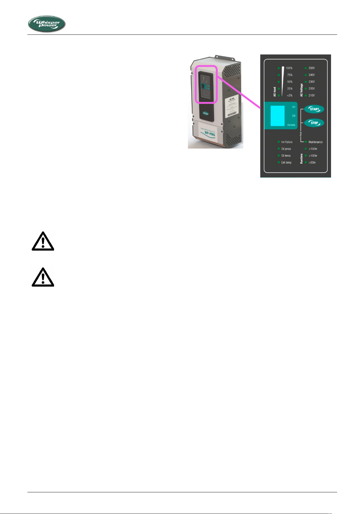
By pushing the START button on the PMG control panel (refer to
Figure 5) for two seconds, the control system is activated and will
start the engine automatically. Pushing the STOP button (again
hold two seconds) will stop the engine and the electrical system
will be deactivated.
Piccolo 2/8, 3/10/12, 3+/15 — March 2020 — EN 13
Figure 5: WP-PMG control panel (230V model shown)
The various control panels indicate the AC load. As far as PMG
operation and functionality is concerned, the reader is referred
to the PMG User’s Manual.
3.1.6 Piccolo DDC and Piccolo 10, 12 and 15 control
3.1.6.1 Alarms and shut-down
In the event of malfunctioning this will be indicated by the failure
light, details will be shown on the display and the engine will be
shut down. Three parameters are being monitored: oil pressure,
oil temperature and exhaust temperature.
Exhaust temperature too high indicates that the injection of
cooling water into the exhaust is being blocked .
All alarm switches are closed when no malfunction occurs. A
contact is cut in the event of an alarm. This means that the
genverter will not work when the alarm switches are broken or
when there is a loose wire. The system therefore is intrinsically
safe. The panel will display details about the alarm.
3.1.6.2 Control
The genverter can be operated by push buttons on the panel on
the unit or on the remote control. Pushing the START button will
activate the control system and will start the engine
automatically. Pushing the STOP button will stop the engine and
the electrical system will be deactivated. When using the
genverter in an automatic mode the engine will start when
power is demanded, e.g. because of low batteries or another
“event” that triggers the starting operation. Various automatic
modes are available through the remote control panel. Refer to
the DDC Operating manual for more information.
Page 14
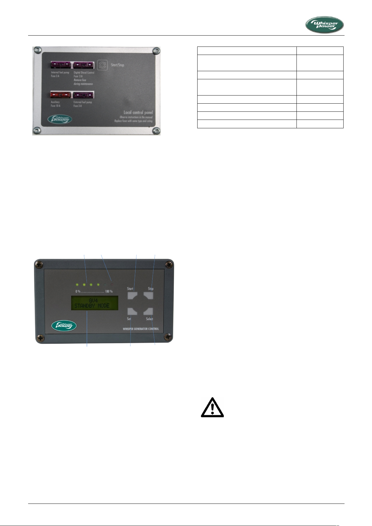
Figure 6: Local control panel
1. Start button
2. Stop button
3. Select button
4. Set button
5. Failure lamp
6. Load indicator
7. Display
Figure 7: Digital diesel remote control panel
Diesel Fuel Specification
Location
EN590
Biodiesel: EN 14214
European Union
BS 2869-A1 or A2
UK
No. 2-R, No 1-D, ASTM D975-94
Biodiesel: ASTM D-6751
USA
GB252
China
ISO 8217 DMX
International
JIS K2204 Grade No.2
Japan
KSM-2610
South-Korea
It is very important to use the correct oil
specification. Do not mix different types of oil.
Higher API class oils and synthetic oils are to be
avoided.
1
2 6 5
3
4
7
TECHNICAL INFORMATION
3.1.6.3 Remote control panel
The remote control panel is used to make the various settings. It
also displays parameters such as Voltage, Hz, Amps, and many
others (refer to the DDC manual for details).
The connection between the remote control panel and the
genverter control unit is made using plug-in connectors. A 10 m
communication cable is in the standard supply. If necessary, a
longer or shorter cable can be supplied. Multiple remote control
units can be put in parallel by using the connectors on the back
of the units (refer to installation instructions).
Diesel pre-heater
Optionally, a diesel pre-heater can be installed. This is a useful in
extremely cold conditions. In this case the fuel filter will be inside
the enclosure and there will be a heating element upstream of
the filter preventing the formation of paraffin crystals in the
diesel and clogged filters as a result. The system’s operation is
temperature-dependent and is controlled by a separate switch
to turn it “on” or “off”.
3.1.8 Biodiesel
The use of diesel fuels to a maximum blend of 5% (by volume) of
Fatty Acid Methyl Esters (FAME) known on the market as B5
diesels is allowed as far as these fuels comply with EN 14214
(Europe) or ASTM D-6751 (USA), as appropriate.
Biofuels should be supplied by recognized and authorized
suppliers only. ”Self-blended fuels” may cause engine damage
and will affect warranty.
Please note that free methanol in FAME may result in corrosion
of aluminium parts. Free water in FAME may result in choked fuel
filters and injectors and may result in increased bacterial growth.
3.1.9 Lubricating oil
1 Specification:
The oil must be suitable for oil changes as specified in the
maintenance chapter. The engine must be run on heavy duty
lubricating oil meeting the requirements of API class CF, CF-4,
CH-4, CI-4 or CI-4 plus . It is recommended to use lubricating oil
from WhisperPower or a well-known brand.
3.1.7 Fuel Specification
The engine must only be used with diesel fuel oil conforming to
the standards for use in modern diesel engines. It is essential that
the fuel should be free from water and contaminants. The
following specifications must be complied with:
14 Piccolo 2/8, 3/10/12, 3+/15 — June 2020 — EN
2 Oil viscosity:
We recommend 10W40 multi grade oil. In very cold or hot
conditions, a special grade could be applied according to the
Viscosity Chart below:
Page 15
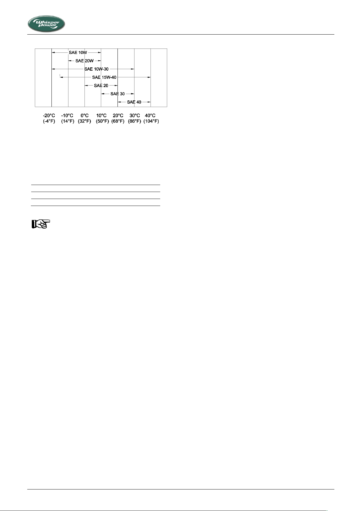
Figure 8: Viscosity chart
Piccolo 2/8
2.1 L
Piccolo 3/10/12
3.2 L
Piccolo 3+/15
4.0 L
Do not overfill with lubricating oil as this may have
a detrimental effect on engine performance.
3 Oil capacity:
The content of the crankcase and oil filter, is as specified below
(approximate data):
TECHNICAL INFORMATION
4 Lubricating oil pressure:
• Minimum at idle: 49 kPa (0,5 kgf/cm2 - 7psi).
• Normal at 3000 rpm: between 147 and 490 kPa (1,5 up to
5 kgf/cm2 - 21 up to 71 psi).
• Minimum at 3000 rpm: 98 kPa (1,0 kgf/cm2 - 14 psi).
3.1.10 Cooling liquid
The genverter is cooled by cooling liquid. Use only long-life type
G12+ cooling liquid in order to minimize maintenance. The
capacity of the engine’s cooling system is approximately 3.5
litres. When the cooling is based on keel cooling or radiator
cooling the capacity of these coolers and piping has to be taken
into account.
Initially, the engine can be filled via the filling cap on the exhaust
manifold. Fill up till the level is just below the filling cap. Filling of
the alternator cooling system and additional filling of engine
cooling system has to be done via the expansion tank. When the
engine is on temperature the liquid will expand and the
redundant liquid will be pressed into the expansion tank. This
tank has to be filled up till the mark.
Piccolo 2/8, 3/10/12, 3+/15 — March 2020 — EN 15
Page 16
Genverter Model
Piccolo 8
Piccolo 8 with DDC
Piccolo 10
Piccolo 12
Piccolo 15
genverter based on
Kubota Z482
genverter based on
Kubota Z482
genverter based on
Kubota D722
genverter based on
Kubota D1105
General information
System output
8kVA/6kW
10kVA/
8kW
12kVA/
10kW
15kVA/12kW
Peak power 200msec
200%
200%
200%
200%
200%
Rpm range
2500 .. 2800rpm
2500 .. 2800rpm
2500 ..
2800rpm
2800..
3300rpm
2000 .. 2600rpm
Low rpm setpoint
1800rpm
1800rpm
2400rpm
2400rpm
1500rpm
Max rpm setpoint
3200rpm
3200rpm
3200rpm
3600rpm
3000rpm
Typical rpm
2400 .. 2600
2000 .. 2600rpm
Sound level @ 7m
54dBA
58dBA
Sound level @ 1m
65dBA
74dBA
Cooling
Intercooling
Exhaust
Wet type, 40mm (except ..030)
Speed governor
Mechanical
Starter battery capacity
12V / 80Ah
12V / 90Ah
Standard supplies
fuel filter, fuel lift pump, user and installation manuals
(models featuring DDC: digital remote panel, 10 m cable)
Available options
installation kits, non-earth return (ungrounded), spare part kit, longer or shorter DDC cables
Mechanical specifications
Dimensions (l × w × h)
660 × 550 × 662mm
770 × 550 × 622mm
875 × 570 × 690mm
Dry weight incl. sound shield
155kg [keel-cooled: 147kg]
175kg [keel-cooled:
167kg]
187 kg [keel-cooled: 200kg]
PMG dimensions (h × w × d)
420 × 196 × 148mm
451 × 200 × 174mm
451 × 200 × 174mm
PMG weight
7.2kg
9.9kg
22.25 kg
Color
RAL9010 signal white, RAL9020 metallic black
Engine
Engine model
Kubota Z482
Kubota D722
Kubota D1105
Emission Regulation
Tier 4, EPA
Engine performance
intermittent
SAE J1349
9.32kW @ 3600rpm
14.0kW @ 3600rpm
18.7kW @ 3000rpm
Engine performance
continuous
SAE J1349
8.05kW @ 3600rpm
12.15kw @ 3600rpm
16.4kW @ 3000rpm
Number of cylinders
2
3
3
Displacement
0.479 l
0.719 l
1.123 l
Bore & stroke
67 × 68mm
78 × 78.4mm
Air intake system
Naturally aspirated
Air consumption
< 0.95 m3/min
< 1.22 m3/min
1.46 m3/min
Fuel oil
Diesel fuel oil (ASTM No. 2-D)
Fuel consumption @ full load
275 g/kWh
Engine cooling
Indirect water cooled (keel-cooling closed)
Alternator
12,5A
40A
40A
Operating principle
Energize to run
Starter power requirement
0.8 kW
1.0 kW
Nominal operation voltage
12VDC
Monitoring and control
ECU in Power
Module
Digital Diesel Control
Digital Diesel Control
Digital Diesel Control
Protections
Oil temperature and pressure, exhaust/coolant temperature [dry/wet exhaust]
Local control
PMG only
Start/stop & maintenance
Service interval oil change
200 h
Lubricant
At least CF
Oil capacity
Approx. 2.1 l
Approx. 3.2 l
Approx. 3.8 l
Approx. 4.0 l
TECHNICAL INFORMATION
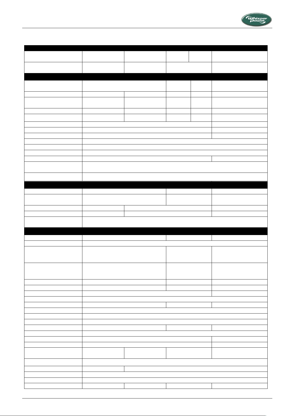
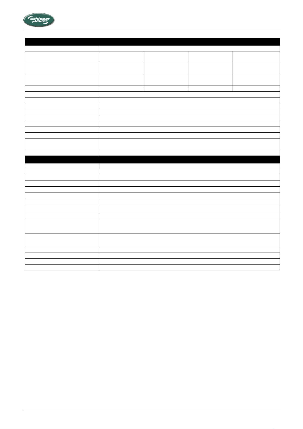
3.2 TECHNICAL DATA
16 Piccolo 2/8, 3/10/12, 3+/15 — June 2020 — EN
Page 17
TECHNICAL INFORMATION
(Alternator
Type
Permanent Magnet Alternator PM
Model
HV/SAE5,
300VAC, 400Hz, 15A
HV/SAE5,
300VAC, 400Hz, 15A
HV/SAE5,
300VAC, 400Hz, 15A
HV/SAE5,
450VAC, 400Hz, 40A
Output voltage per phase (Delta),
no load @ 25˚C
118V @ 1800rpm
236V @ 3600rpm
118V @ 1800rpm
236V @ 3600rpm
118V @ 1800rpm
236V @ 3600rpm
240V @ 1800rpm
450V @ 3000rpm
Output frequency
240Hz @ 1800rpm
480Hz @ 3600rpm
240Hz @ 1800rpm
480Hz @ 3600rpm
240Hz @ 1800rpm
480Hz @ 3600rpm
240Hz @ 1800rpm
400Hz @ 3000rpm
Nominal power (torque)
40 Nm
40 Nm
40 Nm
60 Nm
Configuration
3-phase, Star (for WP-PMG) or Delta (for DC PowerCube)
Nominal efficiency
94%
Cooling
Radiator cooling
Nominal coolant temperature
40 .. 80˚C
Bearing, coupling
Single end bearing, flex plate
Rotor concept
Inner rotor type
Number of phases
3-phase
Insulation class
H
Maximum allowed winding
temperature
175˚C
High voltage test
3000V
Regulations and Directives
CE conformity
EMC directive
EMC 2004/108/EC
Emission
EN 55022 (Class A/B household/light industrial use)
Harmonics
EN 61000-3-2 (<16A, Class A)
Dips, variations, flicker
EN 61000-4-11, EN6100-3-3 (designed to meet)
Immunity
EN 61000-6-2, marine suitable or better
LV directive
LVD 2006/95/EC
Safety
EN 60950 Safety of information technology equipment
EN 60335-1 Safety of household and similar electrical appliances, Part 1
EN 60335-2-29 Household and similar electrical appliances – Safety - Particular requirements
for battery chargers
Vibration and shock levels
(designed to meet)
EN 68-2-6, 5-50Hz velocity, max. 20mm amplitude, suitable for marine and mobile high
vibration environments
E-marking (designed to meet)
Automotive EMC 2004/104/EC
EN (designed to meet)
EN 60945
ABYC (designed to meet)
American Boat & Yacht Council
UL or CSA (designed to meet)
UL 458
Piccolo 2/8, 3/10/12, 3+/15 — March 2020 — EN 17
Page 18
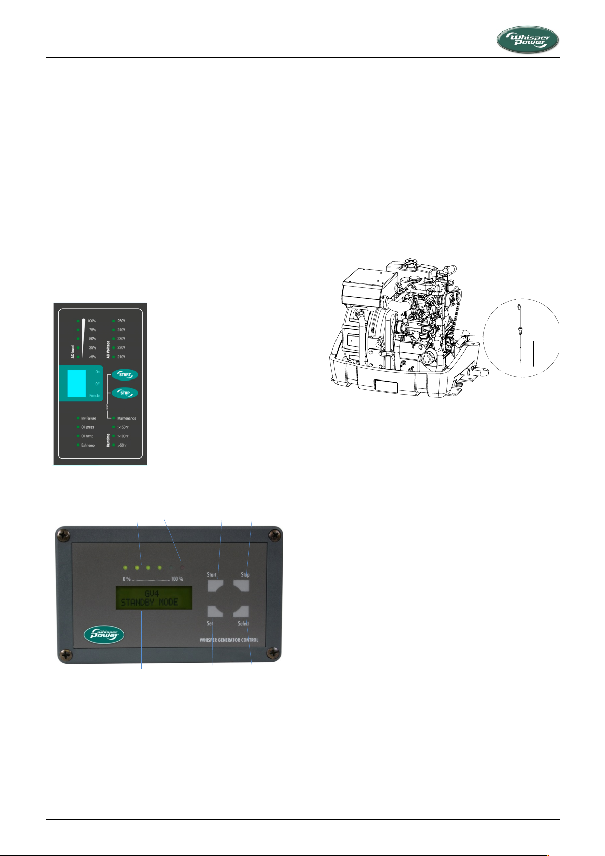
Figure 9: WP-PMG local panel (230V version shown)
1. Start button
2. Stop button
3. Select button
4. Set button
5. Failure lamp
6. Load indicator
7. Display
Figure 10: Digital diesel remote control panel
Figure 11: Oil dipstick (similar on all models)
A
1
2 6 5
3
4
7
OPERATION
4 OPERATION
4.1 GENERAL
The genverter is operational after full installation and filling up
with fuel, engine lubricating oil and cooling liquid, connecting the
battery and connecting the digital remote control panel, if
applicable.
4.2 PROGRAMMABLE SPEED
At the time of commissioning, the engine rpm are set to meet
the output requirements of the installation.
4.3 CONTROL PANELS
The genverter is usually operated either from the PMG control
panel (Piccolo 8) or from the DDC remote control panel.
4.4 OPERATING INSTRUCTIONS
4.4.1 Daily check of oil level
Be sure to keep the oil level between upper and lower limits of
the oil gauge. Too much oil may cause a drop in output or
excessive blow-by gas, while too little oil may seize the engine's
rotating and sliding parts.
Procedure:
1 Check the engine oil level before starting or more than 5
minutes after stopping the engine.
2 Remove the oil dipstick, wipe it clean and reinsert it.
Take the dipstick out again, check the oil level gauge and
reinsert the dipstick.
18 Piccolo 2/8, 3/10/12, 3+/15 — June 2020 — EN
3 If the oil level is too low, remove the oil filler plug, and add
new oil to the prescribed level.
4 After adding oil, allow the oil to come down to the oil pan
before checking the oil level again.
4.4.2 Summarized operating instructions (daily use)
Routine "pre-start" checks:
1 Check oil level and cooling liquid level.
2 Water inlet (all valves open).
3 For systems incorporating PMG: power source selector
switch (off/shore power/generator power) in “off” position,
or switch of all consumers in the usual way. If a Whisper
Switch of Transfer System Switch is installed, this operates
automatically.
4 Switch on battery switch (if installed).
5 Fuel valve: open.
Starting:
Push the start button and hold for one (DDC) or two (PMG)
seconds to initiate the fully automatic starting procedure.
In operation checks:
1 Check for abnormal noise or vibration
2 Check the output parameters on the remote control display
3 Check sea water flow at exhaust outlet
Page 19

OPERATION
Never use ether or gasoline to facilitate a cold
start as it could damage the engine.
Neither remove the battery while the engine is
running nor remove any electrical cable while the
battery is connected to the circuit. Only
disconnect the battery with the engine stopped
and all switches in "OFF" position.
4 For systems incorporating PMG: switch power source
selector to “generator” position. If a Whisper Switch of
Transfer System Switch is installed, this operates
automatically.
5 Before loading the generating set up to its maximum, have
it run warm. Continuous load should be restricted to 70 %
of maximum load.
Stopping the genverter:
1 If the genverter has been running under full load for a
longer period, do not shut it down abruptly. Reduce the
electrical load to about 30% of the rated load and let it run
for around 5 min.
2 Press the STOP button and hold for one (DDC) or two (PMG)
seconds.
3 Close the inlet sea water valve.
4 Switch to another AC power source, if available.
4.4.3 Extended operating instructions
Check when starting the first time or after a longer period of rest:
1 If there is any damage caused by transport or installation.
2 Check if the installation conforms to the installation
instructions.
3 Ensure the engine is free to turn without obstruction.
4 Check all hoses and hose connections for leaks.
5 Check all cables and terminal connections.
Routine "pre-start" checks:
1 Check engine oil level. The genverter switches off in the
event of insufficient oil pressure. Even when the oil level is
too low, the oil pressure can be high enough not to trip an
alarm. Do not run the engine with the oil below the lowest
mark, because a smaller volume of oil will become
contaminated considerably quicker than a larger volume.
Moreover, a low level may affect cooling. Therefore, we
recommend daily oil-checks. Check oil level prior to starting
the engine or at least 5 minutes after the engine has
stopped.
2 Check for leakages.
3 Switch off all devices.
4 Switch on the battery switch (if installed).
Starting the genverter:
By pushing the start button and holding it for one (DDC) or
two (PMG) seconds, the electric system is activated. You can
monitor the procedure on the display of the remote control
panel. First, the fuel pump will prime the fuel for a few
seconds (settable); the starter will then crank the engine
until it starts. While starting the alarms are blocked (this is
Piccolo 2/8, 3/10/12, 3+/15 — March 2020 — EN 19
achieved by pushing the Start button). The alarms are
reactivated after 10 seconds.
Warm up the engine without load for 3 minutes. A restart
protection prevents cranking the engine when it is already
running, which could cause damage.
Checks once the engine is in operation:
1 Check for abnormal noise or vibration.
2 Check the output parameters on the remote control display.
3 Observe the exhaust at the rated load.
The exhaust must be free from soot. Do not allow the
engine to run with visible smoke from the exhaust without
investigating the cause, as this may result in an expensive
breakdown.
Engine load during longer operation:
During the first 50 hours of running, the continuous load
should be restricted to 70 % of the maximum load. Running
at no load or light load for long periods in the first 50 hours
may cause cylinder glazing and high oil consumption.
Avoid overloading the genverter. Overloading occurs when
the electrical load (demand) is so high that by the diesel
engine has trouble driving the alternator. It causes the
engine to run rough, while using oil and excessive fuel and
producing soot. The engine may even stop. The genverter
should therefore be loaded at the maximum rated power
for short periods (2-3 hours) only! The high peak current is
meant for the ability to start electrical devices that need a
high current for starting especially electric motors and
compressors (from a still stand state).
In order to prolong the genverter’s life expectancy, the
nominal electrical demand of the system should not exceed
70% or the genverter’s rated maximum load. Please note
this when switching on your electrical equipment!
Nevertheless, the genverter is designed so as not to
overheat, even under extreme conditions.
Do not run the genverter for very long periods at no load or
at very low load. When this is necessary, increase the load
to at least 70% for one hour in 10 hours. Long term running
at too low load will cause the exhaust to be choked by
carbon (soot).
Page 20

If the engine is not running and the ‘failure’ and
‘charging’ LEDs are blinking, press the stop
button in order to prevent the starter battery
from being drained.
OPERATION
Stopping the genverter:
1 Avoid stopping the genverter abruptly after a long period of
operation at high load. Prior to switching off the genverter,
decrease the load (i.e. turn off most electrical consumers)
and let the genverter run at low load for approx. 5 minutes
to allow the engine to cool down sufficiently. Another
reason to switch off electrical consumers prior to stopping
the genverter is the voltage drop that occurs as the engine
comes to a halt.
If the genverter is operating in a hot environment and is not
allowed to cool down, excessive heat in the engine may trip
the "high temperature" alarms. This will prevent restarting
of the engine for some time.
2 Press the STOP button for one (DDC) or two (PMG) seconds.
3 Switch to another 230V power source, if available.
20 Piccolo 2/8, 3/10/12, 3+/15 — June 2020 — EN
Page 21
5 MAINTENANCE
Service level
break-in 1 2 3 4
before
each
start
after
35-50 h
every
200 h/
6M*
every
400 h/
12M*
every
800 h/
24M*
every
1600 h/
36M*
Lubricating
oil
check oil level
l
change oil and oil filter cartridge
l
l (12M)
l l l
check lubricating oil pressure
£
Cooling
system
check cooling liquid level
l
check and clean radiator (if installed)
l l l
replace water pump impeller
l l l
check hoses
l
l
check cooling system
l/£
Exhaust
check exhaust
l
Nuts & bolts
check all and tighten where necessary
l
Electrics
check all electrical connections
l
l
l
check/adjust V-belt tension
l l l
l
check battery (acid level, connections)
l l l
l
Fuel system
drain water from tank
l l l
l
replace fuel filter
l l l
check fuel hoses
l
l
check injection nozzle(s) and injection pressure
£
check injection pump
£ (3200h)
Air supply
check air strainer and filter element
l l l
Cylinder
head
retighten cylinder head bolts and readjust valve
clearance
l/£
* Whichever comes first.
l Can be done by user. Corrective action to be taken whenever necessary.
£ WhisperPower service centre to be contacted.
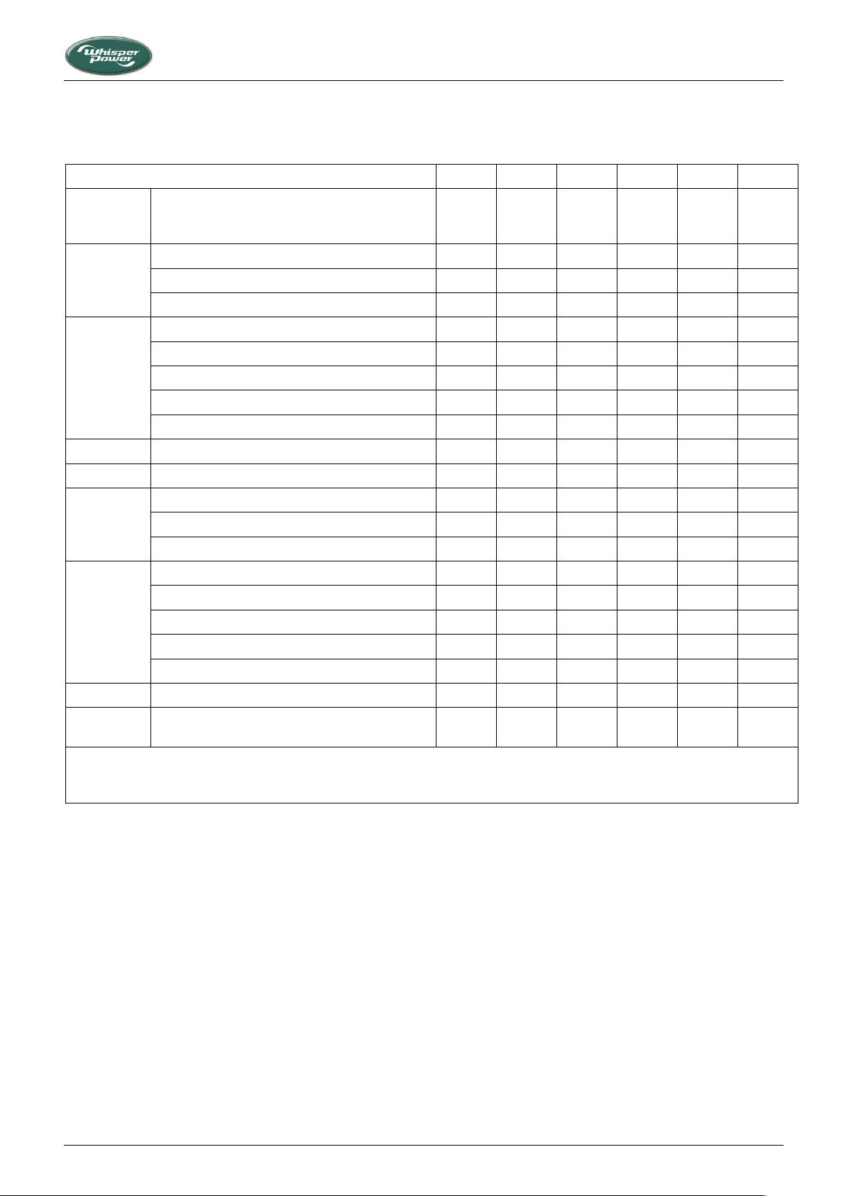
5.1 MAINTENANCE INTERVALS
MAINTENANCE
5.2 ALTERNATOR
The alternator does not require maintenance.
5.3 ENGINE
5.3.1 Preliminary instructions
The first service on the engine should be carried out after 50
running hours. This period also applies after a major overhaul.
During the first 50 hours, the engine should receive special
attention:
• Long periods of light or no load running in the first 50 hours
may lead to cylinder glazing and high oil consumption.
• For the same reason it is of the greatest importance to use
the right oil specification.
Piccolo 2/8, 3/10/12, 3+/15 — March 2020 — EN 21
5.3.2 Bleeding the fuel lines
When the engine is started up for the first time or after it has run
out of fuel, the fuel system may need to be primed. Push the start
button activating the electric system and activating the fuel
pump. When more time is needed to bleed, hold the “Start/Stop”
button on the local control panel (so not on the remote panel).
While the button is held, the pump will work, but the unit will
not start. Hold as long as necessary to bleed the system
5.4 REGULAR MAINTENANCE
5.4.1 General precautions
All regular maintenance can be carried out when the enclosure
is open. When oil and dirt have gathered in the enclosure,
measures have to be taken to prevent oil from being spilled.
Page 22
CAUTION!
Risk of personal injury, fire and/or electric shock
Standard torque chart
Size
M6x1.0
M8x1.25
M10x1.5
Nm*
10.8+1.0
25.5+2.9
49.0+4.9
* Apply 80% torque when tightening bolts to
aluminium alloy.
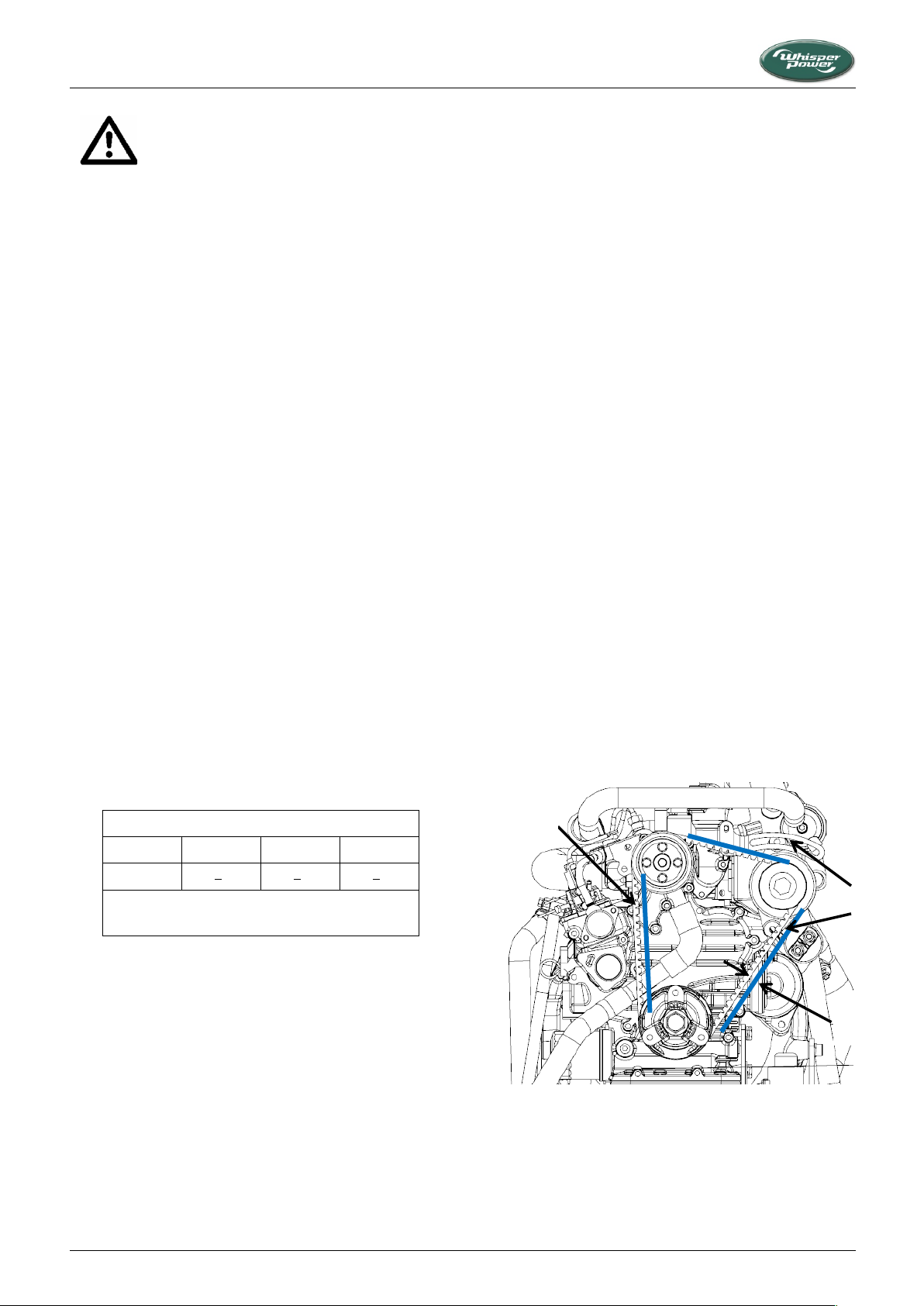
(1) Alternator belt (A) 7 mm to 9 mm under a load of 10 kgf
(2) Bolt and nut
Figure 12: Alternator belt (similar on all models)
2
1
A
MAINTENANCE
• Be sure to conduct daily checks, periodic maintenance,
refuelling or cleaning on a level surface with the engine shut
off and the control system fuse removed.
• Do not touch muffler or exhaust pipes while they are hot;
Severe burns could result.
• Allow the engine to cool down sufficiently, especially before
changing the oil or the oil filter cartridge. Oil can be hot and
cause burns.
• Contact with engine oil can damage your skin. Put on gloves
when using engine oil. If you come in contact with engine
oil, wash it off immediately.
• When changing engine oil, dispose it according to local
regulations.
• When cleaning any parts, do not use gasoline but use
regular cleanser.
• Always use proper tools, that are in good condition. Make
sure you understand how to use them, before performing
any service work.
• Be sure to tighten all bolts lest they should be loose. Tighten
the bolts by the specified torque.
• Do not put any tools on the battery, or battery terminals
may short out. Severe burns or fire could result. Detach the
battery from the engine before maintenance.
5.4.2 Servicing after break-in
• Change engine oil and replace the oil filter (refer to 5.4.3).
• Check and tighten nuts, bolts, and unions, paying particular
attention to the fuel system and using the torque chart
below.
3 Put some tissues under the oil filter cartridge.
4 Remove the old cartridge with a filter wrench.
5 Apply a film of oil to the gasket for the new cartridge.
6 Screw in the cartridge by hand. When the gasket contacts
the seal surface, tighten the cartridge not too firmly, by
hand.
7 Remove the oil filler cap on top of the engine, refill the
engine with oil (refer to 3.1.9 for specifications and
quantity). Allow the oil to come down to the oil pan and
check the oil level.
8 The oil level should be as close as possible to the maximum
level. Add (or drain) oil as necessary.
NOTE: When the genverter runs less than 200 hours a year, the
oil should be changed yearly.
5.4.4 Checking the battery
• Check battery terminals for corrosion
• Check the battery acid level (not applicable when sealed
batteries are used).
5.4.5 Adjusting the V-belt tension
Before adjusting belt tension, inspect the belt for glazing, cracks,
or dryness. A worn or damaged belt should be replaced.
1 Apply moderate thumb pressure to the belt between the
pulleys. When the belt is pressed in the middle of the span,
the deflection should be between 7 mm and 9 mm.
2 If the tension is incorrect, loosen the alternator mounting
bolts and, using a lever placed between the alternator and
the engine block, pull the alternator out until the deflection
of the belt falls within acceptable limits, then tighten the
alternator mounting bolts.
• Observe the exhaust at the normal full load. The exhaust
must be free from soot. Do not allow the engine to run with
a dirty exhaust without investigating the cause as this may
result in an expensive breakdown. When ramping up RPM
the engine will probably produce some smoke. After
stabilizing on the right RPM for the load the exhaust should
be free from soot.
• Check the electrical connections.
5.4.3 Changing engine oil and oil filter cartridge
1 Run the engine until it is on temperature, stop it and let it
cool down sufficiently to allow safe working.
2 Drain oil through the dipstick hole using a vacuum pump as
commonly used in garages.
22 Piccolo 2/8, 3/10/12, 3+/15 — June 2020 — EN
Page 23
MAINTENANCE
When handling fuel, make sure there are no open
flames or other fire hazards near the engine. Wipe
off any spilled fuel completely. Spilled fuel can
ignite and cause fire.
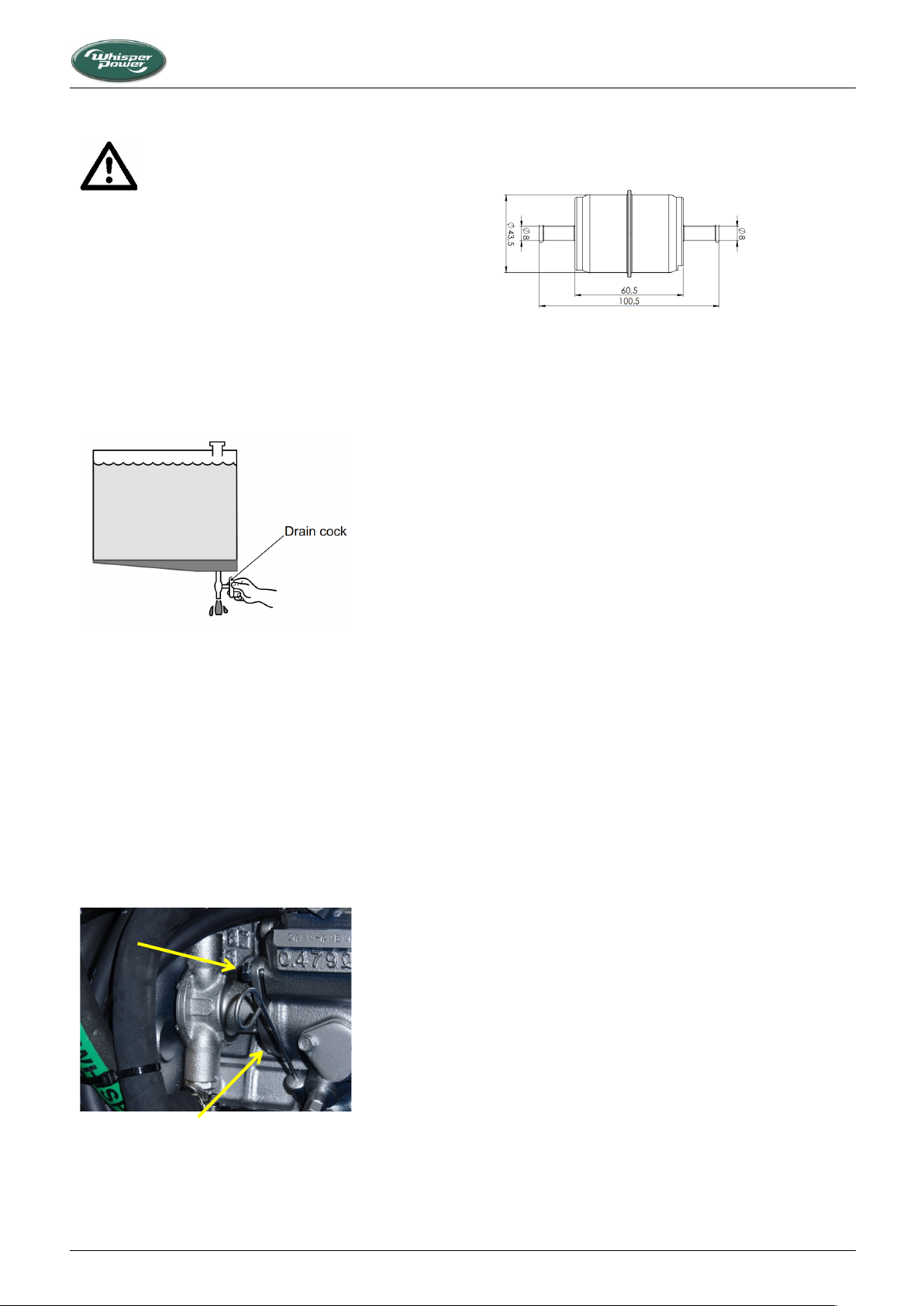
Figure 13 : Draining water from fuel tank
Figure 14: Pump housing: bolts to be unscrewed
Figure 15: Fuel filter (similar on all models)
5.4.6 Draining water from the fuel tank
If fuel gets mixed with particles of foreign matter such as dust,
dirt, or water, it can cause not only a decrease of output but also
malfunctions of the fuel system. To avoid such problems, drain
fuel tank as described below.
1. Position an oil pan (capacity of 2 litres or more) under the
drain cock of fuel tank.
2. Open the drain cock of fuel tank and drain at least 1 or 2
litres of fuel.
3. Make sure that all water and particles of foreign matter are
discharged with the fuel. Close the drain cock.
running. Before changing the filter, clamp off the supply line. The
arrow on the filter housings indicates the flow direction. Remove
the hoses from the old filter and fit the new filter.
5.4.9 Changing the air filter element
The genverter is standard supplied with an air inlet filter
element. Filter change depends on air quality.
Procedure:
1. Unscrew the cover in order to gain access to the filter.
2. Clean the foam around the element with compressed air
and clean the strainer element.
3. Check the air filter and replace it when necessary (do not
clean the air filter element).
4. Put back the cover and retighten the screws.
5.4.7 Replacing the raw water pump impeller
Both the impeller and the gasket between the pump case and
the cover should be replaced. So when ordering the impeller,
order a gasket, too (see Section 7, Spare parts). Remove the
cover to get access to the impeller. Remove the old impeller with
the help of two screwdrivers. Install the new impeller and add
some grease. Turn the blades in the direction of rotation of the
pump i.e. anti-clockwise looking at the impeller.
On M-GV 8 Piccolo genverters, the pump housing needs to be
taken from the engine in order to gain access to the cover. This
is achieved by removing the bolts shown in Figure 14. Remount
the pump after changing the impeller.
5.4.8 Replacing the fuel filter
Filter change depends on the level of contamination of the fuel,
but should be done at least every 400 running hours. A clogged
filter results in a lack of output of the engine and irregular
Piccolo 2/8, 3/10/12, 3+/15 — March 2020 — EN 23
5.4.10 Checking hoses and electrical connections
Visually check cooling hoses, fuel hoses and electrical wiring,
paying particular attention to abrasion, wear and corrosion.
Have items replaced when necessary.
5.4.11 Servicing after 800 hours and beyond
This includes the items described above, but also procedures
requiring a professional diesel mechanic. Contact your
WhisperPower Service Centre. Please find some essential data
for Kubota-based genverters below:
‒ Valve clearance: from 0.145 mm to 0.185 mm when the
engine is cold.
‒ Rocker arm bracket nut M6 × 1: from 9.81 nm to 11.2 Nm
‒ Cylinder head screw M8 × 1.25: from 38 Nm to 42 Nm.
5.5 PUTTING OUT OF SERVICE
When not using the genverter for a longer period it is
recommended to perform an engine preservation procedure.
1. Clean the engine.
2. Loosen the fuel suction pipe and fuel return and put them
in a can with preservation diesel fuel.
3. Run the engine until it is on temperature, stop it and let it
cool down sufficiently to allow safe working.
4. Drain the hot engine oil and refill with preservation oil.
5. Disconnect the battery and store it in a dry place free of
frost and charge it regularly.
6. Close inlet and outlet openings with tape.
7. Protect the genverter against the influences of bad weather
conditions.
This method of preservation will be sufficient for 6 months.
Change oil before using the engine again.
Page 24

Warning code
Problem
NO WARNING
None (no warning was detected)
LOW STARTBAT
Voltage of the start battery (BAT1) is below setting
NO BAT2
No second battery detected or voltage is below 5V while nominal voltage is set at 12V or 24V (check
connections/ fuses/ polarity of the second battery)
LOW BAT2
Voltage of the second battery (BAT2) is below setting
COMMUNICATION
Communication error between the panel and the genverter. Check the cable connection between the panel
and the control unit.
OIL PRESS HIGH
The pressure switch in the cooling system indicates a too high oil pressure
OIL PRESSURE
The oil pressure in the lubrication system is too low
ENGINE TEMP
Temperature engine oil temperature is too high
Failure code
Problem
NO FAILURE
None (no failure was detected)
COMMUNICATION
Communication error between the panel and the genverter
LOW BAT1
Starter battery voltage (BAT1) too low
PM ALTERNATOR
PM alternator voltage is not OK
EXHAUST TEMP
Exhaust temperature is too high (water-cooled exhaust only)
OIL TEMP
Oil temperature too high
OIL PRESSURE
Oil pressure failure (lubricating oil pressure too low)
SOFTWARE INV
Software failure in inverter
COMM ERROR INV
Communication between inverter and interface lost
FAILURE TO START
No start signal
TROUBLESHOOTING
6 TROUBLESHOOTING
6.1 GENERAL
If any problem should occur, check basic conditions and examine
all external wiring, switch gear and circuit breakers. Also check if
measuring instruments give the correct value. If in doubt,
measure directly on the alternator terminals with an
independent instrument.
6.1.1 Piccolo 8
In case of inverter failure or oil pressure, oil temperature or
exhaust temperature limit exceeding, the error will be indicated
on the PMG local panel (bottom left; refer to Figure 9).
6.1.2 Piccolo DDC version
6.1.2.1 General
If during the measurements mentioned in 6.1 the engine
immediately stops after starting and an error code is displayed
at the remote control panel ( “AC VOLTAGE”), the genverter can
be restarted by means of a “service start” in the service menu
(see “service start” in the user’s manual of the Digital Diesel
Control). Started this way, the genverter will keep running for 2
minutes before it stops. This offers you the possibility to carry
out measurements to investigate the cause of the failure. This
procedure should only be carried out by an experienced
electrician.
6.1.2.2 Failure codes
A failure code is displayed when a failure at the genverter is
detected. A warning code is displayed when a parameter
deviates from the setting.
24 Piccolo 2/8, 3/10/12, 3+/15 — June 2020 — EN
Page 25

6.2 ALTERNATOR/ ELECTRICAL FAULTS
Beware of parts which are live! The alternator
generates voltage up to 650 V.
Remove 3 A fuse from the control panel while
working on the genverter in order to prevent the
engine from starting.
PROBLEM
CAUSE
SOLUTION
No output (voltage) at all
• Circuit breaker "off" or faulty fuse
Check switches and fuses and measure directly on
the alternator to exclude external causes.
• Low engine RPM
Check the engine RPM and adjust (refer to special
procedures)
• Alternator failure
Check alternator resistance (1.4Ω). Contact
WhisperPower Service
Genverter output voltage too low
and RPM above 2500 while running
without load
• Alternator failure
Contact WhisperPower Service
Genverter output voltage too low
under load, but OK in no load
condition
• Genverter is overloaded
Switch off a load; reduce number of consumers
• Insufficient engine RPM
Increase minimum RPM setting
• Engine RPM drops when loaded
Refer to “Engine speed drops” section in 6.2
Remove 3 A fuse from the control panel while
working on the genverter in order to prevent the
engine from starting.
When the engine is not cranking well, starting problems almost
always originate from battery problems or poor battery cable
connections.
When the engine does crank, starting problems almost always
originate from lack of fuel or air bubbles in the fuel pipes.
A failure code is displayed when a hardware failure at the engine
is detected.
PROBLEM
CAUSE
SOLUTION
Diesel engine fails to crank; no
response at all
• Faulty fuse on the control panel
Replace fuse
• Battery switch off
Switch on
• Battery completely empty
Charge or replace battery
Diesel engine fails to crank, the
starter makes clicking noises, or the
engine cranks very slowly.
• Almost certainly this is a battery problem.
DDC display, if present, will indicate “LOW
BAT1”
Check battery voltage. Recharge the battery.
Inspect battery terminals and cables for a good
electrical connection (inspect for corrosion,
tattered wires, etc.)
6.2.1 Troubleshooting table for alternator
TROUBLESHOOTING
6.2 ENGINE FAULTS
6.2.1 General
6.2.2 Troubleshooting table for engine
Piccolo 2/8, 3/10/12, 3+/15 — March 2020 — EN 25
Page 26

PROBLEM
CAUSE
SOLUTION
• Wiring system faulty
During the normal starting process, the battery
voltage drops to 11V (with a fully charged battery).
If the voltage does not drop during starting, the
electrical connection is faulty. If the battery voltage
drops lower than 11V, then the battery has been
discharged too deep.
• Starter broken
Repair the starter motor
• Engine lubricating oil too thick
Change oil, using a lower viscosity grade
Starter is turning engine smoothly,
but engine fails to start
• Out of fuel or faulty fuel, water in the fuel
Fill up with fuel or replace with better quality
• Fuel solenoid is not opening (no “click”
can be heard)
Check wire connections and circuitry to solenoid.
(Refer to DC wiring diagram)
• Fuel lift pump is not working
Check fuel filter and fuel lift pump: clean or replace
if necessary
• Air in fuel lines
Bleed air from fuel system (refer to maintenance
section)
• Blocked injector
Have the injector tested and cleaned if necessary
• Wrong valve clearance
Adjust valve clearance
• Low compression because of dirty valves
Contact WhisperPower service department for
advice
• Loss of compression by wear out or
damage
Repair by WhisperPower service
Starter is turning engine smoothly,
but engine runs irregularly after
starting
• Faulty glow plug
Replace faulty glow plug. Consider replacing both or
all three taking into account the number of starts
completed.
Engine runs irregularly
• Lack of fuel
Check fuel supply system: fuel pump and filter
• Unsuitable or contaminated fuel
Fill up with fuel or replace by better quality
• Air in the fuel pipes
Bleed air from fuel system (refer to maintenance
section)
• Choked fuel filter
Check fuel filter and replace if necessary
• Disturbances on the electrical system/
user side
Check if electrical load is fluctuating
• Faulty fuel lift pump
Check and repair or replace
• Choked air filter
• Lack of air
Check the air intake
• Choked exhaust system, exhaust blocked
Check the exhaust piping, inspect inside of manifold
• Faulty actuator
Replace faulty parts. Contact WhisperPower service
department for advice.
• Blocked injector
Have the injector tested and cleaned if necessary
• Wrong valve clearance
Adjust valve clearance
Engine speed drops
• Genverter overloaded
Reduce the electrical load (switch off some
consumers)
• Fuel problem
Check fuel supply and clean fuel filter
• Too much lubricating oil
Drain oil to proper level
• Lack of intake air
Check air intake; clean air filter
TROUBLESHOOTING
26 Piccolo 2/8, 3/10/12, 3+/15 — June 2020 — EN
Page 27

TROUBLESHOOTING
PROBLEM
CAUSE
SOLUTION
• Choked exhaust system, exhaust blocked.
Check the exhaust piping; inspect inside of manifold
• Faulty actuator
Contact WhisperPower service department for
advice
• Defective alternator (windings or other)
Genverter must be sent to manufacturer for repair
of damaged bearing or winding
• Damaged engine
Repair by WhisperPower service
Engine does not stop on command
• Fuel solenoid is not switching off
• Loss of control
Faulty Digital Diesel Control unit. Stop the engine
manually using the stop lever.
Check wire connections to stop solenoid. Check
solenoid valve function. Replace if necessary.
Engine exhaust smokes
• Faint blue smoke - generally the result of
light load
Increase load.
• Heavy blue smoke - caused by lubricating
oil: oil level too high, worn cylinder,
stuck, broken or worn piston rings.
Check the oil level
Check the compression
• When the engine RPM is ramping up to
react at a load step some smoke may be
unavoidable.
No action required.
• Wrong setting of minimum RPM.
Readjust minimum rpm setting
• Sooty black smoke – incomplete
combustion caused by: overload, choked
air filter, air inlet temperature too high,
unsuitable fuel or water in fuel.
Check the fuel.
Check for overload
Check the air filter
• Valve clearance incorrect.
Readjust valve clearance
• Continuous running with very low load.
Increase load and have the engine run for a few
hours
Engine starts, but stops after 10 up to
30 seconds
• Faulty alarm switch/sensor
Replace the switch. By-passing the switch makes it
possible to keep running. But be aware: running
with a by-passed alarm switch can cause damage!
• Protection system stops the engine; this
can be caused by oil pressure failure,
loose wire or faulty alarm switch. Digital
Diesel Control, if fitted, will help to
indicate failure.
Refer to Chapter 3 and page 24 and the DDC
operating manual for information on the alarm
system. Bypassing a switch can help to confirm the
failure. But be aware: running with a by-passed
alarm switch can cause damage!
Engine stops by itself
• Overload or short circuit
Switch off the consumers and test for short circuit.
• Lack of fuel
Check fuel supply system: tank level, fuel lines,
pump, filter, valves, etc.
• Coolant temperature too high (>105°C)
Check cooling system
• Oil pressure low (oil pressure switch
tripped)
Check oil level
Check oil pressure and have engine repaired by
WhisperPower if necessary.
• Air or water in the fuel.
• Blocked air or fuel filter.
Check and clean
• Loss of compression by wear out or
damage.
Repair by WhisperPower service.
Piccolo 2/8, 3/10/12, 3+/15 — March 2020 — EN 27
Page 28

PROBLEM
CAUSE
SOLUTION
Loss of power
• Wrong measurement.
Check if the load is measured correctly. Does the
Amp meter show the correct value? When
calculating the load by multiplying voltage and
amps this should be done using the exact values,
taking into account the power factor of the
consumers. When in doubt, measure the power
directly using an appropriate instrument.
• Oil level too high
Drain oil to the correct level
• Choked fuel filter
Replace the fuel filter
• Choked air filter
Check air inlet openings; clean air filter
• Exhaust blocked
Check the exhaust system
• Injector blocked
Have the injector checked
• Loss of compression, sticking or damaged
piston ring
Have the compression measured
Clean or replace the rings
• Wear out of cylinder
Have the compression measured and have the
engine overhauled
Over-temperature
• Overload
Reduce the load
• Exhaust choked with carbon
• Cooling circuit failure
Clean exhaust
Contact WhisperPower service
Genverter must be shut off immediately if:
• Unusual noise comes from genverter.
• Exhaust gases suddenly colour dark.
• Engine failure warning light is on.
If you cannot correct a problem with the aid of the
troubleshooting tables, contact your WhisperPower Service
Centre or WhisperPower Netherlands for an extended service
list.
Phone: INT +31-512-571555.
TROUBLESHOOTING
6.2.3 Warnings
6.2.4 Service address
28 Piccolo 2/8, 3/10/12, 3+/15 — June 2020 — EN
Page 29

7 SPARE PARTS
article no.
• Kit A: parts for regular maintenance (marked *)
40401770
• Kit B: parts for maintenance + spare parts (marked
*+**)
40401771 (Piccolo 8)
40401772 (Piccolo 10/12)
40401864 (Piccolo 15)
DESCRIPTION
Piccolo 8
Piccolo 10 /12
Piccolo 15
Fuel filter (*)
40209030
40209030
40209030
Fuel lift pump 12V
50201161
50201161
50201161
V-belt (*)
40403120
40403120
40405120
Oil filter (*)
40403121
40403121
40405121
Air filter
40230007
40230007
50230007
WPL Oil 4 Ltr.
40222204
40222204
40222204
WPL Coolant 4 Ltr.
40222214
40222214
40222214
Water pump (complete)
40401870
40401870
40201670
Impeller + gasket / O-ring (*)
40209011
40209011
40209011
Pump repair kit A
40401471
40401471
40401475
Pump repair kit B (**)
40401472
40401472
40201274
Local control panel PCB
50209142
50209142
50209142
Digital Diesel Control Unit
40401150
40401150
40401150
Fuses 10 Amps (*)
50212170
50212170
50212170
Fuses 3 Amps (*)
50212154
50212154
50212154
Wiring loom (complete)
40401885
40401885
40401883
Digital Diesel Remote control panel
40209102
40209102
40209102
DDC Cable remote control 15 mtr.
50209133
50209133
50209133
Lube oil pressure switch
50209212
50209212
50209212
Exhaust temperature switch
50209245
50209245
50209245
Coolant temperature switch
50209208
50209208
50209208
DC Power Cables Red / Black
Included in wiring loom
Overhaul gasket kit / Seal kit
40404133
40405133
40404133
Cylinder head gasket kit
40403130
40403131
40403130
Glow plug
40403140
40201640
40403140
Injector nozzle (**)
40403150
40201650
40403150
Fuel pump (high pressure) complete
40201780
40201680
40201780
Thermostat (**)
40403145
40201645
40403145
Thermostat gasket (**)
40404138
40405138
40404138
Rocker cover gasket (**)
40404137
40201637
40404137
We recommend the following spares for service and maintenance.
SPARE PARTS
Piccolo 2/8, 3/10/12, 3+/15 — March 2020 — EN 29
Page 30
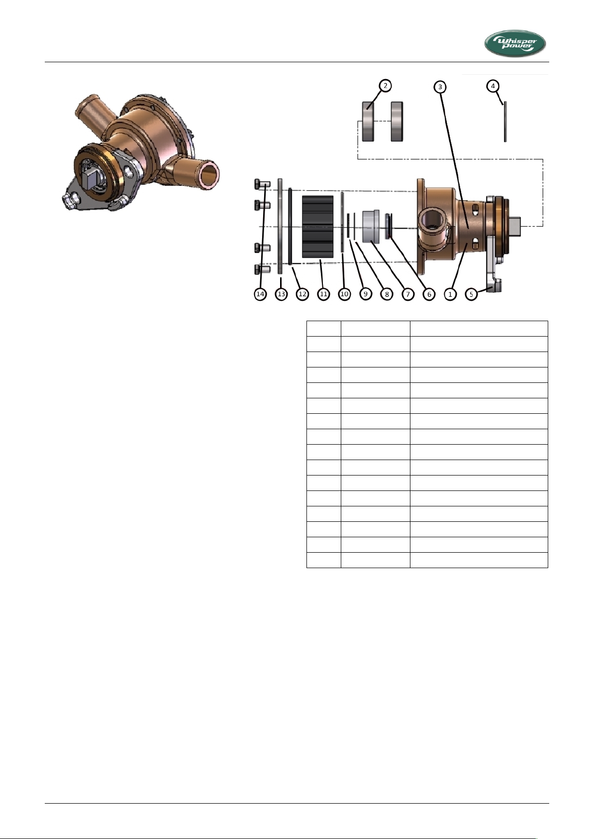
No.
Article no.
Description
40401870
Raw water pump (complete)
1 Pump body
2
40209014
Bearings (2)
3
40209021
Shaft
4
40409016
DIN 472 28mm circlip
5 Clamp
6
40409018
V-ring seal
7
40409015
Mechanical seal
8
40409017
Washer
9
40409019
DIN 12×1 external circlip
10
40209023
Impeller back plate
11
50209013
Impeller
12
40209012
54mm O-ring
13
40201810
Cover plate
14
50209018
M4×8 hex head slotted screws (6)
SPARE PARTS
Figure 17: Raw water pump housing
30 Piccolo 2/8, 3/10/12, 3+/15 — June 2020 — EN
Page 31
Maintenance log
Wartungslogbuch
Journal de maintenance
This log must remain with the generator. In the
event of a warranty claim, a copy of this log has to
be sent to the manufacturer.
Dieses Logbuch verbleibt an Bord. Im Falle eines
Garantieanspruchs muss eine Kopie an den
Hersteller geschickt werden.
Ce journal demeure à bord. En cas de prétention à
garantie, une copie est à dresser au fabricant.
Inspec
tion required at:
V
or
g
esehen
b
ei:
In
s
pection
exigée
après:
Service leve
l:
In
s
pek
t
ion
s
ka
t
ego
ri
e:
Ca
t
ég
o
ri
e
d'ins
p
ecti
o
n:
H
o
urs
on
in
dicat
o
r
:
S
t
a
n
d Betrie
b
sst
un
d
enzähler
:
E
tat
du
co
m
p
t
eur
d
'
h
eures:
Inspected by:
Prüfer:
Contrôleur:
Date:
Datum:
*) Seal, stamp & full address of responsible WhisperPower
Service Centre (only applicable to items marked £)
*) Stempel bzw. volle Adresse der Whisperpower
Servicefirma (nur für mit £ markierten Servicearbeiten)
*) Cachet et adresse complète du centre de services
WhisperPower (seulement pour les travaux marqués £).
01
35 - 50 h
break-in
02
200 h
1
03
400 h
1,2
04
600 h
1
05
800 h
1,2,3
*)
06
1000 h
1
07
1200 h
1,2
08
1400 h
1
09
1600 h
1,2,3,4
*)
10
1800 h
1
11
2000 h
1,2
12
2200 h
1
13
2400 h
1,2,3
*)
14
2600
1
15
2800 h
1,2
16
3000 h
1
13
3200 h
1,2,3,4
*)
14
3400 h
1
15
3600 h
1,2
16
3800 h
1
17
4000 h
1,2,3
*)
18
4200 h
1
MAINTENANCE LOG
Piccolo 2/8, 3/10/12, 3+/15 — March 2020 — EN 31
Page 32
In
s
pec
tion
re
q
uired
at:
V
or
g
esehen
b
e
i:
In
s
pec
tion
exigée
après:
Service leve
l:
In
s
pek
t
ion
s
ka
t
eg
o
r
i
e
:
Ca
t
égo
rie
d'ins
p
ecti
o
n:
H
o
urs
on
in
d
icat
o
r
:
S
t
a
n
d Betrie
b
sst
u
n
d
enzähler
:
E
tat
du
co
m
p
t
eur
d
'
h
eures:
Inspected by:
Prüfer:
Contrôleur:
Date:
Datum:
*) Seal, stamp & full address of responsible WhisperPower
Service Centre (only applicable to items marked £)
*) Stempel bzw. volle Adresse der Whisperpower
Servicefirma (nur für mit £ markierten Servicearbeiten)
*) Cachet et adresse complète du centre de services
WhisperPower (seulement pour les travaux marqués £).
19
4400 h
1,2
20
4600 h
1
21
4800 h
1,2,3,4
*)
22
5000 h
1
23
5200 h
1,2
24
5400 h
1
25
5600 h
1,2,3
*)
26
5800 h
1
27
6000 h
1,2
28
6200 h
1
29
6400 h
1,2,3,4
*)
30
6600 h
1
31
6800 h
1,2
32
7000 h
1
33
7200 h
1,2,3
*)
34
7400 h
1
35
7600 h
1,2
36
7800 h
1
37
8000 h
1,2,3,4
*)
38
8200 h
1
39
8400 h
1,2
40
8600 h
1
41
8800 h
1,2,3
*)
42
9000 h
1
MAINTENANCE LOG
32 Piccolo 2/8, 3/10/12, 3+/15 — June 2020 — EN
Page 33

Document
Title
2004/108/EC
EMC Directive
EN 61000-3-2:2006
Electromagnetic compatibility (EMC) - Part 3-2: Limits - Limits for harmonic current emissions
EN61000-6-1: 2007
Electromagnetic compatibility (EMC). Generic standards. Immunity for residential, commercial
and light-industrial environments
EN 61000-6-2: 2007
Electromagnetic compatibility (EMC) - Part 6-2: Generic standards - Immunity for industrial
environments
EN 61000-6-3: 2007+A1:2011
Electromagnetic compatibility (EMC) -- Part 6-3: Generic standards - Emission standard for
residential, commercial and light-industrial environments
2006/95/EC
Low Voltage Directive
EN 60950:2000
Safety of information technology equipment
2004/26/EC
Non-Road Mobile Machinery Exhaust Emissions Directive
2006/42/EC
Machinery Directive
EN 842:1996+A1:2008
Safety of machinery - Visual danger signals - General requirements, design and testing
ISO 12100:2010
Safety of machinery - General principles for design - Risk assessment and risk reduction
Supplier's Declaration of Conformity/Incorporation
No. 7015001001
Issuer's name: WhisperPower BV
Issuer's address: Kelvinlaan 82, NL-9207 JB Drachten
Object of the declaration:
WhisperPower two and three cylinder genverters, model nos. 41001105, 41005005, 41005006, 41005030, 41001305, 41009005, 41009006,
41009030, 41001505, 41007005, 41007055, all serial nos.
The object of the declaration described above is in conformity with the requirements of the following Directives and standards, as
applicable:
The machinery is incomplete and must not be put into service until the machinery into which it is to be incorporated or the vessel into
which it is to be installed, has been declared in conformity with the provisions of the Directive.
We undertake to transmit, in response to a reasoned request by the appropriate national authorities, relevant information on the partly
completed machinery identified above.
Signed for and on behalf of:
WhisperPower BV
M. Favot,
Chief Technical Officer,
Drachten, 11 March 2020
The technical documentation for the machinery is available from:
WhisperPower BV, Kelvinlaan 82, 9207 JB Drachten, Netherlands
Page 34

Kelvinlaan 82, 9207 JB Drachten, Netherlands
Tel : + 31-512-571550 / Fax : + 31-512-571599
www.whisperpower.com / [email protected]
 Loading...