

Whispair W5R09S2, W3M09S2, W5P09S2, A3W12S2, W5V09S2 Operating And Installation Instructions
...Page 1

OPERATING AND INSTALLATION INSTRUCTIONS
FOR WHISPAIR RANGEHOODS
Page 2
TO AVOID THE RISK OF INJURY OR DAMAGE
TO THE PRODUCT IT IS ESSENTIAL TO READ
THESE INSTRUCTIONS PRIOR TO
INSTALLATION AND USE
Environmental Tip
2
Congratulations
Congratulations and thank you for choosing a WHISPAIR rangehood. We
are sure you will nd your new rangehood a pleasure to use.
To avoid the risks that are always present when you use an electrical
appliance it is important that the rangehood is installed correctly and that
you read the safety instructions carefully to avoid misuse and hazards.
We recommend that you keep this instruction booklet for future reference
and pass it on to any future owners.
AFTER UNPACKING THE RANGEHOOD PLEASE REVIEW YOUR NEW
ITEM TO ENSURE THAT IT HASN’T BEEN DAMAGED IN TRANSIT OR
IS MISSING ANY COMPONENTS. FAILURE TO REPORT ANY ISSUE
WITHIN 72 HOURS OF RECEIPT OF YOUR ITEM MAY RESULT IN ADDI-
TIONAL CHARGES.
Information on disposal for users
Most of the packing materials are recyclable. Please dispose of those
materials through your local recycling depot or by placing them in appro-
priate collection bin.
If you wish to discard this product, please contact your local authorities
and ask for the correct method of disposal.
•
•
Page 3

Product Description & Carton Contents
Carton 1 - Hood Unit
You will be supplied with one of the three hood unit options detailed below.
Option 1 - Integrated Hood
Models include W3M06S2, W3M09S2, W3MD09S2 and
A3W12S2
Included in the carton:
1. Main hood housing including control module and lighting
2. Bafe Filters
3. Grease Trap
4. Fixing Screws
5. Operating & Installation Guide
Option 2 - Wall Hung Canopy
Models include W5L09S2, W5S09S2, W5R09S2, W5P09S2,
W5V09S2, W5B09S2, A5M09S2, A5C09S2 and A5N12S2
Included in the carton:
1. Main hood housing including control module and lighting
2. Bafe Filters
3. Grease Trap (W5L09S2 and A Series Hoods Only)
4. Flue Cover x2
5. Fixing Screws
6. Operating & Installation Guide
Option 3 - Island Hung Canopy
Models include W7S09S2, W7V09S2, W7B09S2 and A7N12S2
Included in the carton:
1. Main hood housing including control module and lighting
2. Bafe Filters
3. Grease Trap (A Series Hoods Only)
4. Flue Cover x2
5. Island Mounting Bracket
6. Fixing Screws
7. Operating & Installation Guide
3
Page 4
Product Description & Carton Contents
Carton 2 - Fan Motor Unit
You will be supplied with one of the two fan motor options detailed.
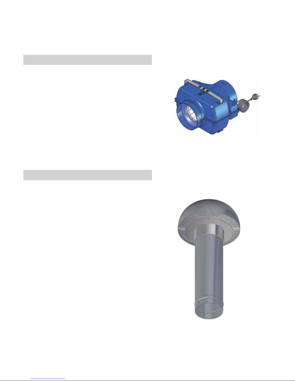
Option 1 - Inline Solution (Fig. 4a)
Models include IL-765 and IP-1140
Unit designed to be located in a roof space and then
duct to an external vent.
Included in the carton:
1. KLEENAIR Inline Motor Unit
2. Mounting Bracket
3. Fixing Screws
4. Hose Clips x4
5. 200mm FlexiDuct (5 Mtr Length)
6. Stainless Steel Eave Vent
Option 2 - External Solution (Fig. 4b)
Models include EL-765, EP-1140 and EPP-2010
Unit designed to be mounted externally either on an
external wall or penetrating through the roof.
Included in the carton:
1. KLEENAIR External Motor Unit
2. Hose Clips x2
3. 200mm FlexiDuct (5 Mtr Length)
Optional accessories when roof mounting:
1. 200mm Tile Roof Install Kit (HBX200TILE)
Includes roof dektite (ashing) for tile
roof and mounting brackets x2
2. 200mm Metal Roof Install Kit (HBX200MET)
Includes roof dektite (ashing) for metal
roof and mounting brackets x2
Fig. 4b
Fig. 4a
4
Page 5
Conditions of Use and Maintenance
This rangehood is a domestic appliance which has been manufactured and tested to comply with Australian
and New Zealand Standard AS/NZS 60335.2.31 and is designed to work under Australian and New Zealand
conditions. The hoods are designed to remove bi-products of cooking – heat, steam, grease and odour.
This appliance is intended for domestic application only. Any other usage is at the owner’s risk and could be
dangerous. The manufacturer cannot be held liable for damage resulting from incorrect or improper use or
operation. This unit is approved for electrical safety (N5761).
WHISPAIR reserves the right to change the specication without notice.
All WHISPAIR performance gures are based upon standards developed by the Haus Appliance Group, which
either comply or are in excess of the government regulated standards.
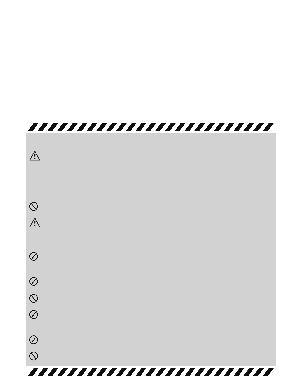
Safety
WARNING: The installation of WHISPAIR rangehoods must comply with the information in this guide.
Failure to install the rangehood in accordance with these installation instructions may result in
electrical hazards, injury, damage to your appliance and loss of warranty. Specically, failure by the
installer to install the screws or xing devices in accordance with these installation instructions may
result in electrical hazards. Please install the appliance as detailed in these instructions.
The rangehood is not intended for use by children or inrmed persons without supervision.
CAUTION: Accessible parts may become hot when used with cooking appliances. Please do not
touch halogen lighting whilst in use or for some time after switching off. The lamps operate at a high
temperature that may be harmful if contact is made.
Ensure the canopy rangehood is switched off before carrying out maintenance, to avoid any
possibility of electric shock.
Always use non-ammable materials to minimize the risk of re.
Do not ambé under the range hood.
There must be adequate ventilation of the room of operation when the range hood is used at the
same time as appliances burning gas or other fuels.
In the case of damage to power supply cords, use only an authorized service agent or licensed electrician.
Exhausted air must not be discharged into a chimney or ue.
5
Page 6
Ducting & Extraction Levels
WHISPAIR ducting is designed to ensure optimum performance for your rangehood. Please follow the installation
instructions carefully.
Every WHISPAIR rangehood must be ducted to the externally or cavity mounted KLEENAIR unit by the use of
non-ammable ducting. The rangehood must not be ducted into a wall cavity or a ceiling space where a build-up
of grease can occur and become a potential re risk. Ensure the external outlet on the KLEENAIR unit is not
covered and the air ow is not restricted in any way as this may result in reduced performance.
The duct must at all times have a cross sectional surface area equivalent to the hood outlet. The hood outlet has
a circular cross section of 200mm in diameter or an approximate area of 31,400mm. Do not reduce the duct
size at any time and avoid sharp bends. If the duct run is longer than six (6) metres, it may be necessary to
enlarge the duct size to ensure optimum performance. The manufacturer does not guarantee performance
when the duct length is greater than six (6) metres.
Ensure that all ducting is correctly tted and sealed with pipe clips, duct tape or silicone to ensure that fumes do
not escape prior to reaching the KLEENAIR unit.
The WHISPAIR extraction calculations are based upon a 50pa change of head of pressure loss and are used to
factor the variance of air ow resistance through the ducting. 50pa is equivalent to approximately 4 metres (the
recommended length) of exi ducting with one gentle bend, which is above and beyond the industry standard
of one straight metre of ducting. The KLEENAIR LITE offers a powerful 765 cubic meters per hour (213 litres per
second) of air movement. The KLEENAIR PRO offers 1140 cubic meters per hour (317 litres per second) whilst
for serious users the KLEENAIR PRO PLUS boasts a market leading 2010 cubic meters per hour (558 litres per second).
To Rangehood Unit
Gentle Bend
In Ducting
THE RECOMMENDED DUCT
LENGTH (INSTALLATION DISTANCE)
IS 4 METERS.
THE MINIMUM INSTALLATION
DISTANCE IS 3 METERS.
GENTLE BENDS IN THE DUCTING
ARE RECOMMENDED AS IT ASSISTS
IN MUFFLING NOISE FROM THE
EXTERNAL FAN UNIT.
6
Page 7

Noise Levels & Extraction Levels
All KLEENAIR units operate at maximum external sound pressure level between 43dB(A) and 76dB(A). The
internal operation of the systems will have a varying sound level dependent on the style of hood, the motor option
selected, the acoustics of the environment and the installation method used. It was established through testing,
in accordance with the Australian Standards, that the internal noise level varied between 33dB(A) and 65dB(A) on
the air movement settings available.
It is important to understand that whilst WHISPAIR rangehoods offer quieter operational noise levels due to the
positioning of the motor externally to the primary cooking environment, the noise levels as a consequence of air
movement or ‘wind’ noise are equivalent to other premium hoods in the Australian and New Zealand market
place, although it must be noted that the extraction levels are signicantly higher.
Servicing
The installation and tting of the rangehood should be done in such a way that will allow the unit to be
removed if service is required. Additional costs incurred in the removal, such as damage to walls, are not
covered under warranty.
It is expected that the stainless steel is cleaned with a quality non-abrasive stainless steel cleaner. The
bafe lters are removable and dishwasher safe. It is recommended that these items be cleaned regularly.
There is a re risk if cleaning is not carried out in accordance with the instructions.
The KLEENAIR unit should be checked regularly to ensure that nothing is obstructing the air ow from
the housing.
Extraction Level versus Noise Level
Cubic Meters / Hour of Air Movement
[m/hr]600 1200 1800
A.740 B.765 C.1140 D.2010
Sound Pressure Level
10
20
30
40
50
60
70
0
[dB]
Extraction Level Comparison
Cubic Meters / Hour of Air Movement
[m/hr]600 1200 1800
Change in Pressure
100
200
300
400
500
600
700
0
[Pa]
A. Standard premium rangehood found in the Aus/NZ market offering 740 m/hr
B. KleenAir Lite Unit offering 765 m/hr
C. KleenAir Pro Unit offering 1140 m/hr
D. KleenAir Pro Plus Unit offering 2010 m/hr
A.740 B.765 C.1140 D.2010
7
Page 8

Part 1: Hood Installation Guide
Integrated Hood
Models include W3M06S2, W3M09S2, W3MD09S2 and A3W12S2
Step 1:
To install into your overhead cupboard, several holes may need to be cut into shelves to enable the ducting to exit
the cavity. Ensure the hood is mounted as close to the centre of the cooking surface as possible. Fit a shelf 290mm
(Undermount 60 & 90) or 320mm (Undermount 90 Super Deep) or 332mm (Undermount 120) from the base of the cupboard.
NOTE: The height of the underside of the hood body must be a minimum of 600mm above an electric cooktop &
650mm above a gas cook top and a maximum height of 1200mm. If the instructions of the hob specify a greater
distance than the minimum detailed, this shall be the minimum height for installation. Building codes that
stipulate a minimum dimenstion may vary from state to state, please check with your local council prior to installation.
Step 2:
Cut out a central 202mm hole in the shelf for ducting, matching the holes position to that of the outlet on top of the
hood. Additional holes might need to be cut to feed the duct out to the roof cavity.
Step 3:
Refer to Part 2: Motor Installation Guide.
Step 4:
Place the hood in the cabinet in the level position ensuring that the controls and display will be visable when
standing in front of the unit.
Step 5:
Using the six (6) mounting holes, screw the hood into position.
Both of the side panels and the rear panel of the hood have two
mounting holes each.
Step 6:
Attach the male plug of the rangehood unit to mains power supply.
Note to Electricians: Standard 10 Amp General Power Outlet (GPO)
required. Position GPO as close to the hood unit as possible.
Installing the grease trap and your lters:
The integrated range of hoods utilise a removable grease trap that
is used to catch excess amounts of grease and condensate from
the bafe lters. This trap can be removed for cleaning. The trap
consists of a concave channel with xing points in the channel of
the trap.
The bafe lters will then sit within the channel, with the lter
vanes running downward.
WARNING
DIMENSIONS ARE ACCURATE AT THE TIME OF PRINTING BUT HAUS APPLIANCES RESERVES THE RIGHT
TO CHANGE SPECIFICATIONS WITHOUT NOTICE. FOR BUILDING PURPOSES THE UNIT SHOULD BE
PROVIDED TO THE CABINET MAKER / BUILDER / KITCHEN DESIGNER FOR EXACT MEASUREMENTS.
Outlet
Grease Trap
Mounting Holes
Bafe Filters
8
Page 9

Part 1: Hood Installation Guide
Wall Hung Canopy
Models include W5L09S2, W5S09S2, W5R09S2, W5P09S2, W5V09S2, W5B09S2, A5M09S2, A5C09S2 and A5N12S2
Step 1:
Measure the height of the hood from the base to the top of the mounting hooks.
NOTE: The height of the underside of the hood body must be a minimum of 600mm above an electric cooktop &
650mm above a gas cook top and a maximum height of 1200mm. If the instructions of the hob specify a greater
distance than the minimum detailed, this shall be the minimum height for installation. Building codes that
stipulate a minimum dimenstion may vary from state to state, please check with your local council prior to installation.
Step 2:
Using a spirit level mark a vertical centre line on the wall where the hood hooks need to be positioned. It is best to
centre the hood unit to the cook top below.
Step 3:
Mark a horizontal line on the wall for the mounting bracket position. Centre and mark the two (2) xing points to the
left and right of the centre line. Drill and plug holes with suitable sized wall plugs.
Step 4:
Fix the wall bracket with two (2) suitable screws into the wall at the positions marked in step 3 to allow the body
of the hood to be hung on the wall.
Step 5:
Hang the body of the hood on the wall using the bracket attached in step 4.
Identify and mark several screw holes located inside the hood. Remove the
hood from the wall and drill and plug holes with suitable sized wall plugs.
Step 6:
Replace the hood back on the wall
and secure the hood by xing the
additional screws inside the hood
housing.
Step 7:
Secure the hood rmly to the wall
by tightening the hood hooks.
Step 8:
Secure the chimney bracket to the wall.
Step 9:
Refer to Part 2: Motor Installation Guide.
Step 10:
Place the chimney on the hood and secure to the chimney bracket.
You may need to drill some new holes through the cover and bracket to secure the chimney cover.
Step 11:
Attach the male plug of the rangehood unit to mains power supply. Note to Electricians: Standard 10 Amp
General Power Outlet (GPO) required. Position GPO as close to the hood unit as possible.
WARNING
DIMENSIONS ARE ACCURATE AT THE TIME OF PRINTING BUT HAUS APPLIANCES RESERVES THE RIGHT
TO CHANGE SPECIFICATIONS WITHOUT NOTICE. FOR BUILDING PURPOSES THE UNIT SHOULD BE
PROVIDED TO THE CABINET MAKER / BUILDER / KITCHEN DESIGNER FOR EXACT MEASUREMENTS.
9
1
2
3
5
4
6
7
Page 10

Part 1: Hood Installation Guide
Island Hung Canopy
Models include W7S09S2, W7V09S2, W7B09S2 and A7N12S2
Step 1:
Using a weighted stringline (plumb line), determine the central position of hood on the ceiling. It is best to centre
the hood unit to the cook top below. Mark the position. Before making the cut out, check for obstructions like
electrical cables, etc.
NOTE: The height of the underside of the hood body must be a minimum of 600mm above an electric cooktop &
650mm above a gas cook top and a maximum height of 1200mm. If the instructions of the hob specify a greater
distance than the minimum detailed, this shall be the minimum height for installation. Building codes that
stipulate a minimum dimenstion may vary from state to state, please check with your local council prior to installation.
Step 3:
Mount supplied island bracket to supporting beams on
the ceiling.
Step 4:
Adjust and x the roof bracket to the desired length.
Step 5:
Secure the FlexiDuct down the inside of the roof bracket taking care not to constrict the duct.
Step 7:
Slide the stainless steel chimney covers up and secure
to the bracket. You may need to drill some new holes
through the cover and bracket to secure the chimney
cover depending on desired length. In order to avoid
streaking the steel during the installation process do
not remove the protective lm from the upper piece
until all pieces are in the correct position.
Step 8:
Attached the hood unit to the base of the bracket.
Step 9:
Attach the male plug of the rangehood unit to mains
power supply. Note to Electricians: Standard 10 Amp
General Power Outlet (GPO) required. Position GPO
as close to the hood unit as possible.
WARNING
DIMENSIONS ARE ACCURATE AT THE TIME OF PRINTING BUT HAUS APPLIANCES RESERVES THE RIGHT
TO CHANGE SPECIFICATIONS WITHOUT NOTICE. FOR BUILDING PURPOSES THE UNIT SHOULD BE
PROVIDED TO THE CABINET MAKER / BUILDER / KITCHEN DESIGNER FOR EXACT MEASUREMENTS.
10
Page 11

Part 2: Motor Installation Guide
Motor Unit Positioning and Solution Options
11
EXTERNAL KLEENAIR
MOTOR SOLUTION
Wall Mounted
Wall
Fan Power Supply
Attached to Internal Hood Unit
200mm Ducting
Attached to Internal Hood Unit Outlet
Gentle Bend In Ducting
Maintain 200mm Duct Diameter
Ducting Pulled Tight
Housing Mounts
(Optional Accessory)
Dektite to suit
Metal or Tile Roof
(Optional Accessory)
Fan Power Supply
Attached to Internal Hood Unit
200mm Ducting
Attached to Internal
Hood Unit Outlet
Ducting Pulled Tight
Gentle Bend In Ducting
Maintain 200mm Duct Diameter
EXTERNAL KLEENAIR
MOTOR SOLUTION
Roof Mounted
Roof
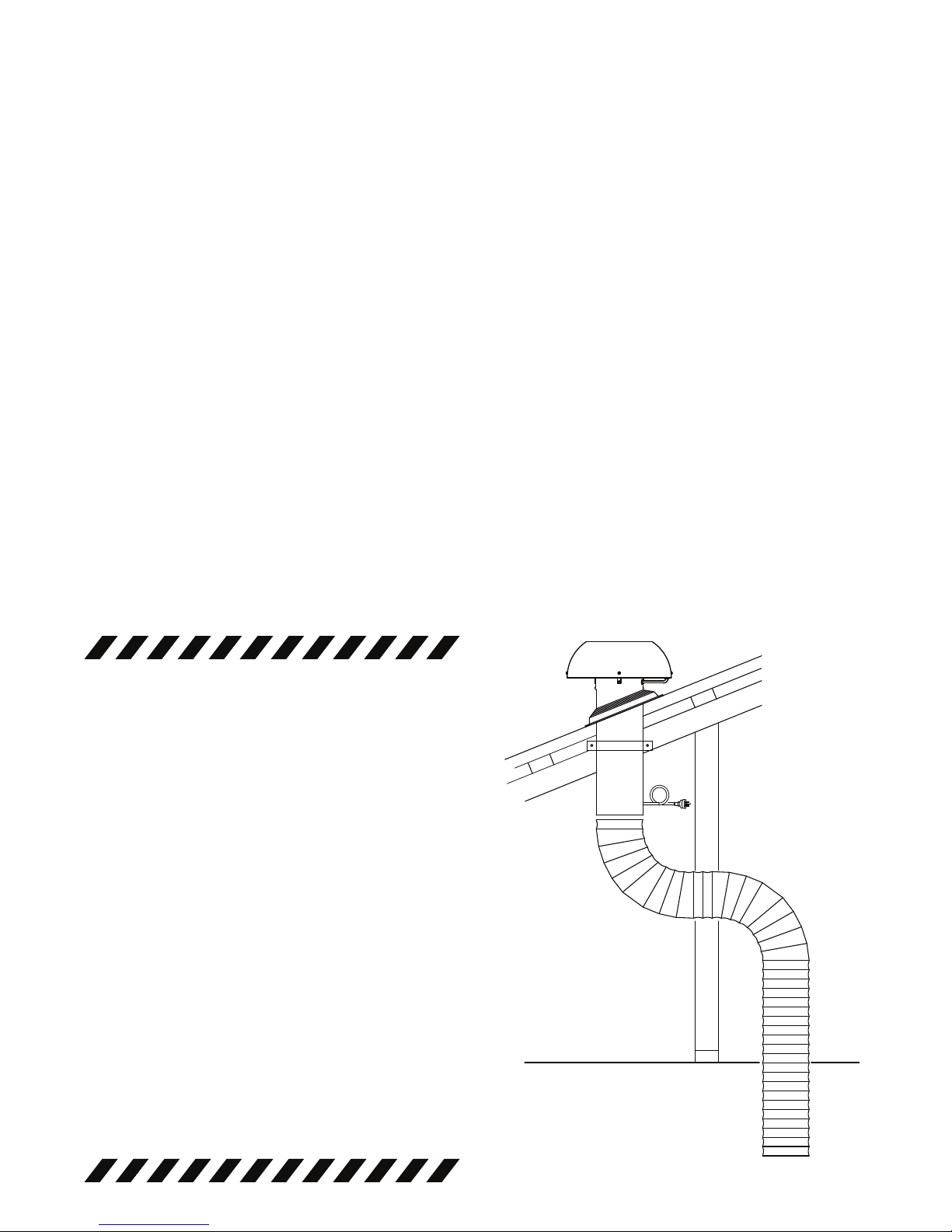
INLINE KLEENAIR
MOTOR SOLUTION
Wall Vented
Wall
Fan Power Supply
Attached to Internal Hood Unit
200mm Ducting
Attached to Internal
Hood Unit Outlet
Gentle Bend In Ducting
Maintain 200mm Duct Diameter
Ducting Pulled Tight
INLINE KLEENAIR
MOTOR SOLUTION
Eave Vented
Vent & Eave
Fan Power Supply
Attached to Internal Hood Unit
200mm Ducting
Attached to Internal Hood Unit Outlet
Gentle Bend In Ducting
Maintain 200mm Duct Diameter
Ducting Pulled Tight
Roof
Page 12

Mounting Bracket Outlet
Inlet
12
Part 2: Motor Installation Guide
Inline Solution
Positioning your KLEENAIR Unit:
It is recommended that the KLEENAIR INLINE unit be mounted in a
roof space or wall cavity. Please ensure that the KLEENAIR unit is
positioned in an environment that is free of other gases to enable
an efcient expulsion of the cooking bi-products and to ensure that
back draft of external gases doesn’t take place.
Please ensure the motor is positioned away from other exhausts
such as re place chimneys, gas ues, etc. The inline unit an be
mounted so that it ducts directly through the wall or eave.
Step 1:
Establish a suitable position in the roof or wall cavity for the KLEENAIR unit, ensuring that the distance between the
KLEENAIR unit and the outside vent is under 800mm. The KLEENAIR unit must be located a minimum of 3
metres from the hood unit.
Step 2:
Using the mounting bracket and screws, mount the KLEENAIR unit to a beam, truss or another appropriate structures in the roof or wall space. Ensure the direction of airow is toward the outside. The direction of air ow is
marked on the KLEENAIR unit.
Step 3:
Cut a 200mm diameter hole in the wall or eave to enable the mounting of the external vent. Please ensure that the
hole is cut in a practical position to enable the FlexiDuct to be secured. Attach the FlexiDuct to the vent and then
mount vent to the wall or eave.
Step 4:
Attach the FlexiDuct from the external vent to the outlet of the KLEENAIR unit using pipe clips. To minimise inefciencies and noise ensure the duct is pulled tight.
Step 5:
Attach FlexiDuct from the KLEENAIR unit to the rangehood using pipe clips. Ensure that the duct is pulled tightly
to ensure that FlexiDuct remains rm and stable during operation. Avoid sharp bends in the duct. Gentle bends in
the ducting are recommended as it assists in mufing noise from the fan unit back to the rangehood. If the
FlexiDuct needs to be extended attach the two FlexiDuct ends using a RigidDuct insert, secured by pipe clips or
duct tape.
Step 6:
Attach the male plug of the KLEENAIR unit to the female plug of the rangehood to enable power supply to the fan
motor unit. An extension lead (not supplied) of up to ve meters may be added if required.
Page 13

Mounting PointsOutlet
Rear View Front View
Mounting Bracket
13
Step 1:
Cut a 200mm diameter hole in the wall to enable the rigid duct on the back of the KLEENAIR unit to protrude.
Please ensure that the hole is cut in a practical position to enable the FlexiDuct to be secured.
Step 2:
Remove the mounting bracket from your KLEENAIR unit by twisting the cover
in an anti clockwise direction. Mark at least four mounting points on the wall
and pre-drill the holes required.
Step 3:
Attach the FlexiDuct to the rigid duct on the back of the mounting bracket
using the pipe clips supplied.
Step 4:
Fix the mounting bracket to the wall using the screws and wall plugs provided.
Step 5:
Feed power cable through the centre of the mounting bracket and return the KLEENAIR unit on to the mounting
bracket and x it by rotating the cover in a clockwise direction noting the locating points. Lock the cover into position by tightening the locking screw.
Step 5:
Attach FlexiDuct from the KLEENAIR unit to the rangehood using pipe clips. Ensure that the duct is pulled tightly
to ensure that FlexiDuct remains rm and stable during operation. Avoid sharp bends in the duct. Gentle bends in
the ducting are recommended as it assists in mufing noise from the fan unit back to the rangehood. If the
FlexiDuct needs to be extended attach the two FlexiDuct ends using a RigidDuct insert, secured by pipe clips or
duct tape.
Step 6:
Attach the male plug of the KLEENAIR unit to the female plug of the rangehood to enable power supply to the fan
motor unit. An extension lead (not supplied) of up to ve meters may be added if required.
Part 2: Motor Installation Guide
External Solution (Wall Mounted)
Positioning your KLEENAIR Unit:
It is recommended that when the KLEENAIR EXTERNAL UNIT is
WALL mounted, it is positioned a minimum 1800mm above the
ground surface with a downward clearance of 1200mm and with a
radial clearance of 600mm. Please ensure that the KLEENAIR unit
is positioned in an environment that is free of other gases to enable
an efcient expulsion of the cooking bi-products and to ensure that
back-draft of external gases doesn’t take place.
Please ensure the motor is positioned away from other exhausts
such as re place chimneys, gas ues, etc. The unit can be
mounted so that it ducts directly through the wall.
Inlet
Mounting Points
Mounting Bracket
Cover
Page 14

14
RigidDuct
Outlet
Inlet
Step 7:
Attach FlexiDuct from the KLEENAIR unit to the rangehood using pipe clips. Ensure that the duct is pulled tightly
to ensure that FlexiDuct remains rm and stable during operation. Avoid sharp bends in the duct. Gentle bends in
the ducting are recommended as it assists in mufing noise from the fan unit back to the rangehood. If the
FlexiDuct needs to be extended attach the two FlexiDuct ends using a RigidDuct insert, secured by pipe clips or
duct tape.
Step 8:
Attach the male plug of the KLEENAIR unit to the female plug of the rangehood to enable power supply to the fan
motor unit. An extension lead (not supplied) of up to ve meters may be added if required.
Part 2: Motor Installation Guide
External Solution (Roof Mounted)
Positioning your KLEENAIR Unit:
It is recommended that when the KLEENAIR EXTERNAL UNIT is
ROOF mounted, it is positioned a minimum 2100mm above the
ground surface with a radial clearance of 600mm. Please ensure that
the KLEENAIR unit is positioned in an environment that is free of
other gases to enable an efcient expulsion of the cooking
bi-products and to ensure that back-draft of external gases doesn’t
take place.
Please ensure the motor is positioned away from other exhausts
such as re place chimneys, gas ues, etc. The unit can be mounted
so that it ducts directly through the roof.
Step 1:
Cut a 200mm diameter hole in the roof to enable the RigidDuct on
the base of the KLEENAIR unit to protrude down into the roof space.
Afx the dektite (optional accessory) to the roof surface. Please
ensure that the hole is cut in a practical position to enable the FlexiDuct to be secured.
Step 2:
Using standard 200mm pipe mounts (optional accessory), mount
the RigidDuct neck to beams, trusses or other appropriate structures in the roof space. Ensure the RigidDuct protrudes past the top
of the dektite by at least 75mm.
Step 3:
Remove the mounting bracket from your KLEENAIR unit by rotating
the cover in an anti clockwise direction.
Step 4:
Fix the mounting bracket to the RigidDuct using the screws
provided.
Step 5:
Feed power cable through the centre of the mounting bracket and
return the KLEENAIR unit on to the mounting bracket and x it by
rotating the cover in a clockwise direction. Lock the cover into position by tighting the locking screw.
Step 6:
Attach the FlexiDuct to the RigidDuct using the pipe clips supplied.
min 75mm
Mounting Points
Mounting Bracket
Mounting
Bracket
Page 15

Operation
Operating your control panel with the 4 Button Control:
Turning the extraction function ON or OFF:
In standby mode, press button 1 to turn on operating mode, then press button 1 or 2 to change the speed.
The hood has three speed options and a boost speed plus the off function.
To turn hood off, press button 2 repeatedly until hood returns to standby mode.
Auto off function: After 1 hour of operation without alteration, the fan motor will turn off (returned to standby)
Turning the light function ON or OFF:
Press button 3 to turn on or turn off the light independently in standby mode. Light will automatically shut off
when time elapses in timer mode.
Turning the timer function ON or OFF:
In operating mode, press button 4 to engage the timer function, then press button 1 or 2 to adjust the delay time.
The default time set is 10min and can be increased in increments of 10min up to 1 hour.
For the controller without the LCD, the LED positioned behind button 4 will periodically blink quickly to indicate the
delayed time remaining. i.e. For 30min remaining the LED will blink 3 times quickly. When the timer function is
engaged the (timer) LED positioned behind button 4 will blink slowly.
Adjusting the clock function (Control with LCD Only):
In standby mode, press button 4 for two seconds to enter time-adjust mode, press button 1 or 2 to adjust the
hour, press button 4 again, then press button 1 or 2 to adjust the minute. Time will be automatically saved as
default if not adjusted after 5 seconds.
15
BOOST
-
+
Page 16

Product Care
It is recommended that your WHISPAIR rangehood and all of its items be cleaned regularly.
Before any cleaning or maintenance work, disconnect the cooker hood from the mains power supply.
Cleaning the stainless steel hood unit
It is expected that the stainless steel is cleaned with a quality non-abrasive stainless steel cleaner.
Use a soft cloth for application.
Cleaning the KLEENAIR Fan Motor Unit
The KLEENAIR unit should be checked regularly to ensure that nothing is obstructing the air ow from
the housing.
If there are obstructions, please remove the debris ensuring the product returns to the manufacturer’s
intended operating condition.
Cleaning the bafe lters
The bafe lters and grease trap can be removed by sliding them from their mounted position within the hood and
washed in the dishwasher or by hand.
Use hot water and liquid detergent.
After cleaning, leave the lters and trap to dry before placing back in the hood.
Changing the lamp
WARNING: Please be aware that whilst in use both LED and halogen lighting units will become very hot and will
remain hot for some time after switching off. Please allow the lamp area to cool before operating near the lamps.
For Halogen: To access the halogen lamp, push the inner cover of the lamp up (1). The cover will click and can
be pulled down. Remove the old halogen globe out of the connection socket (2) and replace it with a new 20W
globe (3). Push the cover back up and ensure it is secured into place.
For LED: Disconnect from with inside the hood unit. Push the entire LED unit down from with inside the hood (4).
Replace with a new unit and reconnect power supply. Please replace only with a genuine unit.
Remove cover to access
halogen globe Remove halogen globe unit
16
Remove LED unit
Page 17

Warranty
Every WHISPAIR rangehood comes with a 3-Year parts and labour warranty.
All WHISPAIR KLEENAIR units come with a 10-Year replacement product warranty. This is a change over warranty.
The consumer is responsible for any charges associated with removal of the faulty unit and installation of the new unit.
The customer may also be responsible for any freight charges incurred in this change over process.
The installation of WHISPAIR rangehoods must comply with the information in the guide. Failure to follow the
guideline may result in loss of warranty.
We recommend our customers use an authorised WHISPAIR installer.
Any imperfections in the nishes or in the natural materials used should not be considered as faults but a typical
characterisitc of these crafted products.
Should you ever need to make a warranty related enquiry about your WHISPAIR product, in Australia simply call
+61 (0)3 9700 9100 or in New Zealand call +64 (0)9 964 0400 to speak with our friendly customer service
consultants. We suggest you have the following information close at hand to make the process as easy as possible:
1. Model number of your rangehood
2. A copy of your WHISPAIR pro forma invoice
3. Address details of where the appliance has been installed
Any associated or ancillary costs to be incurred by you as a result of replacement or repair of your WHISPAIR
rangehood under this guarantee shall, in all cases, be previously approved by PR Kitchen & Washroom Systems Pty Ltd.
Please note: The benets provided under this warranty are additional to other rights and remedies available to
the customer under the Australian Customer Law.
Your Statutory Rights
Our goods come with guarantees that cannot be excluded under the Australian Consumer Law. You are entitled
to a replacement or a refund for a major failure and for compensation for any other reasonably foreseeable loss
or damage. You are also entitled to have the goods repaired or replaced if the goods fail to be of acceptable
quality and the failure does not amount to a major failure.
17
Page 18

Notes
_______________________________________________________________________________________________
_______________________________________________________________________________________________
_______________________________________________________________________________________________
_______________________________________________________________________________________________
_______________________________________________________________________________________________
_______________________________________________________________________________________________
_______________________________________________________________________________________________
_______________________________________________________________________________________________
_______________________________________________________________________________________________
_______________________________________________________________________________________________
_______________________________________________________________________________________________
_______________________________________________________________________________________________
_______________________________________________________________________________________________
_______________________________________________________________________________________________
_______________________________________________________________________________________________
_______________________________________________________________________________________________
_______________________________________________________________________________________________
_______________________________________________________________________________________________
_______________________________________________________________________________________________
_______________________________________________________________________________________________
18
Page 19

Notes
_______________________________________________________________________________________________
_______________________________________________________________________________________________
_______________________________________________________________________________________________
_______________________________________________________________________________________________
_______________________________________________________________________________________________
_______________________________________________________________________________________________
_______________________________________________________________________________________________
_______________________________________________________________________________________________
_______________________________________________________________________________________________
_______________________________________________________________________________________________
_______________________________________________________________________________________________
_______________________________________________________________________________________________
_______________________________________________________________________________________________
_______________________________________________________________________________________________
_______________________________________________________________________________________________
_______________________________________________________________________________________________
_______________________________________________________________________________________________
_______________________________________________________________________________________________
_______________________________________________________________________________________________
_______________________________________________________________________________________________
19
Page 20

PR Kitchen & Washrooms Systems Pty Ltd
83 Bangholme Road, Dandenong South
Victoria Australia 3175
Australian Sales & Service:
T +61 (0)3 9700 9100
E info@whispair.com.au
www.whispair.com.au
New Zealand Sales & Service:
T +64 (0)9 964 0400
E info@whispair.co.nz
www.whispair.co.nz
Terms & Conditions
Due to ongoing research and develoment, th
reserves the right to change specifications without
notice. If specifications are critical to end use,
please ask your local retail agent. This information is provided without prejudice to the standard
terms and conditions of the sale of the manufacturer. This installation guide supersedes all previous installation guide. All due care has been
taken while compiling this installation guide at the
time of print, however no responsibility is taken
for error. Issued October 2013.
 Loading...