

Whirlwind
W1 39 Pin Connector System Technical Data
Materials and Finishes:
• Contacts: Copper alloy,
hard gold plate over
nickel under plate per
MIL-G-45204
• Insulators: Low temperature
elastomer
• ‘O’ Rings and Seals;
Low temperature elastomer
• Shells and Dust Caps:
All aluminum alloy, black
anodized coating
Chain-Stainless steel
Mechanical Data:
• Operating Temperature:
-40“C to +105°C
-40°Fto+22rF
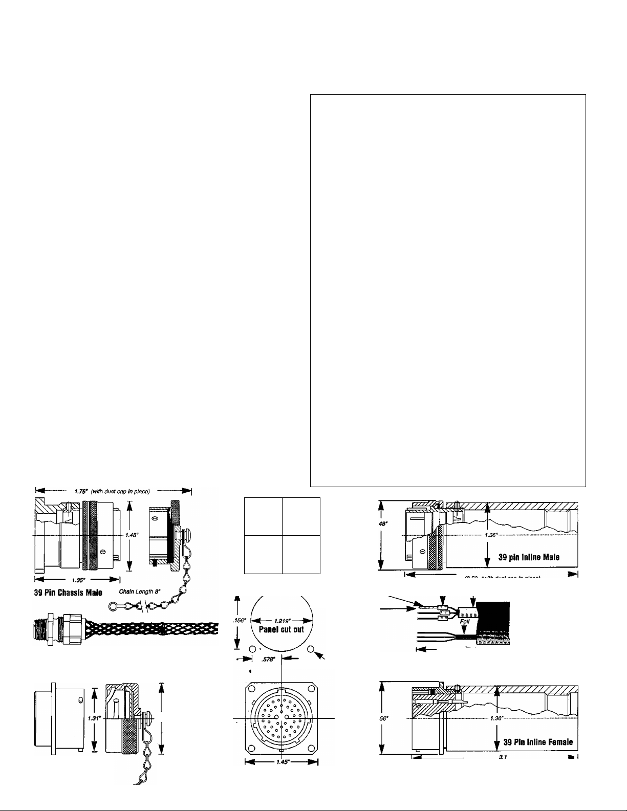
The Whirlwind Wl is a 39 contact, quick disconnect connector
system based on the proven MIL-26482 multipin standard. The pin
and socket modules are shell size 20 with a standard 39 contact
insert arrangement. The solder style contacts are permanently
mounted in resilient rubber insulators to provide years of trouble
free service. Whirlwind manufactures a robust aluminum backshell
to protect the soldered connections and provides a waterproof
mesh grip for an absolutely reliable strain relief on the c|ble.
The Wl system utilizes a 39 pin male insert in a plug shell, with
a quarter-turn locking ring and a 39 socket female insert in a
receptacle shell with studs, that mates with the male plug shell.
Whirlwind provides the W1 in four standard configurations, male
and female inline and male and female chassis mount. The Wl can
be used to interconnect up to 12 balanced, shielded signal lines.
• Contacts: #20 AWG Solder
type (7.5 Amp rating)
• Contact Retention:
15 lbs. minimum
• Connector Engagement
and Separation Forces:
32 in. lbs. maximum
• Polarization: 5 Keyways
Electrical Data:
• Operating Voltage; 850
VDC or 600 VAC rmb
maximum
• Insulation Resistance;
5000 megohm minimum
• Contact Resistance;
6 milliohms maximum
W1CF
AB39FP
AB39CAP
PT1-16BK-1.5
PT3-16BK-1.0
PTM6BK-0.5
Wl Pin Out
W1CM
AB39MI
AB39MPA
AB39CAPWT Dust Cap with Studs For Male 39 Pin
PT1-16BK-1.5
PT3-16BK-1.0
PT1-16BK-0.5
Wl Pin Out
W1IF
AB39FI
AB39CAP
AB39H
AB60G
ABKR
PT1-16BK-1.1
PT3-16BK-0.5
PT1-16BK-0.5
W1 Pin Out
W1IM
AB39MI
AB39CAPWT
AB39H
AB60G
ABKR
PT1-16BK-1.1
PT3-16BK-0.5
PT1-16BK-0.5
Wl Pin Out
Female Panel Connector / Cap, Wiring Kit Complete
39 Pin Female Panel Mount Body with Studs
Dust Cap with Ring For Female 39 Pin
Drain Wire Insulator 1/16” BIk Shrink Tube 1.5” 13
Mylar / Foil Insulator 3/16” BIk Shrink Tube 1.0”
Solder Cup Insulator 1/16” BIk Shrink Tube 0.5"
Wiring Diagram For 39 Pin
Male Panel Connector / Cap, Wiring Kit Complete
39 Pin Male Inline Body with Ring
Panel Mount 39 Pin BIk Flange with Set Screw
Drain Wire Insulator 1/16” BIk Shrink Tube 1.5”
Mylar / Foil Insulator 3/16” BIk Shrink Tube 1.0”
Solder Cup Insulator 1/16” BIk Shrink Tube 0.5”
Wiring Diagram For 39 Pin
Female Inline Connector / Cap, Wiring Kit Complete
39 Pin Female Inline Body with Studs
Dust Cap with Ring For Female 39 Pin
39 Pin inline Housing with Set Screws
39-61 Inline Strain Relief Grip Range .375”-.50”
16mm Split Ring For Dust Cap Chain
Drain Wire Insulator 1/16” BIk Shrink Tube 1.1”
Mylar / Foil Insulator 3/16” BIk Shrink Tube 0.5”
Solder Cup Insulator 1/16” BIk Shrink Tube 0.5”
Wiring Diagram For 39 Pin
Male Inline Connector / Cap, Wiring Kit Complete
39 Pin Male Inline Body with Ring
Dust Cap with Studs For Male 39 Pin
39 Pin Inline Housing with Set Screws
39-61 Inline Strain Relief Grip Range .375"-.50"
16mm Split Ring For Dust Cap Chain
Drain Wire Insulator 1/16” BIk Shrink Tube 1.1”
Mylar / Foil Insulator 3/16” BIk Shrink Tube 0.5”
Solder Cup Insulator 1/16” BIk Shrink Tube 0.5”
Wiring Diagram For 39 Pin
1
1
13
39
1
1
1
1
13
13
39
1
1
1
1
1
1
13
13
39
1
1
1
1
1
1
13
13
39
1
(Strain relief Bushing adds approximately 2’ to rear of oonnector)
1.20’ (with dust cap In place)
1.46’
(Chassis connectors
39 Pin Chassis Female
mount on front of panel)
io^
//{/// o *
Hi n ^ o <
If 1 If ^ ^ <
ll 1 1 ° ® ^
39 Pin Chassis Male
O f,
o ^ ^ \ Yt
0 0 \\ \ \\
a o o |] I ]
o ® ® jf^i a
0 o j) j a
(3.53’ (with dust cap In place)
Q i Q Dmin wire insulator Solriar cup insulator Foil insulator
2.0’
(2.5’ for panel mount)
(3.S3’ with dust cep in place)
39 Pin Chassis Female
—■ 0 .147" for 110 screw
0 .172’for *S screw
3.r
3.1"
------
CaUe
l¥marfltloii
durnm
--------
lü»
39 Pin
56 Pair Coior Code
XLR Pin3
Pair# {-)
1 Black
2 Black White
3 Black Green
4 Black Blue
Black Yellow
5
6 Black Brown
7 Black Orange
8 Red White
9 Red Green
Red Blue
10
11 Red Yellow
12
Red
13 Red Orange
14 Green White
Green Blue
15
Green Yellow
16
17 Green
18 Green Orange
19 White
20 White Yellow
21 White Brown
22
White
23 Blue
24 Blue Brown
25 Blue Orange
Brown Yellow
26
27 Brown Orange
28 Orange Yellow
29 Purple Orange
30 Purple Red
31 Purple White
32 Purple Green
Purple
33
34
Purple
35 Purple
36 Purple Black
37 Gray White
38 Gray
39 Gray Red
40 Gray Green
41 Gray Orange
42 Gray Yellow
43 Gray Black
44 Gray Blue
Pink
45
Pink Green
46
47 Pink
48 Pink Yellow
Pink Brown
49
Pink
50
51 Pink Purple
52 Pink Gray
53 Beige White
54
Beige
55 Beige Blue
56 Beige Yellow
Pin 2 Pin1
(+) (g)
Red
Brown
Brown
Blue
Orange
Yellow
Blue
Yellow
Brown
Brown
White
Blue
Orange
Green
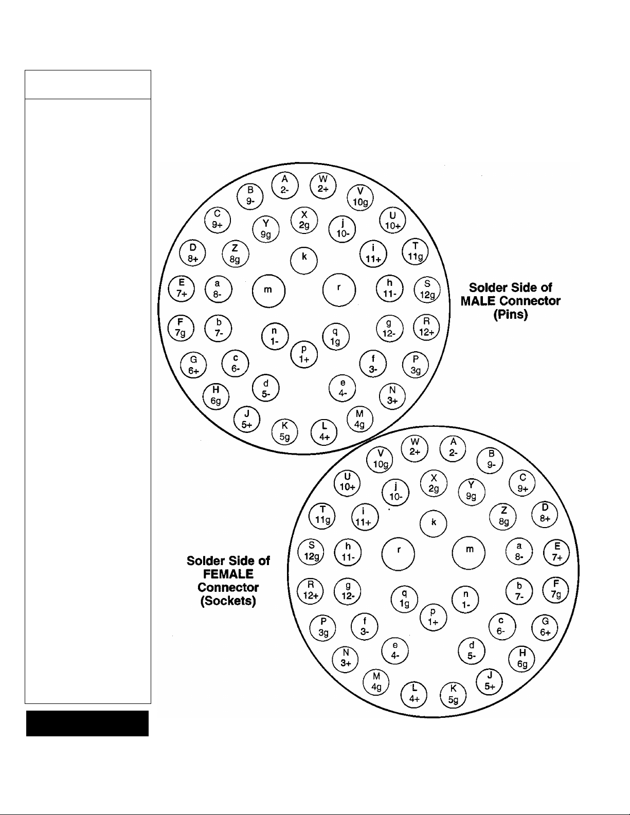
Whirlwind W1 89 Pin Connector
Male And Female Wiring Code
1. Use these drawings for wiring 39 contact connectors both Male (Pins) and Female (Sockets).
2. The standard Whirlwind layout begins at the stage box. Chassis mount Female connectors
with studs are the first choice for panel or box mounting. Inline Males with locking rings are the
first choice for cable connectors.
3. Systems using connectors of this series require only that a Male connector with ring plugs
into a Female connector with studs.
whirlwind
PO Box 12692 Rochester,
New York 14612
(716) 663-8820
Drawing can be used for mating face of opposite sex connector
Effective 11/93
 Loading...