

Whirlpool YLTE5243DQ8/Dryer Parts Diagram
24" (61 CM) ELECTRIC WASHER/DRYER
INSTALLATION INSTRUCTIONS
INSTRUCTIONS POUR L’INSTALLATION DE LA
LAVEUSE/SÉCHEUSE ÉLECTRIQUE DE 24" (61 CM)
Table of Contents / Table des matières
WASHER/DRYER SAFETY.............................. 1
INSTALLATION INSTRUCTIONS.................... 2
Tools and Parts............................................. 2
Alternate Parts............................................... 2
Location Requirements................................. 3
Drain System................................................. 4
Electrical Requirements................................ 4
Venting Requirements................................... 5
Install Leveling Legs...................................... 6
Remove Foam
Connect Drain Hose...................................... 6
Connect Inlet Hoses...................................... 7
Secure Drain Hose........................................ 8
Plan Vent System.......................................... 8
Install Vent System...................................... 10
Level Washer/Dryer..................................... 10
Connect Vent............................................... 10
Complete Installation .................................. 10
Packing................................. 6
SÉCURITÉ DE LA LAVEUSE/SÉCHEUSE ......... 11
INSTRUCTIONS D’INSTALLATION.................... 12
Outillage et pièces ............................................ 12
Autres pièces .................................................... 13
Exigences d’emplacement .............................. 13
Système de vidange ......
Spécifications électriques................................. 15
Exigences concernant l’évacuation.................. 16
Installation des pieds de nivellement................ 17
Enlever l’emballage en mousse........................ 17
Raccordement du tuyau de vidange................ 17
Raccordement des tuyaux d’alimentation ....... 18
Immobilisation du tuyau de vidange................. 19
Planification du système d’évacuation............. 19
Installation du système d’évacuation............... 21
Nivellement de la laveuse/sécheuse ................ 21
Raccordement du conduit d’évacuation.......... 21
Achever l’installation...................................
................................... 14
...... 21
WASHER/DRYER SAFETY
Your safety and the safety of others are very important.
We have provided many important safety messages in this manual and on your appliance. Always read and obey all safety
messages.
This is the safety alert symbol.
This symbol alerts you to potential hazards that can kill or hurt you and others.
All safety messages will follow the safety alert symbol and either the word “DANGER” or “WARNING.”
These words mean:
You can be killed or seriously injured if you don't immediately
DANGER
WARNING
All safety messages will tell you what the potential hazard is, tell you how to reduce the chance of injury, and tell you what can
happen if the instructions are not followed.
follow instructions.
You
can be killed or seriously injured if you don't
instructions.
follow
W10222389A
INSTALLATION INSTRUCTIONS
Tools and Parts
Gather the required tools and parts before starting installation. Read
and follow the instructions provided with any tools listed here.
Parts needed for washer (not provided):
Inlet hoses Flat washers
To order:
Call the dealer from whom you purchased your washer/dryer.
Call the toll-free number listed on the cover of the Washer/
Dryer User Instructions.
Visit the website listed on the cover of the Washer/Dryer
User Instructions.
NOTE: Replace inlet hoses after 5 years of use to reduce the risk
of hose failure. Record hose installation or replacement dates for
future reference.
Tools needed:
#2 Phillips and flat-blade
screwdriver
Adjustable wrench that
opens to 1" (25 mm) or
9
" open-end wrench
⁄16
(for adjusting washer/dryer
feet)
¼" nut driver or socket
wrench
Tin snips (for new vent
installations)
Parts supplied:
Remove parts package from the washer basket. Check that all
parts were included.
Caulking gun and
compound (for installing
new exhaust vent)
Level
Knife
Vent clamps
Pliers
Scissors
Wood block (for leveling)
Ruler or measuring tape
Parts needed:
Check local codes. Check existing electrical supply and venting,
and see “Electrical Requirements” and “Venting Requirements”
before purchasing parts.
Mobile home installations require metal exhaust system hardware
available for purchase from the dealer from whom you purchased
your washer/dryer. For further information, please reference the
“Assistance or Service” section of the Washer/Dryer User
Instructions.
Alternate Parts
Your installation may require additional parts. For information on
ordering, please refer to the toll free phone numbers on the front
page of the Washer/Dryer User Instructions.
If You Have You Will Need to Buy
Laundry tub or
standpipe taller than
96" (2.4 m)
1" (25 mm) diameter
standpipe
Overhead sewer Standard 20 gal. (76 L) 34" (864 mm)
Floor drain Siphon break, Part Number 285320,
Sump pump system (if not already
available)
2" (51 mm) diameter to 1" (25 mm)
diameter standpipe adapter, Part
Number 3363920
tall drain tub or utility sink and sump
pump (available from local plumbing
suppliers)
additional drain hose, Part Number
285702 and connector kit,
Part Number 285442
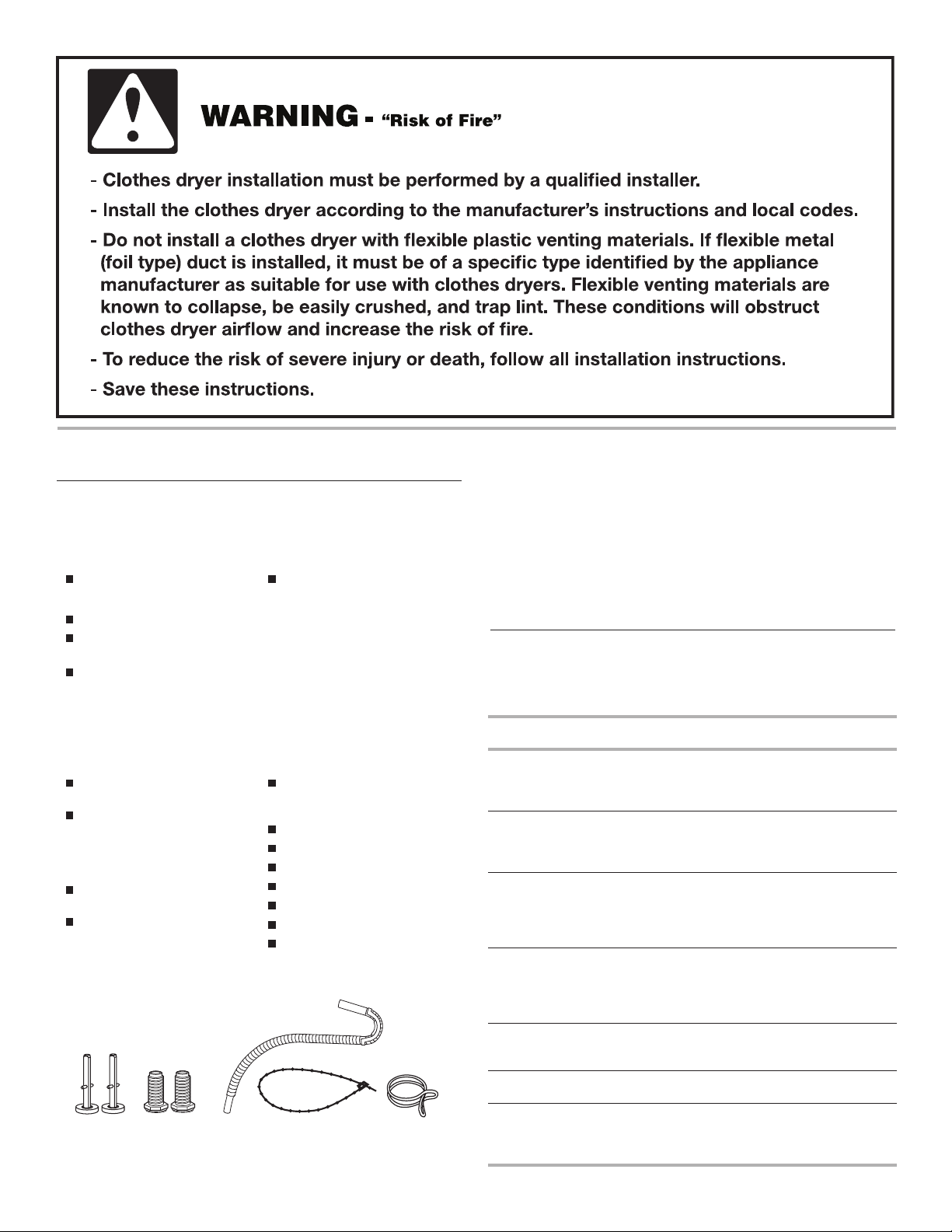
A B C D E
A. Rear leveling legs (2)
B. Front leveling legs (2)
C. Drain hose
D. Plastic strap
E. Silver double-wire hose clamp
2
Drain hose too
Lint clogged drain Drain protector, Part Number 367031
Water faucets
beyond reach of fill
hoses
short Drain hose, Part Number 285664 and
connector kit, Part Number 285442
2 longer water fill hoses:
6 ft (1.8 m) Part Number 76314,
10 ft (3.0 m) Part Number 350008
WARNING
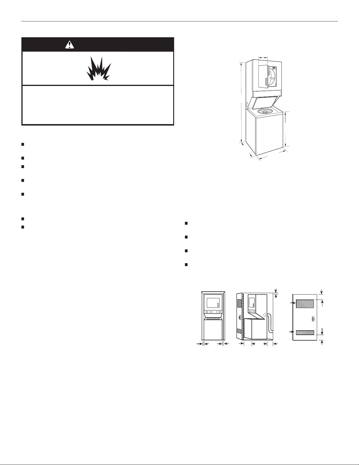
Location Requirements
Washer/Dryer Dimensions
3
⁄8
15 "
(391 mm)
Explosion Hazard
Keep flammable materials and vapors, such as
gasoline, away from dryer.
Failure to do so can result in death, explosion, or fire.
You will need
A location that allows for proper exhaust installation. See
“Venting Requirements.”
A separate 30-amp circuit.
A grounded electrical outlet located within 2 ft (610 mm) of
either side of the washer/dryer. See “Electrical Requirements.”
A sturdy floor to support the washer/dryer weight (washer/
dryer, water, and load) of 500 lbs (226.8 kg).
A level floor with a maximum slope of 1" (25 mm) under entire
washer/dryer. Clothes may not tumble properly and automatic
sensor cycles may not operate correctly if washer/dryer is not
level. Installing on carpet is not recommended.
A water heater set to deliver 120°F (49°C) water to the washer.
Hot and cold water faucets located within 4 ft (1.2 m) of the
hot and cold water fill valves, and water pressure of 5-100 psi
(34.5-689.6 kPa).
The washer/dryer must not be installed or stored in an area where
it will be exposed to water and/or weather.
Do not operate your washer in temperatures at or below
32ºF (0ºC). Some water can remain in the washer and can cause
damage in low temperatures. See “Washer/Dryer Care” in the
Washer/Dryer User Instructions for winterizing information.
Do not operate your
lower temperatures, the dryer might not shut off at the end of an
automatic cycle. This can result in longer drying times.
Check code requirements. Some codes limit, or do not permit,
installation of the washer/dryer in garages, closets, mobile homes,
or sleeping quarters. Contact your local building inspector.
dryer at temperatures below 45°F (7°C). At
71 ¾"
(1822 mm)
1
⁄8
32 "
(816 mm)
*27 ¼"
(692 mm)
7
⁄8
23 "
(606 mm)
*Most installations require a minimum 5" (127 mm) clearance
behind the
dryer for the exhaust vent with elbow. See “Venting
Requirements.”
Installation spacing for recessed area or closet installation
The following spacing dimensions are recommended for this
washer/dryer. This washer/dryer has been tested for spacing of 0"
(0 mm) clearance on the sides, rear, and top. Recommended
spacing should be considered for the following reasons:
Additional spacing should be considered for ease of
installation and servicing.
Additional clearances might be required for wall, door,
and floor moldings.
Additional spacing on all sides of the washer/dryer is
recommended to reduce noise transfer.
For closet installation, with a door, minimum ventilation
openings in the top and bottom of the door are required.
Louvered doors with equivalent ventilation openings are
acceptable.
1"
(25 mm)
2
48 in.
(310 cm2)
3" (76 mm)
Installation Clearances
The location must be large enough to fully allow the dryer door
to open fully.
2
24 in.
"
1
(25 mm)
7
23 "
⁄8
(606 mm)
1
"
(25 mm)
1"*
(25 mm)
27¼"
(692 mm)
(155 cm2)
5"**
(127 mm)
3" (76 mm)
A B C
A. Recessed area
B. Side view - closet or confined area
C. Closet door with vents
*Required spacing
**Rear clearance may be 0" (0 mm) when house exhaust system
is lined up directly with dryer exhaust.
3
Mobile Home - Additional Installation Requirements
This washer/dryer is suitable for mobile home installations.
The installation must conform to the Canadian Manufactured
Home Standard, CAN/CSA-Z240 MH.
Mobile home installations require:
Metal exhaust system hardware, which is available for
purchase from your dealer.
Special provisions must be made in mobile homes to
introduce outside air into the dryer. The opening (such as a
nearby window) should be at least twice as large as the dryer
exhaust opening.
Electrical Requirements
WARNING
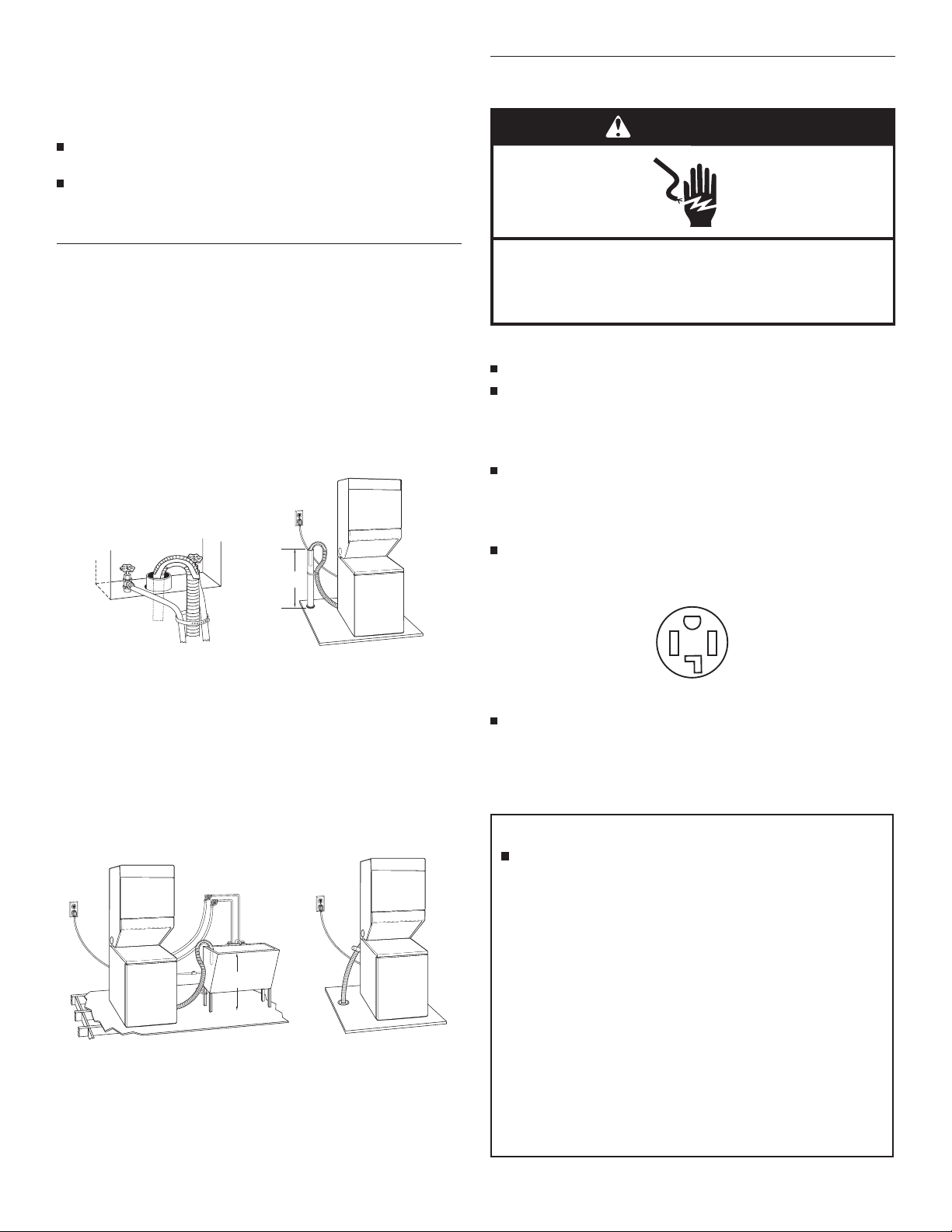
Drain System
The washer/dryer can be installed using the standpipe drain
system (floor or wall), the laundry tub drain system, or the floor
drain system. Select the drain hose installation method you need.
See “Alternate Parts.”
Standpipe drain system - wall or floor (views A & B)
The standpipe drain requires a minimum diameter standpipe of
2" (51 mm). The minimum carry-away capacity can be no less than
17 gal. (64 L) per minute. A 2" (51 mm) diameter to 1" (25 mm)
diameter standpipe adapter kit is available. See “Alternate Parts.”
The top of the standpipe must be at least 39" (991 mm) high and
no higher tha
Laundry tub drain system (view C)
The laundry tub needs a minimum 20 gal. (76 L) capacity. The top
of the laundry tub must be at least 34" (864 mm) above the floor
and no higher than 96" (2.4 m) from the bottom of the washer.
Floor drain system (view D)
The floor drain system requires a siphon break that may be
purchased separately. See “Alternate Parts.”
The siphon break must be a minimum of 28" (711 mm) from the
bottom of th
n 96" (2.4 m) from the bottom of the washer.
39"
(991 mm)
A
e washer. Additional hoses might be needed.
34"
(864 mm)
B
Electrical Shock Hazard
Plug into a grounded 4 prong outlet.
Failure to do so can result in death or electrical shock.
It is your responsibility
To contact a qualified electrical installer.
To be sure that the electrical connection is adequate and in
conformance with the Canadian Electrical Code, C22.1-latest
edition and local codes. A copy of the above codes standard
may be obtained from: Canadian Standards Association, 178
Rexdale Blvd., Toronto, ON M9W 1R3 CANADA.
To supply the required 4 wire, single phase, 120/240 volt,
60 Hz., AC only electrical supply on a separate 30-amp circuit,
fused on both sides of the line. A time-delay fuse or circuit
breaker is recommended. Connect to an individual branch
circuit.
This dryer is equipped with a CSA International Certified
Power Cord intended to be plugged into a standard 14-30R
wall receptacle. The cord is 5 ft (1.52 m) in length. Be sure wall
receptacle is within reach of dryer’s final location.
4-wire receptacle 14-30R
Do not use an extension cord.
If you are using a replacement power supply cord, it is
recommended that you use Power Supply Cord Replacement
Part Number 9831317. For further information, please reference
the service numbers located in the Washer/Dryer User
Instructions.
GROUNDING INSTRUCTIONS
For a grounded, cord-connected washer/dryer:
This washer/dryer must be grounded. In the event of
malfunction or breakdown, grounding will reduce the risk of
electric shock by providing a path of least resistance for
electric current. This washer/dryer is equipped with a cord
having an equipment-grounding conductor and a grounding
plug. The plug must be plugged into an appropriate outlet
that is properly installed and grounded in accordance with
all local codes and ordinances.
WARNING: Improper connection of the equipment-
grounding conductor can result in a risk of electric shock.
C
D
4
Check with a qualified electrician or service representative or
personnel if you are in doubt as to whether the washer/dryer
is properly grounded. Do not modify the plug provided with
the washer/dryer: if it will not fit the outlet, have a proper
outlet installed by a qualified electrician.
SAVE THESE INSTRUCTIONS
Venting Requirements
WARNING
Fire Hazard
Use a heavy metal vent.
Do not use a plastic vent.
Do not use a metal foil vent.
Failure to follow these instructions can result in death
or fire.
WARNING: To reduce the risk of fire, this washer/dryer
MUST BE EXHAUSTED OUTDOORS.
IMPORTANT: Observe all governing codes and ordinances.
The dryer exhaust must not be connected into any gas vent,
chimney, wall, ceiling, attic, crawlspace, or a concealed space
of a building.
If using an existing vent system
Rigid metal vent
For best drying performance, rigid metal vents are
recommended.
Rigid metal vent is recommended to avoid crushing and
kinking.
Flexible metal vent
Flexible metal vents are acceptable only if accessible for
cleaning.
Flexible metal vent must be fully extended and supported
when the dryer is in its final location.
Remove excess flexible metal vent to avoid sagging and
kinking that may result in reduced airflow and poor
performance.
Do not install flexible metal vent in enclosed walls, ceilings,
or floors.
The total length of flexible metal vent should not exceed
3
⁄4 ft (2.4 m).
7
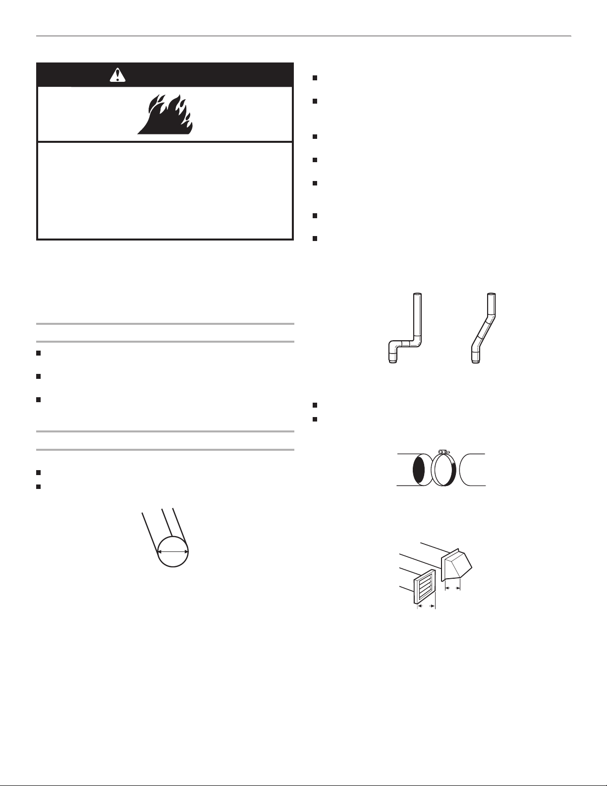
Elbows
45° elbows provide better airflow than 90° elbows.
Clean lint from the entire length of the system and make sure
exhaust hood is not plugged with lint.
Replace any plastic or metal foil vent with rigid or flexible
heavy metal vent.
Review Vent system chart. Modify existing vent system if
necessary to achieve the best drying performance. Only rigid
or flexible metal vent shall be used for exhausting.
If this is a new vent system
Vent material
Use a heavy metal vent. Do not use plastic or metal foil vent.
4" (102 mm) heavy metal exhaust vent and clamps must be
used. DURASAFE™ venting products are recommended.
4"
102 mm
4" (102 mm) heavy metal exhaust vent
DURASAFE™ vent products can be purchased from your
dealer or by calling Whirlpool Parts and Accessories. For more
information, see the “Assistance or Service” section of the
Washer/Dryer User Instructions.
Good Better
Clamps
Use clamps to seal all joints.
Exhaust vent must not be connected or secured with screws
or other fastening devices that extend into the interior of the
duct and catch lint. Do not use duct tape.
Clamp
Exhaust
Recommended hood styles are shown here.
B
A
4"
(102 mm)
4"
(102 mm)
A. Louvered hood style
B. Box hood style
5
The angled hood style (shown here) is acceptable.
4"
(102 mm)
2½"
(64 mm)
An exhaust hood should cap the vent to keep rodents and
insects from entering the home.
Exhaust hood must be at least 12" (305 mm) from the ground
or any object that may be in the path of the exhaust (such as
flowers, rocks or bushes, snow line, etc.).
Do not use an exhaust hood with a magnetic latch.
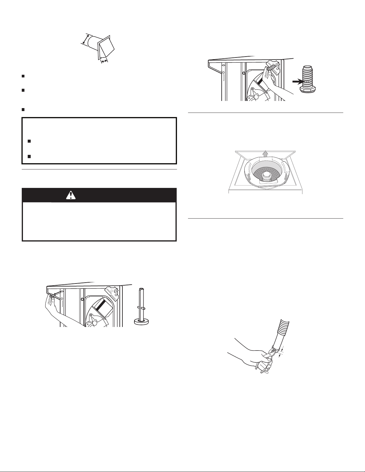
Install the front leveling legs
1. Examine the front leveling legs. Find the diamond marking.
2. Screw front legs by hand, into
braces in the front corners. Use wrench to finish turning the
legs until the diamond marking is no longer visible.
3. Slowly stand the washer/dryer upright.
the holes in the triangular
Improper venting can cause moisture and lint to collect
indoors, which may result in:
Moisture damage to woodwork, furniture, paint, wallpaper,
carpets, etc.
Housecleaning problems and health problems.
Install Leveling Legs
WARNING
Excessive Weight Hazard
Use two or more people to move and install
washer/dryer.
Failure to do so can result in back or other injury.
To protect the floor, use a large flat piece of cardboard from the
shipping carton. Gently place the washer/dryer on its side, on the
cardboard.
Install the rear leveling legs
1. Push legs into holes in rear corners until they snap into place.
Remove Foam Packing
1. Open the washer lid. The latch under the dryer will keep
the lid open.
2. Pull the foam packing ring out of the washer.
NOTE: Keep the foam ring and use it when transporting your
washer/dryer. This packing material is used to keep the washer
tub stable during transport.
Connect Drain Hose
Proper connection of the drain hose protects your floors from
damage due to water leakage. To keep the drain hose from
coming off or leaking, it must be installed according to the
following instructions:
IMPORTANT: To ensure proper installation, this procedure must
be followed exactly.
1. Check the drain hose to see whether it is the proper length.
2. Wet the inside of the straight end of the drain hose with tap
water.
IMPORTANT: Do not use any lubricant other
3. Squeeze ears of the silver double-wire clamp with pliers to
open. Place clamp over the straight end of the drain hose
¼" (6.4 mm) from the end.
than wate
r.
2. Check adjustability of rear legs by pushing in one leg. The
other leg should come out. Check both legs. If they do not
move freely, repeat Step 1.
6
¼"
(6.4 mm)
4. Open clamp. Twist hose back and forth while pushing onto
A
drain connector on the side of the washer/dryer. Continue until
hose contacts the ribbed stops on the cabinet.
5. Place clamp over the area marked “CLAMP.” Release clamp.
For laundry tub or standpipe drain systems
1. Make sure drain hose form is in correct position.
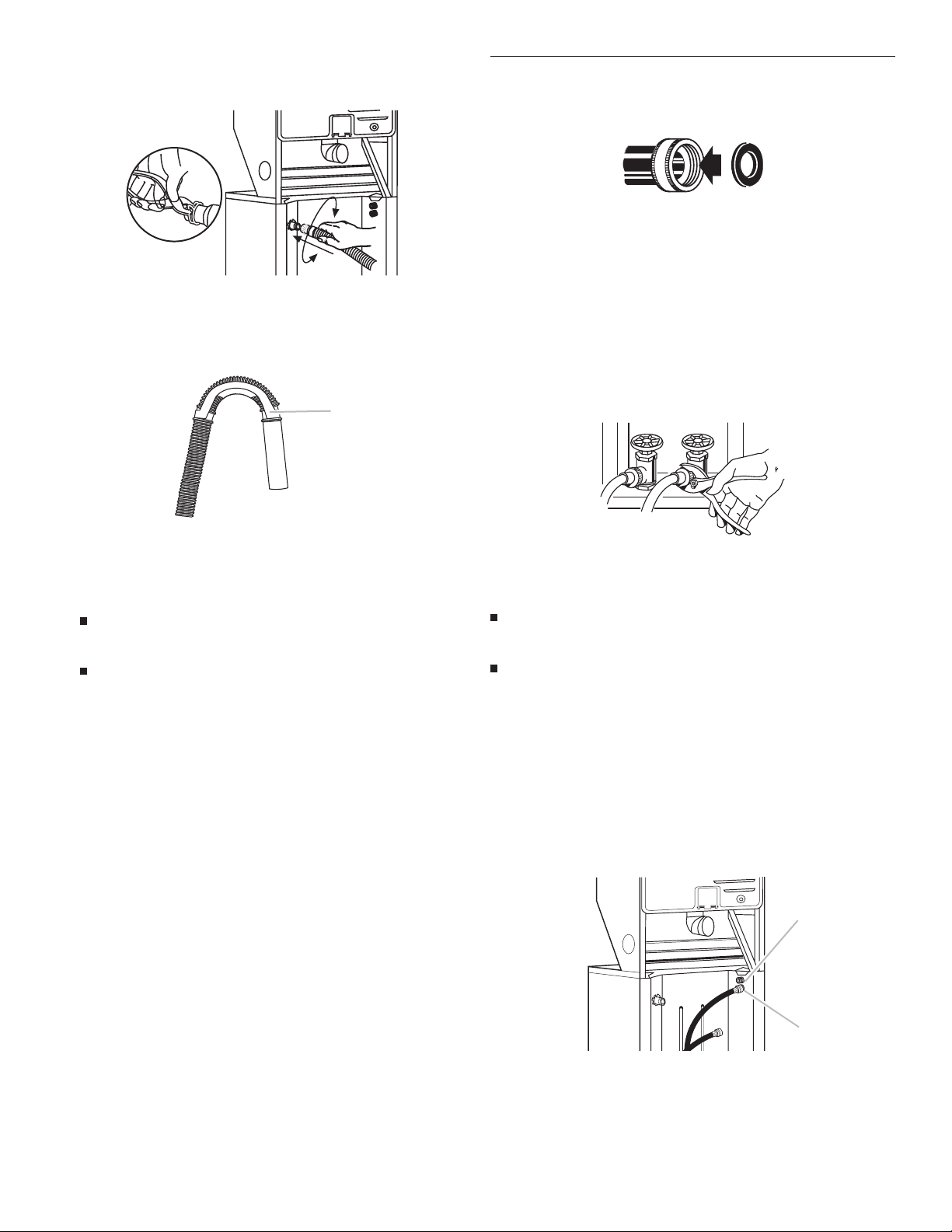
Connect Inlet Hoses
1. Insert a new flat washer into each end of the inlet hoses
(not provided). Firmly seat the washers in the couplings.
A B
A. Coupling
B. Washer
Connect the inlet hoses to the water faucets
Make sure the washer basket is empty.
1. Attach hose to the hot water faucet. Screw on coupling by
hand until it is seated on the washer.
2. Attach hose to the cold water faucet. Screw on coupling by
hand until it is seated on the washer.
3. Using pliers, tighten the couplings with an additional two-
thirds turn.
A. Drain hose form
2. Put the hooked end of drain hose into laundry tub or
standpipe. Rotate hook to eliminate kinks.
To keep drain water from going back into the washer:
Do not force excess drain hose into standpipe. Hose
should be secure but loose enough to provide a gap
for air.
Do not lay excess hose on the bottom of the laundry tub.
For use with floor drain
Do not install the drain hose form onto the corrugated drain hose.
You may need additional parts. See Floor drain under “Tools and
Parts.”
: Do not overtighten or use tape or sealants on the valve.
NOTE
Damage to the valves can result.
Clear the water lines
Run water through both faucets and inlet hoses, into a laundry
tub, drainpipe, or bucket to get rid of particles in the water
lines that might clog the inlet valve screens.
Check the temperature of the water to make sure that the hot
water hose is connected to the hot water faucet and that the
cold water hose is connected to the cold water faucet.
Connect the inlet hoses to the washer
1. Attach the hot water hose to the bottom inlet valve. Attaching
the hot water hose first makes it easier to tighten connection
with pliers.
2. Screw on coupling by hand until it is seated on the washer.
3. Using pliers, tighten the couplings with an additional two-
thirds turn.
NOTE: Do not overtighten
Damage to the valves can result.
or use tape or sealants on the valve.
A
B
A. Cold water inlet valve (top)
B. Hot water inlet valve (bottom)
7
4. Attach the cold water hose to the top inlet valve.
G
5. Screw on coupling by hand until it is seated on the washer.
6. Using pliers, tighten the couplings with an additional two-
thirds turn.
NOTE: Do not overtighten or use tape or sealants on the valve.
Damage to the valves can result.
If you are working in a closet or recessed area
Move the washer/dryer into its final location and remove
cardboard from under washer/dryer. Remove the access panel by
removing three Phillips-head screws and one bumper, located
the top of the access panel. Set panel, screws, and bumper aside.
Complete hookup of water hoses and (on gas models) the flexible
gas connector through the access area. Replace access panel
upon completion of washer/dryer installation.
at
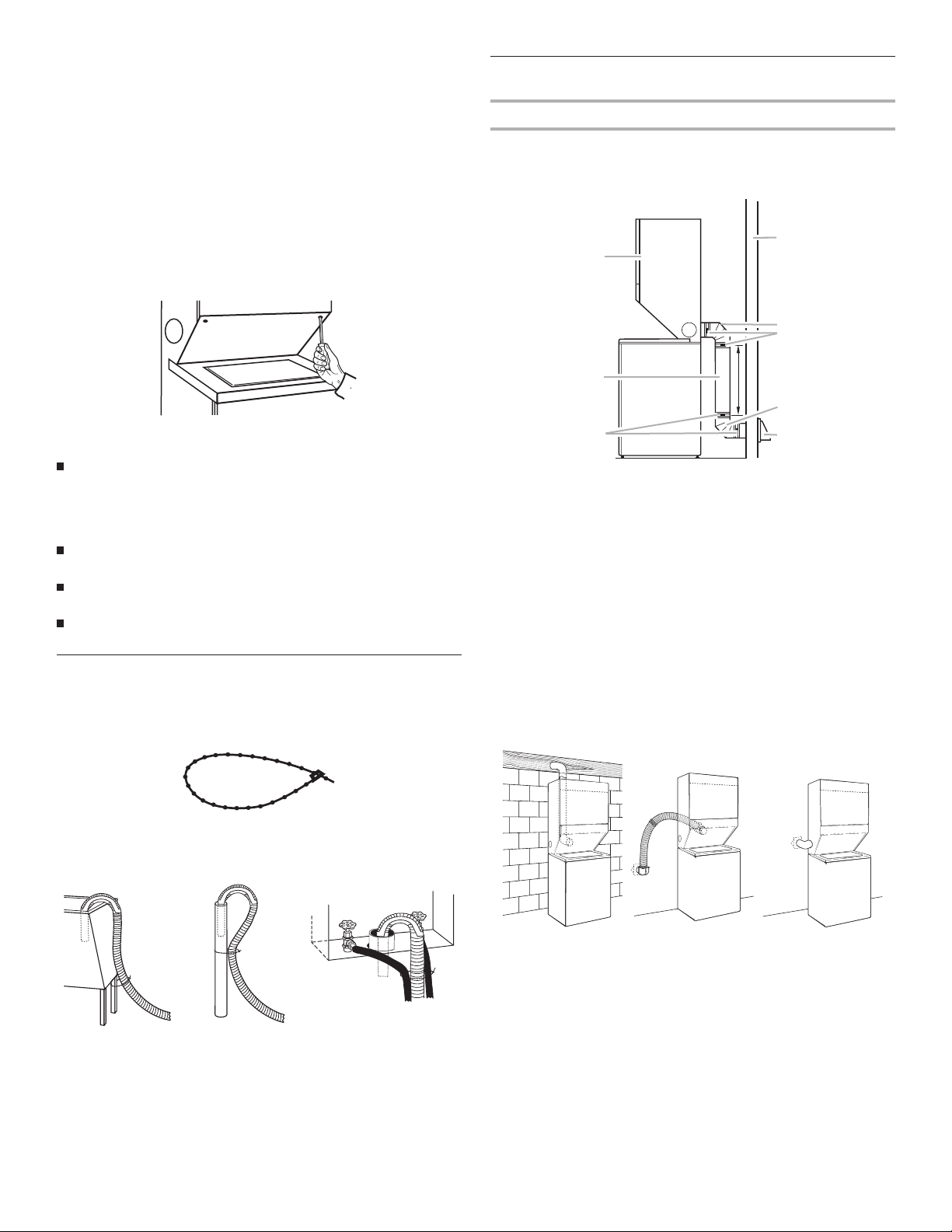
Plan Vent System
Choose your exhaust installation type
Recommended exhaust installations
Typical installations vent the dryer from the rear of the washer/
dryer. Other installations are possible.
D
A
E
F
B
Check for leaks
Turn on the water faucets and check for leaks. A small amount
of water might enter the washer. You will drain this water later.
NOTE: Replace inlet hoses after 5 years of use to reduce the risk
of hose failure. Record hose installation or replacement dates for
future reference.
If you connect only one water hose, you must cap off the
remaining water inlet port.
Periodically inspect and replace hoses if bulges, kinks, cuts,
wear, or leaks are found.
The apparatus must be connected to the water faucets using
the new hoses. Do not use old hoses.
Secure Drain Hose
1. Move the washer/dryer to its final location and remove any
cardboard used to move the washer/dryer.
2. Locate the plastic strap included in the parts package.
Plastic strap
3. Wrap the drain hose to the laundry tub leg or standpipe with
the plastic strap (A or B below) and secure.
C
A. Dryer
B. Rigid metal or flexible metal vent
C. Clamps
D. Wall
H
E. Elbow
F. Clamps
G. Elbow
H. Exhaust hood
Optional exhaust installations
This washer/dryer can be converted to exhaust out the right
or left side. To convert the washer/dryer, use Side Exhaust Kit
Part Number 279823. If your washer/dryer was previously
exhausted from the right or left side, it can be converted to rear
exhaust by using standard offset connections.
in the side, one of the following plugs can be added:
692790 (white)
3977784 (biscuit)
Follow the instructions in the kit to install. Kits are available from
the dealer from whom you purchased your washer/dryer.
To cover the hole
CBA
If the water faucets and the drain standpipe are recessed, put
the hooked end of the drain hose in the standpipe. Tightly
wrap the plastic strap around the water inlet hoses and the
drain hose (C above).
8
A B
A. Standard rear offset exhaust installation
B. Rear exhaust for offset close clearance connection
C. Left or right side exhaust installation
C
 Loading...