

Whirlpool KGCR055G, KGCT305G, KGCT365G, KGCS105G, YKGCT305G Owner's Manual
...
WHIRLPOOL & KITCHENAID
BUILT-IN GAS COOKTOPS
JOB AID
Part No. 4317256

FORWARD
This Job Aid, “Built-In Gas Cooktops,” (Part No. 4317256), provides the technician with information on the installation, operation, and service of KitchenAid & Whirlpool Built-In Gas Cooktops. It
is to be used as a training Job Aid and Service Manual. For specific information on the model
being serviced, refer to the “Use and Care Guide,” or “Tech Sheet” provided with the cooktop.
The Wiring Diagrams and Strip Circuits used in this Job Aid are typical and should be used for
training purposes only. Always use the Wiring Diagram supplied with the product when servicing
the unit.
GOALS AND OBJECTIVES
The goal of this Job Aid is to provide detailed information that will enable the service technician to
properly diagnose malfunctions and repair Built-In Gas Cooktops.
The objectives of this Job Aid are to:
• Understand and follow proper safety precautions.
• Successfully troubleshoot and diagnose malfunctions.
• Successfully perform necessary repairs.
• Successfully return the cooktop to proper operational status.
WHIRLPOOL CORPORATION assumes no responsibility for any repair
made on our products by anyone other than Authorized Factory Service
Technicians.
Copyright 1999, Whirlpool Corporation, Benton Harbor, MI 49022
- ii -

Table of Contents
PAGE
SPECIFICATIONS .................................................................................................................. 1-1
INSTALLATION HIGHLIGHTS................................................................................................ 2-1
Gas Supply Requirements ................................................................................................. 2-1
Electrical Requirements ..................................................................................................... 2-3
Installation.......................................................................................................................... 2-4
Converting The Cooktop For Use With L.P. Gas ............................................................... 2-6
PRODUCT OPERATION ........................................................................................................ 3-1
Electronic Ignition System ................................................................................................. 3-1
COMPONENT ACCESS ......................................................................................................... 4-1
Component Locations ........................................................................................................ 4-1
Removing The Maintop...................................................................................................... 4-2
Removing A Venturi & Spark Ignitor .................................................................................. 4-3
Removing A Spark Module & Power Cord......................................................................... 4-4
Removing An Ignitor Switch & A Gas Valve ...................................................................... 4-5
Removing The Gas Manifold ............................................................................................. 4-6
COMPONENT TESTING ........................................................................................................ 5-1
The Ignitor Switches .......................................................................................................... 5-1
DIAGNOSIS & TROUBLESHOOTING.................................................................................... 6-1
WIRING DIAGRAMS & STRIP CIRCUITS.............................................................................. 7-1
TECH TIPS ............................................................................................................................. 8-1
Surface Burners & Grates.................................................................................................. 8-1
Cleaning The Surface Burners .......................................................................................... 8-2
Requesting Assistance Or Service .................................................................................... 8-3
KitchenAid Gas Cooktop Warranty .................................................................................... 8-4
Whirlpool Gas Cooktop Warranty ...................................................................................... 8-5
- iii -

KITCHENAID MODEL & SERIAL NUMBER DESIGNATIONS
MODEL NUMBER
MODEL NUMBER
INTERNATIONAL SALES IND.
OR MARKETING CHANNEL
IF PRESENT
K=KITCHENAID BRAND
PRODUCT IDENTIFICATION:
EC=ELECTRIC COOKTOPS
GC=GAS COOKTOPS
MERCHANDISING SCHEME
C=CERAMIC GLASS
D=DOWNDRAFT VENT
G=GRILL/GRIDDLE
M=MODULAR DOWNDRAFT
N=INTERNATIONAL COLLECTION
P=PROFESSIONAL/COMMERCIAL
S=STANDARD/PORCELAIN METAL
T=TEMPERED GLASS
X=208 VOLT
E=ELECTRONICS
CAPACITY/SIZE /SERIES/CONFIG
1ST POSITION 2ND POSITION
1=STANDARD 0=30" WIDE
2=GRILL GRIDDLE 3=33" WIDE
3=TEMPERED GLASS 6=36" WIDE
4=COMMERCIAL 2=42" OR 12" WIDE
5=CERAMIC GLASS 5=15" WIDE
8=MODULAR/DOWNDRAFT
0=2 BURNER/ELEMENT SYSTEM
KGCS127 GBL 0
FEATURES
0=STANDARD ELEMENTS/BURNERS
1=RADIANT ELEMENTS
2=DUAL ELEMENTS
3=
4=
5=SEALED BURNERS/CAST ELEMENTS
6=5 BURNERS/ELEMENTS
7=HALOGEN ELEMENTS/6 BURNERS
8=TOUCH CONTROLS
9=INDUCTION
YEAR OF INTRODUCTION
G=1998 H=1999 J=2000
COLOR CODE
AL = Almond SS = Stainless
BL = Black WH = White
BT = Biscuit
ENGINEERING CHANGE (NUMERIC)
SERIAL NUMBER
SERIAL NUMBER X H 07 1 2 3 4 5
OXFORD
YEAR OF INTRODUCTION:
H = 1998, J = 1999, K = 2000
WEEK OF PRODUCTION
(7th WEEK)
PRODUCT SEQUENCE NUMBER
- iv -

WHIRLPOOL MODEL & SERIAL NUMBER DESIGNATIONS
MODEL NUMBER
S C S 30 0 4 G Q ----
MODEL NUMBER
INTERNATIONAL SALES IND.
OR MARKETING CHANNEL
IF PRESENT
PRODUCT GROUP:
R = ELECTRIC COOKING PRODUCTS
S = GAS COOKING PRODUCTS
G = WHIRLPOOL GOLD RANGE
PRODUCT IDENTIFICATION:
C = BUILT-IN COOKTOP
J = GOLD ELECTRIC COOKTOP
G = GOLD GAS COOKTOP
CONFIGURATION:
S = PORCELAIN / STEEL TOP
T = TEMPERED GLASS TOP
C = CERAMIC GLASS TOP
M = MODULAR DOWNDRAFT
MODEL SIZE:
20 = 20"
30 = 30"
36 = 36"
FEATURE VARIATIONS:
0 = LOW SPEED COIL ELECTRIC / OPEN-LOW END
BURNER GAS / OPEN BAYS
1 = HIGH SPEED COIL ELECTRIC / SEALED BURNERS
2 = CERAMIC RADIANT ELECTRIC
3 = CERAMIC RADIANT / DUAL
4 = MODULAR
- - - - - - - - - - - - - - - - - - - - - - - - - - - - - - - - - - - - - - - - - - - 0 = NO ELEMENTS / BURNERS
2 = TWO ELEMENT / BURNER
4 = FOUR ELEMENT / BURNER
5 = FIVE ELEMENT / BURNER
YEAR OF INTRODUCTION
G = 1998 H = 1999 J = 2000
COLOR CODE
B = Black S = Stainless Steel
N = Almond Z = Almond on Almond
Q = White on White W = White
ENGINEERING CHANGE (NUMERIC)
SERIAL NUMBER
SERIAL NUMBER X H 07 1 2 3 4 5
OXFORD
YEAR OF INTRODUCTION:
H = 1998, J = 1999, K = 2000
WEEK OF PRODUCTION
(7th WEEK)
PRODUCT SEQUENCE NUMBER
- v -
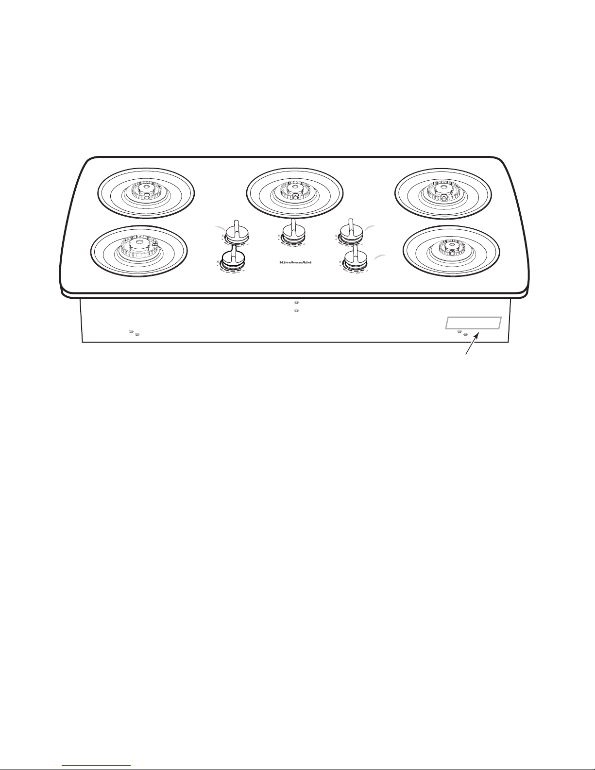
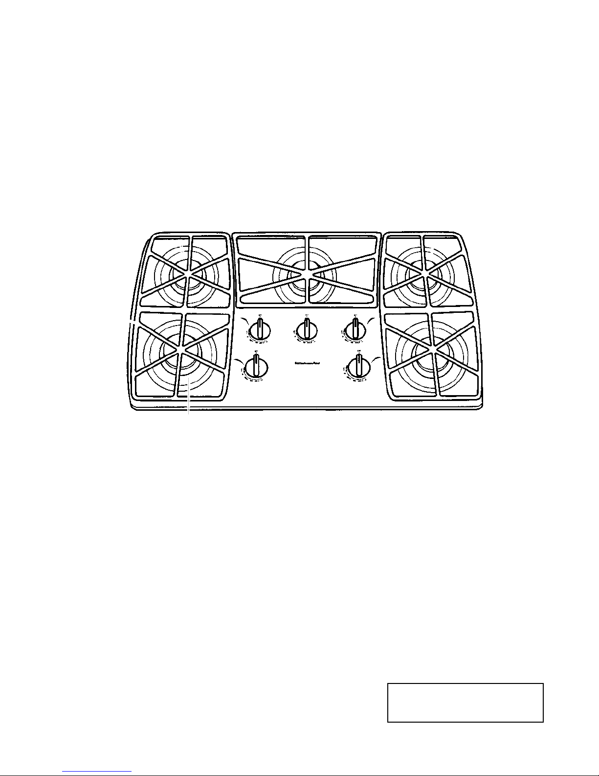
MODEL & SERIAL NUMBER LOCATION
The Model/Serial Number label is located on the underside of the cooktop burner box at the
location shown below.
Model & Serial Number
- vi -

IMPORTANT SAFETY INFORMATION
Your safety and the safety of others is very important.
Important safety messages have been provided in this Job Aid. Always read and obey all safety
messages.
This is the safety alert symbol.
This symbol alerts you to hazards that can kill or hurt you and others.
All safety messages will be preceded by the safety alert symbol and the word
“WARNING.”
All safety messages will identify the hazard, tell you how to reduce the chance of injury, and tell
you what can happen if the instructions are not followed.
WARNING: If the information in this Job Aid is not followed exactly, a fire or explosion may
result causing property damage, personal injury, or death.
Do not store or use gasoline or other flammable vapors and liquids in the vicinity of this or any
other appliance.
WHAT TO DO IF YOU SMELL GAS
• Do not try to light any appliance.
• Do not touch any electrical switch.
• Do not use any phone in your building.
• Immediately call your gas supplier from a neighbor’s phone. Follow the gas supplier’s
instructions.
• If you cannot reach your gas supplier, call the fire department.
Installation and service must be performed by a qualified installer, service agency or the gas
supplier.
- vii -

— NOTES —
- viii -
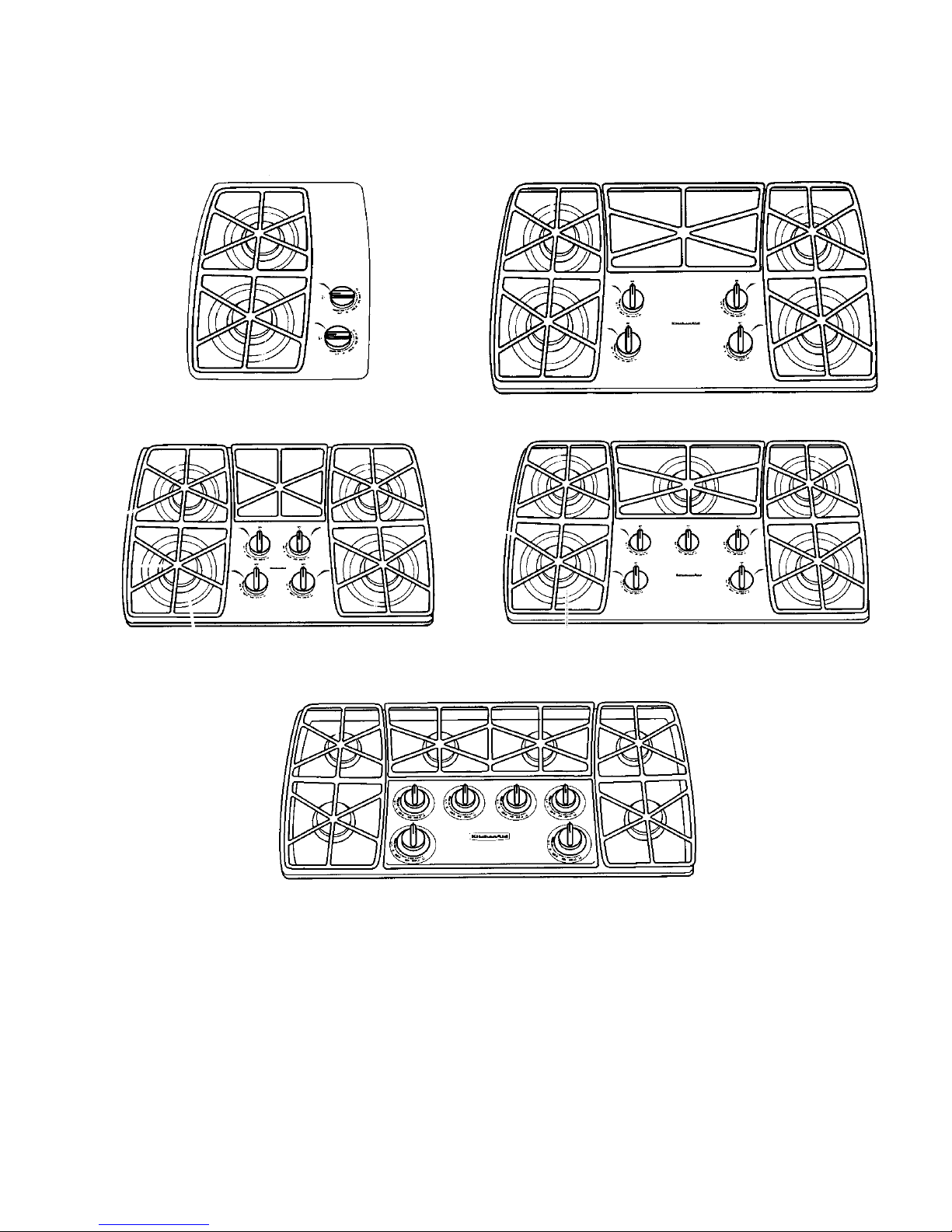
SPECIFICATIONS
KITCHENAID MODEL GAS COOKTOPS
KGCT055 & KGCR055G
KGCS105G, KGCT305G & YKGCT305G
KGCT365G
KGCS166G, KGCT366G & YKGCT366G
KGCS127G
1-1
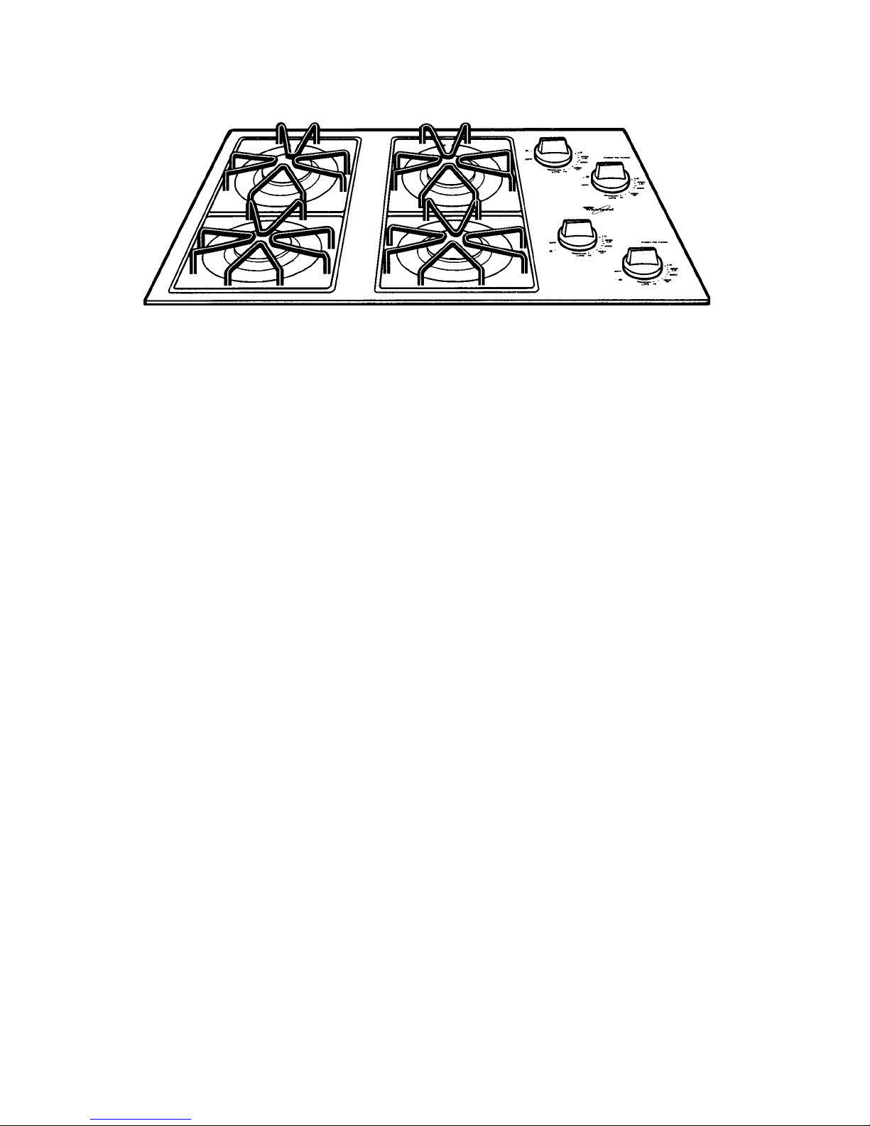
WHIRLPOOL MODEL GAS COOKTOPS
SCS3004G, SCS3014G, SCS3614G,
GLT3014G, & GLT3614G
1-2
30
a
",
36", & 42" GAS PORCELAIN & METAL COOKTOPS
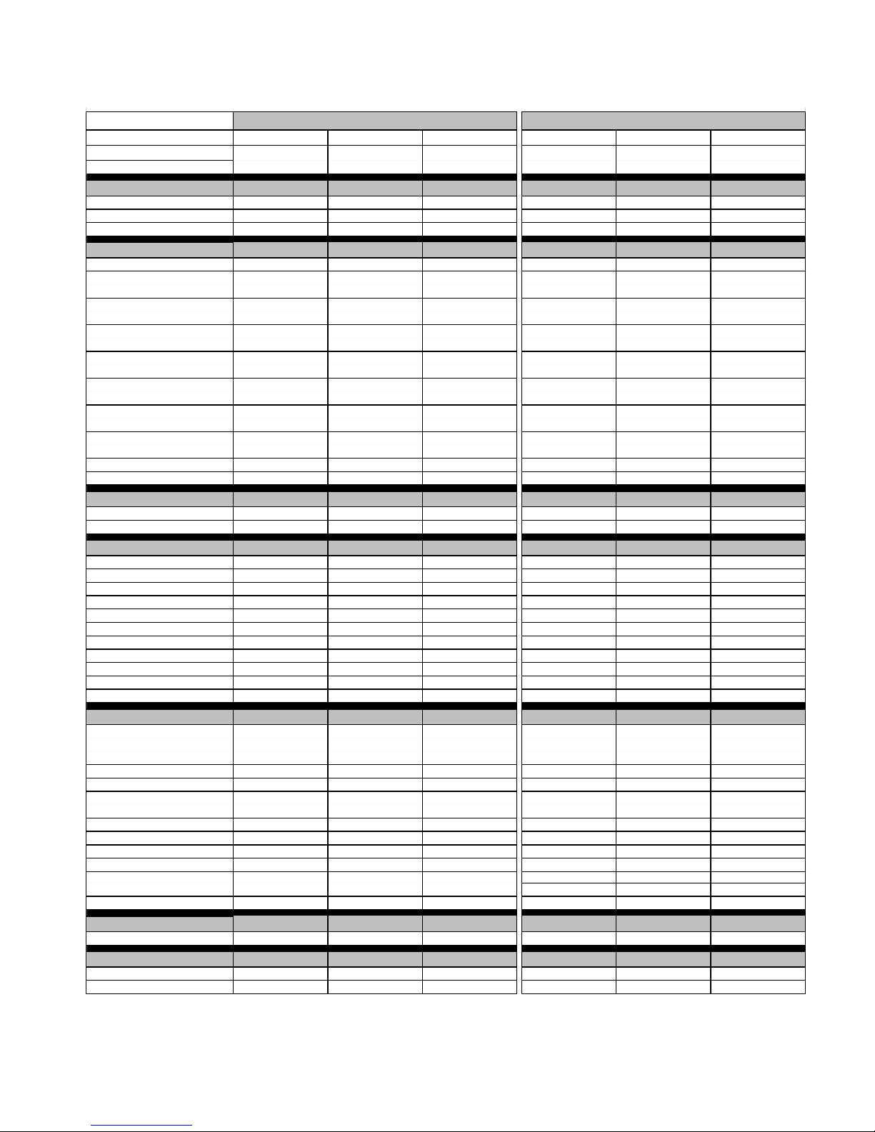
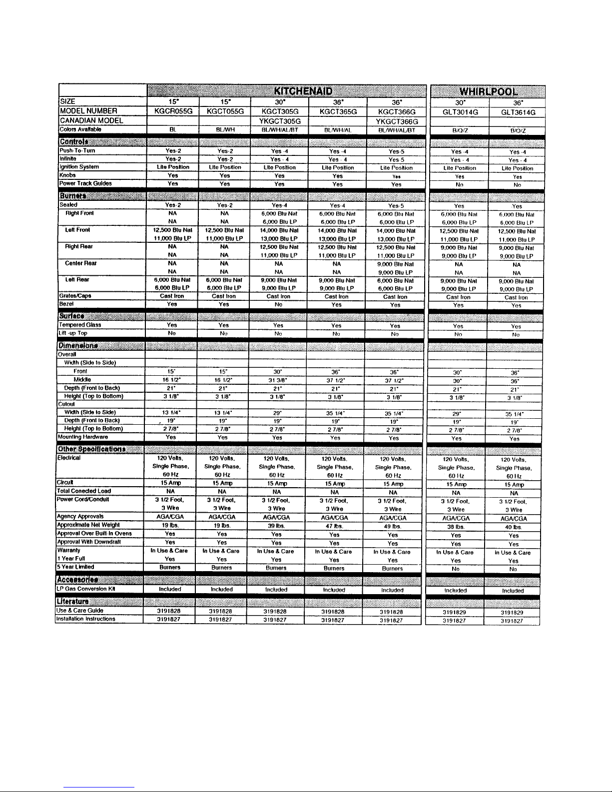
KITCHENAID WHIRLPOOL
SIZE 30" 36" 42" 30" 30" 36"
MODEL NUMBER KGCS105G KGCS166G KGCS127G SCS3004G SCS3014G SCS3614G
Colors Available BL/WH/AL/SS/BT BL/WH/AL/SS/BT BL/WH/AL/SS/BT W/N/S B/Q/Z/S B/Q/Z/S
Controls
Push-To-Turn Yes -4 Yes -5 Yes -6 Yes -4 Yes -4 Yes -4
Infinite Yes - 4 Yes - 5 Yes -6 Yes - 4 Yes - 4 Yes - 4
Ignition System Lite Position Lite Position Lite Position Lite Position Lite Position Lite Position
Burners
Sealed Yes-4 Yes-5 Yes-6 Yes - 4 Yes Yes
Right Front 6,000 Btu Nat 6,000 Btu Nat 6,000 Btu Nat 6,000 Btu Nat 6,000 Btu Nat 6,000 Btu Nat
Left Front 14,000 Btu Nat 14,000 Btu Nat 14,000 Btu Nat 9,000 Btu Nat 12,500 Btu Nat 12,500 Btu Nat
Right Rear 12,500 Btu Nat 12,500 Btu Nat 12,500 Btu Nat 9,000 Btu Nat 9,000 Btu Nat 9,000 Btu Nat
Center Right Rear NA NA 9,000 Btu Nat NA NA NA
Center Rear NA 9,000 Btu nat NA NA NA NA
Center Left Rear N A NA 6,000 Btu nat NA NA NA
Left Rear 9,000 Btu nat 6,000 Btu nat 9,000 Btu nat 9,000 Btu nat 9,000 Btu nat 9,000 Btu Nat
Grates Cast Iron Cast Iron Cast Iron Square-Stamped Square-Cast Iron Square-Cast Iron
Bezel No No No No Yes Yes
Surface
Porcelain/Metal Yes Yes Yes Yes Yes Yes
Lift -up Top No No No No No No
Dimensions
Overall
Width (Side to Side)
Front 30" 36" 42" 30 " 3 0" 3 6"
Middle 31 3/8" 37 1/2" 43 1/2" 31 3/8" 31 3/8" 37 1/2"
Depth (Front to Back) 21 " 21 " 21" 2 1" 2 1" 2 1"
Height (Top to Bottom) 3 3/8" 3 3/8" 3 3/8" 3 3/8" 3 3/8" 3 3/8"
Cutout
Width (Side to Side) 29 " 35 1/4" 40 1/2" 29" 2 9" 35 1/4"
Depth (Front to Back) 19 " 19 " 19" 1 9" 1 9" 1 9"
Height (Top to Bottom) 2 7/8" 2 7/8" 2 7/8" 2 7/8" 2 7/8" 2 7/8"
Mounting Hardware Yes Yes Yes Yes Yes Yes
Other Specifications
Electrical 120 Volts, 120 Volts, 120 Volts, 120 Volts, 120 Volts, 120 Volts,
Circuit 15 Amp 15 Amp 15 Amp 15 Amp 15 Amp 15 Amp
Total Conected Load NA NA NA NA NA NA
Power Cord/Conduit 3 1/2 Foot, 3 1/2 Foot, 3 1/2 Foot, 3 1/2 Foot, 3 1/2 Foot, 3 1/2 Foot,
Agency Approvals AGA/CGA AGA/CGA AGA/CGA AGA AGA/CGA AGA
Approximate Net Weight 38 lbs. 42 lbs. 45 lbs. 35 lbs. 35 lbs. 39 lbs.
Approval Over Built-in Ovens Yes Yes Yes Yes Yes Yes
Approval With Downdraft Yes Yes Yes Yes Yes Yes
Warranty In Use & Care In Use & Care In Use & Care In Use & Care In Use & Care In Use & Care
1 Year Full Yes Yes Yes Yes Yes Yes
5 Year Limited Burners Burners Burners No No No
Accessories
LP Gas Conversion Kit Included Included Included Included Included Included
Literature
Use & Care Guide 3191828 3191828 3191828 3191829 3191829 3191829
Installation Instructions 3191827 3191827 3191827 3191827 3191827 3191827
6,000 Btu LP 6,000 Btu LP 6,000 Btu LP 6,000 Btu LP 6,000 Btu LP 6,000 Btu LP
13,000 Btu LP 13,000 Btu LP 13,000 Btu LP 9,000btu LP 11,000 Btu LP 11,000 Btu LP
11, 000 Btu LP 11, 000 Btu LP 11, 000 Btu LP 9,000btu LP 9,000btu LP 9,000btu LP
NA NA 9,000 Btu LP NA NA NA
NA 9,000 Btu LP NA NA NA NA
NA NA 6,000 Btu LP NA NA NA
9,000 Btu LP 6,000 Btu LP 9,000 Btu LP 9,000btu LP 9,000btu LP 9,000btu LP
Single Phase, Single Phase, Single Phase, Single Phase, Single Phase, Single Phase,
60 Hz 60 Hz 60 Hz 60 Hz 60 Hz 60 Hz
3 Wire 3 Wire 3 Wire 3 Wire 3 Wire 3 Wire
1-3
15
",
30", & 36" GAS GLASS COOKTOPS
1-4
INSTALLATION HIGHLIGHTS
GAS SUPPLY REQUIREMENTS
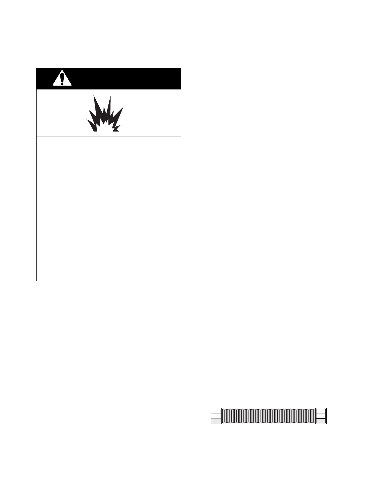
2. Input ratings shown on the model/serial
WARNING
Explosion Hazard
Use a new AGA approved gas supply
line.
Install a shutoff valve.
Securely tighten all gas connections.
If connected to LP gas, have a qualified
person make sure gas pressure does
not exceed 14" water column.
Examples of a qualified person includes licensed heating personnel, authorized gas company personnel, and
authorized service personnel.
Failure to do so can result in death, explosion, or fire.
Observe all governing codes and ordinances.
Important: The cooktop must be connected
to a regulated gas supply.
1. This installation must conform with local
codes and ordinances. In the absence of
local codes, installations must conform
with American National Standard, National
Fuel Gas Code ANSI Z223.1— latest edition*** or CANI — B149.1 or 2**.
**Canadian Standard Association
178 Rexdale Boulevard
Etobicoke, Ontario M9W 1R3
rating plate are for elevations up to 2,000
feet (610 m). For elevations above 2,000
feet (610 m), ratings are reduced at a rate
of 4% for each 1,000 feet (305 m) above
sea level.
3. The cooktop is equipped for use with
NATURAL gas. It is design-certified by the
American Gas Association for NATURAL
and L.P. gases with the appropriate conversion. The model/serial rating plate, located on the underside of the burner box,
has information on the type of gas that can
be used. If this information does not agree
with the type of gas available, check with
the local gas supplier. See Page 2-6 for
L.P. gas conversion instructions.
4. Provide a gas supply line of 3/4" rigid pipe
to the cooktop location. A smaller size pipe
on long runs may result in insufficient gas
supply. Pipe-joint compounds, suitable for
use with L.P. gas, must be used. With L.P
gas, piping or tubing size can be a minimum of 1/2". L.P. gas suppliers usually
determine the size and materials used on
the system.
5. If local codes permit, a new A.G.A. designcertified, 4-5 foot (1.2-1.5 m) long, 1/2" or
3/4" I.D., flexible metal appliance connector is recommended for connecting this
cooktop to the gas supply line. Do not kink
or damage the flexible connector when
moving the cooktop. The pressure regulator has 3/8" female pipe threads. You will
need to determine the fittings required,
depending on the size of your gas supply
line, flexible metal connector and shutoff
valve.
Flexible Gas Supply Line
***American Gas Association
1515 Wilson Boulevard
Arlington, Virginia 22209
2-1
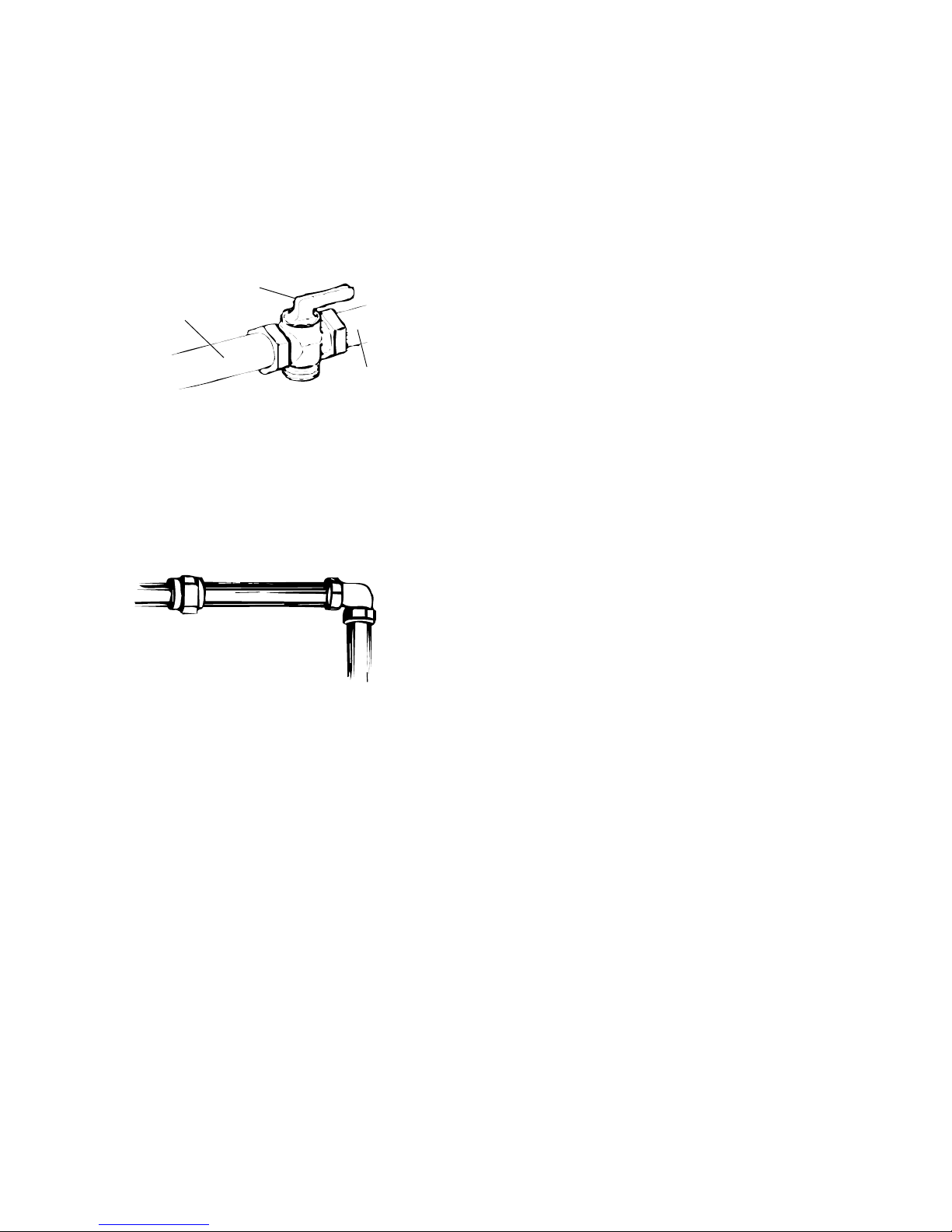
6. The supply line shall be equipped with an
approved shutoff valve. This valve should
be located in the same room as the cooktop
and should be in a location that allows
ease of opening and closing. Do not block
access to the shutoff valve. The valve is
for turning on or shutting off gas to the
appliance.
Shutoff Valve
(open)
To Cooktop
Gas Supply
Line
8. The regulator must be checked at a minimum 1-inch (2.5 cm) water column above
the set pressure. The inlet pressure to the
regulator should be as follows for operation and checking the regulator setting:
NATURAL GAS
Set pressure: 4 inches (10.2 cm).
Supply pressure: 7-14 inches (17.8 cm to 35.5
cm) maximum.
L.P. GAS
Minimum pressure: 10 inches (25.4 cm).
Supply pressure: 14 inches (35.5 cm).
7. If rigid pipe is used as a gas supply line, a
combination of pipe fittings must be used
to obtain an in-line connection to the
cooktop. All strains must be removed from
the supply and fuel lines so cooktop will be
level and in line.
Rigid Pipe
9. Line Pressure Testing:
Testing Above 1/2 psi (3.5 kPa)
(14 inches (35.6 cm)) W.C. (gauge)
The cooktop and its individual shutoff valve
must be disconnected from the gas supply
piping system during any pressure testing
of that system at test pressures greater
than 1/2 psig (3.5kPa).
Testing Below 1/2 psi (3.5 kPa) (14
inches (35.6 cm)) W.C. (gauge), Or
Lower
The cooktop must be isolated from the gas
supply piping system by closing its individual manual shutoff valve during any
pressure testing of the gas supply piping
system at test pressures equal to or less
than 1/2 psig (3 5 kPa).
2-2
 Loading...