

Whirlpool KECS161G, RCS3004G, RCS2002G, RCS2012G, RCS3014G Owner's Manual
...
WHIRLPOOL & KITCHENAID
BUILT-IN ELECTRIC
COOKTOPS
JOB AID
Part No. 4317269

FORWARD
This Job Aid, “Whirlpool & KitchenAid Built-In Electric Cooktops,” (Part No. 4317269), provides
the technician with information on the installation and service of Whirlpool & KitchenAid Built-In
Electric Cooktops. It is to be used as a training Job Aid and Service Manual. For specific information on the model being serviced, refer to the “Use and Care Guide,” or “Tech Sheet” provided
with the cooktop.
The Wiring Diagrams used in this Job Aid are typical and should be used for training purposes
only. Always use the Wiring Diagram supplied with the product when servicing the unit.
GOALS AND OBJECTIVES
The goal of this Job Aid is to provide detailed information that will enable the service technician to
properly diagnose malfunctions and repair Built-In Electric Cooktops.
The objectives of this Job Aid are to:
• Understand and follow proper safety precautions.
• Successfully troubleshoot and diagnose malfunctions.
• Successfully perform necessary repairs.
• Successfully return the cooktop to proper operational status.
WHIRLPOOL CORPORATION assumes no responsibility for any repair
made on our products by anyone other than Authorized Factory Service
Technicians.
Copyright 1999, Whirlpool Corporation, Benton Harbor, MI 49022
- ii -

Table of Contents
PAGE
SPECIFICATIONS .................................................................................................................. 1-1
INSTALLATION HIGHLIGHTS................................................................................................ 2-1
Electrical Requirements ..................................................................................................... 2-1
Electrical Connections ....................................................................................................... 2-2
Installation.......................................................................................................................... 2-4
COMPONENT ACCESS ......................................................................................................... 3-1
Component Locations ........................................................................................................ 3-1
Removing The Maintop...................................................................................................... 3-2
Removing The Indicator Light, An Element Control,
A Coil Receptacle, & The T.O.D. .................................................................................... 3-4
Removing The Ceramic Glass Maintop ............................................................................. 3-6
COMPONENT TESTING ........................................................................................................ 4-1
WIRING DIAGRAMS............................................................................................................... 5-1
TECH TIPS ............................................................................................................................. 6-1
- iii -

KITCHENAID MODEL & SERIAL NUMBER DESIGNATIONS
MODEL NUMBER
MODEL NUMBER
INTERNATIONAL SALES IND.
OR MARKETING CHANNEL
IF PRESENT
K=KITCHENAID BRAND
PRODUCT IDENTIFICATION:
EC=ELECTRIC COOKTOPS
GC=GAS COOKTOPS
MERCHANDISING SCHEME
C=CERAMIC GLASS
D=DOWNDRAFT VENT
G=GRILL/GRIDDLE
M=MODULAR DOWNDRAFT
N=INTERNATIONAL COLLECTION
P=PROFESSIONAL/COMMERCIAL
S=STANDARD/PORCELAIN METAL
T=TEMPERED GLASS
X=208 VOLT
E=ELECTRONICS
CAPACITY/SIZE /SERIES/CONFIG
1ST POSITION 2ND POSITION
1=STANDARD 0=30" WIDE
2=GRILL GRIDDLE 3=33" WIDE
3=TEMPERED GLASS 6=36" WIDE
4=COMMERCIAL 2=42" OR 12" WIDE
5=CERAMIC GLASS 5=15" WIDE
8=MODULAR/DOWNDRAFT
0=2 BURNER/ELEMENT SYSTEM
KECS161 GBL 0
FEATURES
0=STANDARD ELEMENTS/BURNERS
1=RADIANT ELEMENTS
2=DUAL ELEMENTS
3=
4=
5=SEALED BURNERS/CAST ELEMENTS
6=5 BURNERS/ELEMENTS
7=HALOGEN ELEMENTS/6 BURNERS
8=TOUCH CONTROLS
9=INDUCTION
YEAR OF INTRODUCTION
G=1998 H=1999 J=2000
COLOR CODE
AL = Almond SS = Stainless
BL = Black WH = White
BT = Biscuit
ENGINEERING CHANGE (NUMERIC)
SERIAL NUMBER
SERIAL NUMBER X H 07 1 2 3 4 5
OXFORD
YEAR OF INTRODUCTION:
H = 1998, J = 1999, K = 2000
WEEK OF PRODUCTION
(7th WEEK)
PRODUCT SEQUENCE NUMBER
- iv -

WHIRLPOOL MODEL & SERIAL NUMBER DESIGNATIONS
MODEL NUMBER
R C S 30 0 4 G N ----
MODEL NUMBER
INTERNATIONAL SALES IND.
OR MARKETING CHANNEL
IF PRESENT
PRODUCT GROUP:
R = ELECTRIC COOKING PRODUCTS
S = GAS COOKING PRODUCTS
G = WHIRLPOOL GOLD RANGE
PRODUCT IDENTIFICATION:
C = BUILT-IN COOKTOP
J = GOLD ELECTRIC COOKTOP
G = GOLD GAS COOKTOP
CONFIGURATION:
S = PORCELAIN / STEEL TOP
T = TEMPERED GLASS TOP
C = CERAMIC GLASS TOP
M = MODULAR DOWNDRAFT
MODEL SIZE:
20 = 20"
30 = 30"
36 = 36"
FEATURE VARIATIONS:
0 = LOW SPEED COIL ELECTRIC / OPEN-LOW END
BURNER GAS / OPEN BAYS
1 = HIGH SPEED COIL ELECTRIC / SEALED BURNERS
2 = CERAMIC RADIANT ELECTRIC
3 = CERAMIC RADIANT / DUAL
4 = MODULAR
- - - - - - - - - - - - - - - - - - - - - - - - - - - - - - - - - - - - - - - - - - - 0 = NO ELEMENTS / BURNERS
2 = TWO ELEMENT / BURNER
4 = FOUR ELEMENT / BURNER
5 = FIVE ELEMENT / BURNER
YEAR OF INTRODUCTION
G = 1998 H = 1999 J = 2000
COLOR CODE
B = Black S = Stainless Steel
N = Almond Z = Almond on Almond
Q = White on White W = White
ENGINEERING CHANGE (NUMERIC)
SERIAL NUMBER
SERIAL NUMBER X H 07 1 2 3 4 5
OXFORD
YEAR OF INTRODUCTION:
H = 1998, J = 1999, K = 2000
WEEK OF PRODUCTION
(7th WEEK)
PRODUCT SEQUENCE NUMBER
- v -
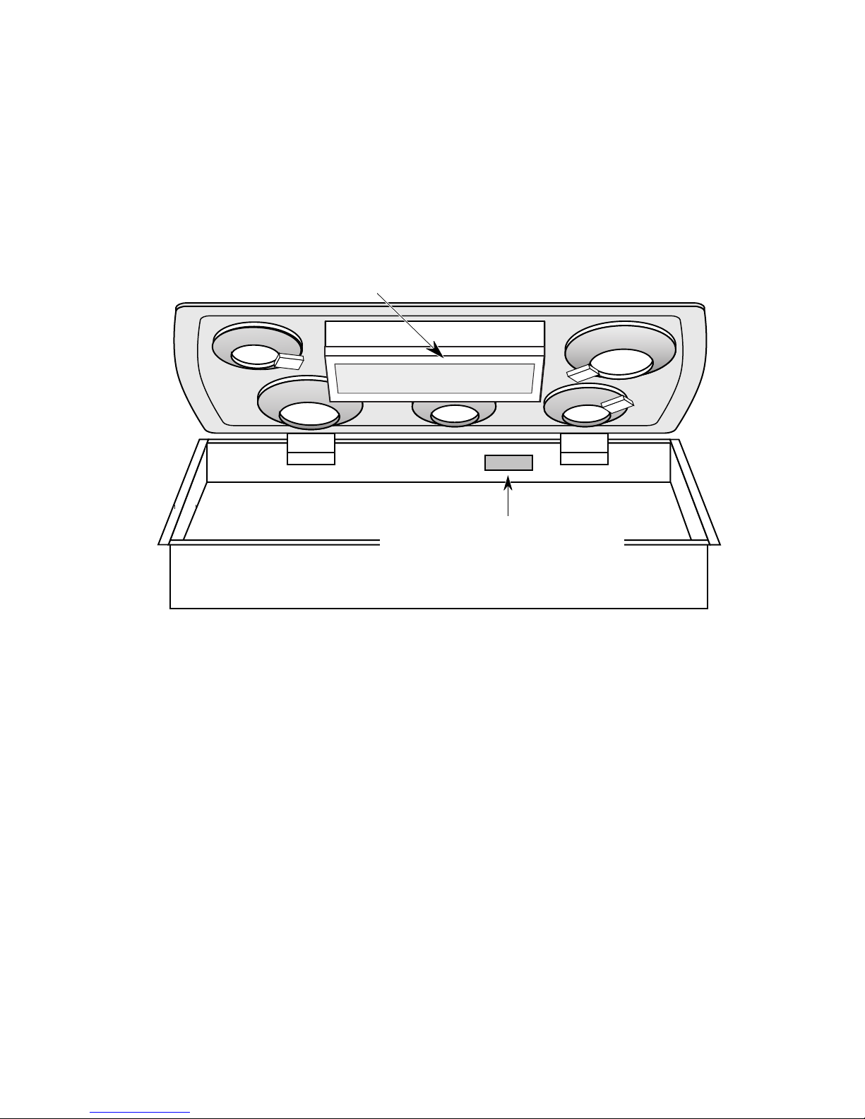
MODEL & SERIAL NUMBER LABEL
AND WIRING DIAGRAM LOCATIONS
The Model/Serial Number label and Wiring Diagram locations are shown below.
Wiring Diagram Location
(on inside of switch box cover)
Model & Serial Number
Location* (on inside rear of
burner box)
* Whirlpool models & KitchenAid Ceramic glass models located on bottom of burner box.
- vi -

IMPORTANT SAFETY INFORMATION
Your safety and the safety of others is very important.
Important safety messages have been provided in this Job Aid. Always read and obey all
safety messages.
This is the safety alert symbol.
This symbol alerts you to hazards that can kill or hurt you and others.
All safety messages will be preceded by the safety alert symbol and the word
“WARNING.”
All safety messages will identify the hazard, tell you how to reduce the chance of injury, and tell
you what can happen if the instructions are not followed.
- vii -

— NOTES —
- viii -
SPECIFICATIONS
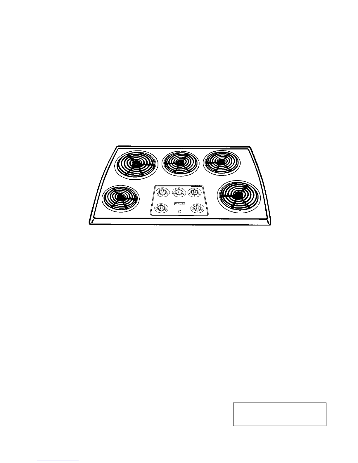
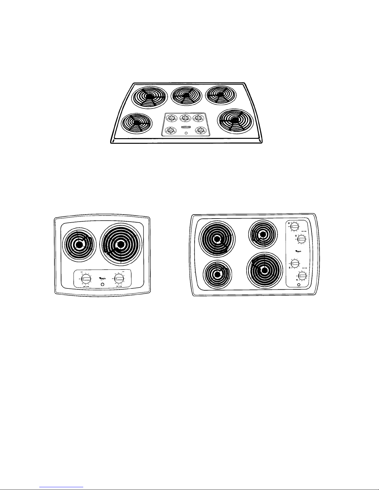
KITCHENAID MODEL ELECTRIC
PORCELAIN/METAL COIL COOKTOPS
KECS100G & KECS161G
WHIRLPOOL MODEL ELECTRIC
PORCELAIN/METAL COIL COOKTOPS
RCS2002G & RCS2012G
RCS3004G, RCS3014G, &
RCS3614G
1-1
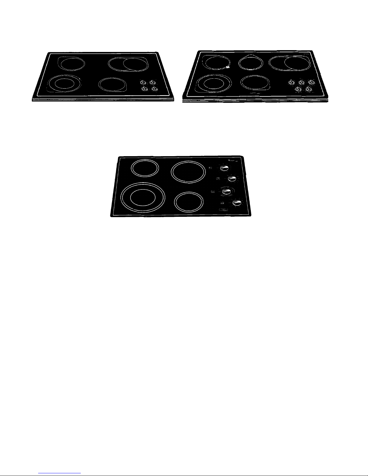
KITCHENAID MODEL ELECTRIC CERAMIC COOKTOPS
KECC501G, KECC502G,
YKECC502G, KECC507G, &
YKECC507G
KECC562G, KECC567G &
YKECC567G
WHIRLPOOL MODEL ELECTRIC CERAMIC COOKTOPS
RCC3024G, GJC3034G, &
GJC3634G
1-2
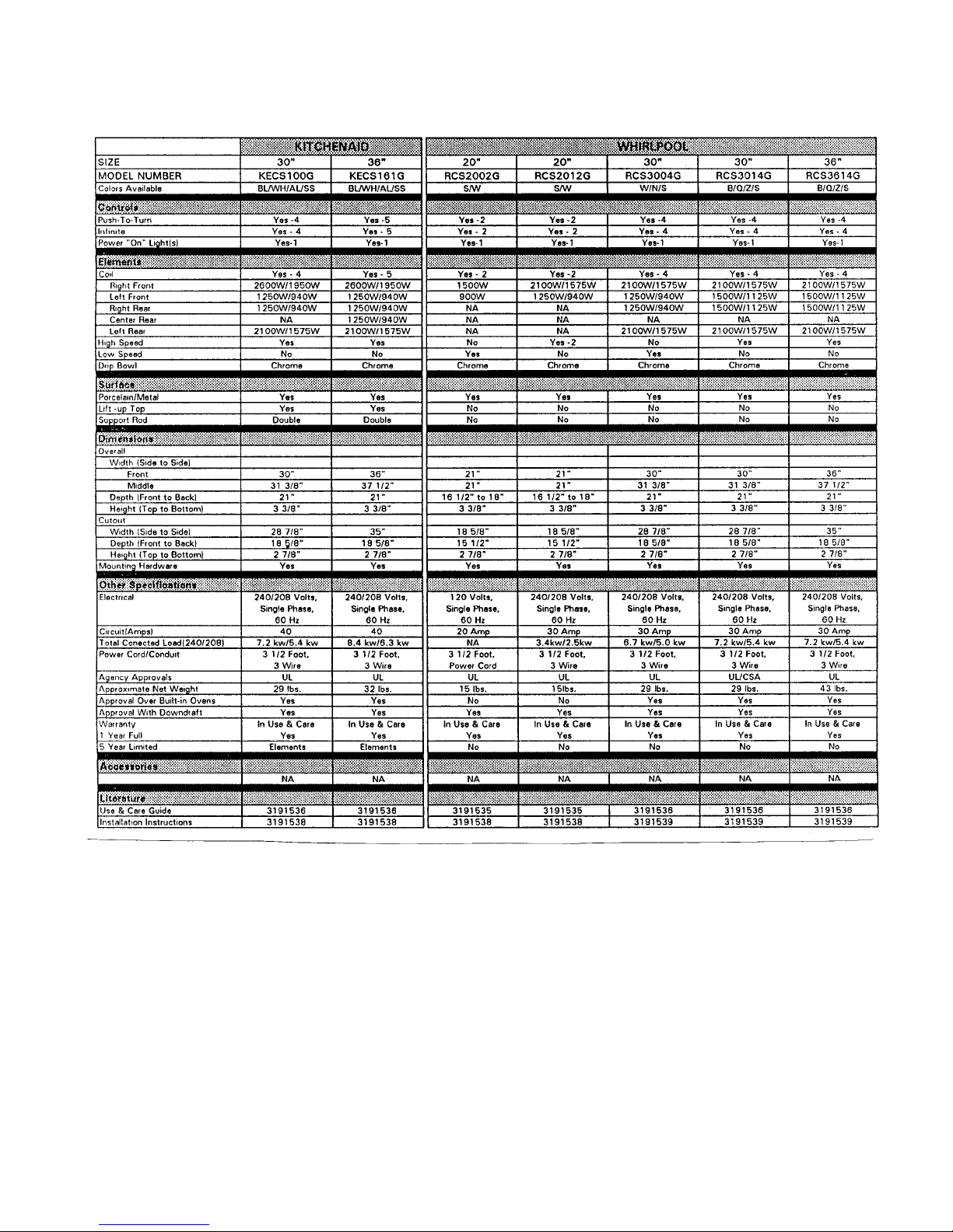
20", 30", & 36" ELECTRIC PORCELAIN / METAL COIL COOKTOPS
1-3
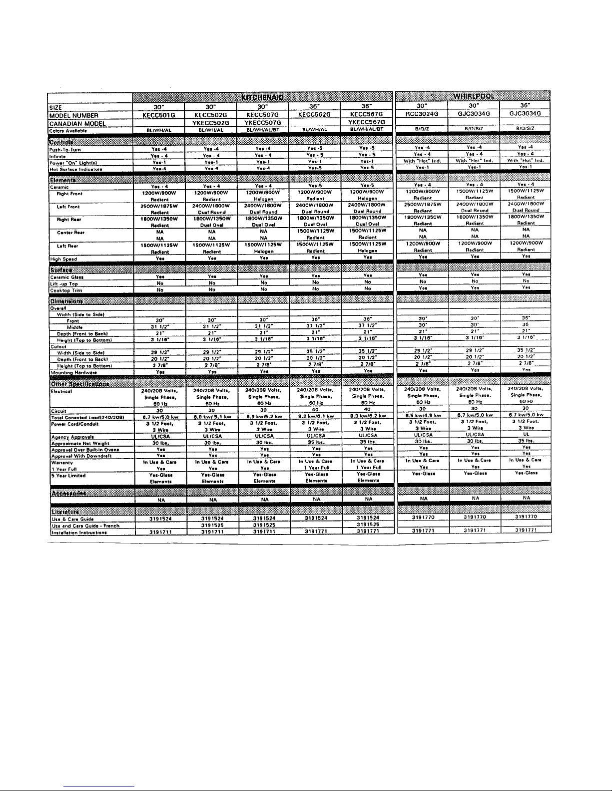
30" & 36" ELECTRIC CERAMIC COOKTOPS
1-4

INSTALLATION HIGHLIGHTS
ELECTRICAL REQUIREMENTS
If codes permit and a separate ground wire
is used, it is recommended that a qualified
electrician determine that the ground path
is adequate.
Do not ground to a gas pipe.
Check with a qualified electrician if you are
not sure whether the cooktop is properly
grounded.
Do not have a fuse in the neutral or ground
circuit.
240 VOLT COOKTOP
1. A three-wire or four-wire, single phase,
240-volt, 60-Hz, AC-only electrical supply
is required on a separate, 40-ampere circuit, fused on both sides of the line. A timedelay fuse or circuit breaker is recommended. The fuse size must not exceed
the circuit rating of the appliance specified
on the model/serial rating plate located on
the bottom of the cooktop.
THE COOKTOP MUST BE CONNECTED
WITH COPPER WIRE ONLY.
2. Wire sizes and connections must conform
to the requirements of the National Electrical Code ANSI/NFPA 70 — latest edition**, or CSA Standards C22.1-94, Canadian Electrical Code, Part 1 and C22.2 No.
0-M91 — latest edition*** and all local
codes and ordinances.
3. The cooktop should be connected directly
to the fused disconnect or circuit breaker
box through flexible, armored or non-metallic sheathed, copper cable. The flexible,
armored cable extending from the fuse
box or circuit breaker box should be connected directly to the junction box.
4. Locate the junction box to allow as much
slack as possible between the junction
box and the cooktop so that the cooktop
can be moved if servicing is ever necessary. Do Not cut the conduit.
5. A U.L. - or C.S.A.-listed conduit connector
must be provided at each end of the power
supply cable (at the cooktop and at the
junction box).
Copies of the standards listed above may be
obtained from:
**National Fire Protection Association
Batterymarch Park
Quincy, Massachusetts 02269
***Canadian Standard Association
178 Rexdale Boulevard
Etobicoke, Ontario M9W 1R3
2-1
 Loading...