

Page 1
Twin Tub Washing Machine
PARTS &
SERVICE Manual
NARSO MODELS
Doc No. WOI/washer/2001/009 Page No 1
Modified on date 03/08/2001 Subject to modification
Page 2
MODEL NUMBERS
SAP_MODEL_NO DESCRIPTION OLD_MODEL_NUMBER
1099 WASHING MACHINE -ROPER - APWH WWBDQ59E0
1100 WASHING MACHINE -SUPER PLUS - APWH WWBDS50E8
1104 WASHING MACHINE -SUPER PLUS -APWH WWBCP59E6
1108 WASHING MACHINE-SUPER+APWH-S.MARTIN-220V WWBDI58E3
1109 WASHING MACHINE -SUPER+ APWH -SURINAME WWBDJ58E4
1113 WASHING MACHINE -WWBCM58-E0A-APP.WHITE WWBCM58E0
1294 WASHING MACHINE-SUPER+APWH-S.MARTIN-110V WWBDH58E0
2254 WASHING M/C - 110 V AC, 60Hz APWH-PANAMA WWBDR58-E0A
2255 WASHING M/C-115 V AC,60Hz APWH-TRINIDAD WWBDT58-E6A
MODEL DETAILS
WWBCM58E0A WWBDM58E5A WWBDN58E0A
With pump With pump With pump
110v 110v 110v
WWBDH58E0A WWBDL58E0A WWBDI58E3A
No pump No pump No pump
110v 110v 220v
Doc No. WOI/washer/2001/009 Page No 2
Modified on date 03/08/2001 Subject to modification
Page 3

TWIN TUB WASHING MACHINE
CONTENTS
NARSO MODELS
S.NO DESCRIPTION PAGE NO
1. SPECIFICATIONS 6
2. SPECIAL FEATURES OF SUPER PLUS NEW & SUPER NEW 7
3. CONTROL & FUNCTIONS 8
4. EXPLODED VIEW AND PARTS LIST 10
5. WIRING DIAGRAM 16
6. FAULT FINDING GUIDE 17
7. COMPONENT CHECK GUIDE 18
Doc No. WOI/washer/2001/009 Page No 3
Modified on date 03/08/2001 Subject to modification
Page 4
Doc No. WOI/washer/2001/009 Page No 4
Modified on date 03/08/2001 Subject to modification
Page 5
SPECIFICATIONS
Doc No. WOI/washer/2001/009 Page No 5
Modified on date 03/08/2001 Subject to modification
Page 6

MODEL: SUPER PLUS NEW & SUPER NEW
NARSO MODELS
1. POWER SOURCE : 110V /60 Hz (Except model BDI58E3A)
2. CAPACITY WASH : 5 KG DRY WEIGHT
SPIN : 5 KG WET WEIGHT
3. OVERALL DIMENSIONS : W 750MM/D 490 MM/H-812MM
4. MACHINE WEIGHT PACKED : 37 KGS
UNPACKED : 30 KGS
5. MOTOR SPEED WASH : 1400 RPM+ 25 RPM
SPIN : 1400 RPM+ 25 RPM
6. MOTOR POWER WASH : 330 W
(INPUT) SPIN : 150 W
7. WASH SYSTEM : AGITATOR TYPE
8. SPIN SYSTEM : CENTRIFUGAL
9. WATER LEVEL SELECTION : 3
10. WATER CAPACITY HIGH : 50 L
MEDIUM : 43 L
LOW : 36 L
11. AGITATOR SPEED : 13 STROKES PER MINUTE
12. INDICATOR : BUZZER AT THE END OF
SUPER PLUS NEW – WASH/RINSE
SUPER NEW – WASH/RINSE & SPIN
13. DRIVE SYSTEM WASH : BELT & PLANETARY GEAR
SPN : DIRECT
14. WASH TIMER SETTINGS : 1 TO 15 MINUTES
15. SPIN TIMER SETTINGS : 1 TO 5 MINUTES (Super Plus New only)
16. TIMER WASH : ELCTRO MECHANICAL
SPIN : MECHANICAL (Super Plus New only)
Doc No. WOI/washer/2001/009 Page No 6
Modified on date 03/08/2001 Subject to modification
Page 7

FEATURES OF – SUPER PLUS NEW & SUPER NEW TWIN TUB
MACHINES
The following are of the main features available in – Super plus New and Super New semi
automatic washing machine:
⇒ Stainless steel spin basket with liquid balancing ring.
(Only for SUPER PLUS NEW MODEL)
⇒ Prepainted galvanized sheet for cabinet.
⇒ Unique agitator washing system
⇒ Towel hanger ( Only for SUPER PLUS NEW model)
⇒ True 5-kg wash & matched spin capacity.
⇒ Rat mesh
⇒ Transparent wash lid
⇒ Improved Spin shower option
⇒ Wheels for mobility
⇒ Buzzer indication
⇒ Electro mechanical wash timer
⇒ Drain hose routing on all four sides
⇒ Power card winding facility
⇒ Drain Pump in models BCM58 E0A, BDM58 E5A AND BDN58 E0A
⇒ Hinged wash lid and also easily accessible & can be hinged on the side
⇒ Fuse 3A – Enclosed in Polyphone cover
Doc No. WOI/washer/2001/009 Page No 7
Modified on date 03/08/2001 Subject to modification
Page 8

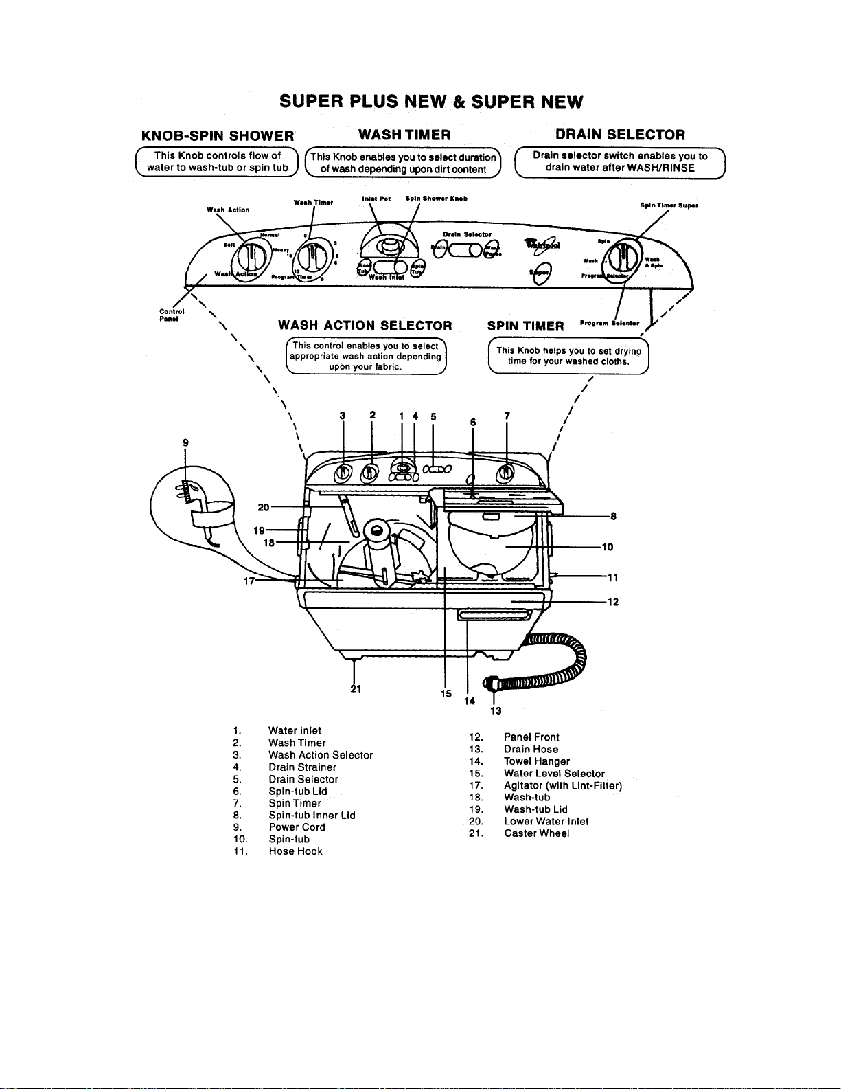
1.WASH TIMER
This Electro mechanical timer is meant for selecting the WASH / RINSE duration ranging
from 1 minute to 15 minutes. Indications for 3,6,9,12 & 15 minutes are given in the dial. For
setting the required duration, the knob has to be rotated in clockwise direction and set at
corresponding mark in the dial. Once the knob is set at the required position, the machine is
switched on and the timer automatically rewinds in anticlockwise direction while performing
WASH / RINSE. Once the timer knob reaches the 'OFF' position, the buzzer indicates the
completion of the cycle and the machine gets automatically switched off.
2 . WASH ACTION
Wash action switch is basically a three position switch viz., HEAVY, NORMAL, & SOFT.
This knob controls the ON and OFF duration of the motor during agitation thereby varying
the washing action. The following are the wash timing corresponding to various settings:
3. DRAIN SELECTOR
This is a mechanical, slide type knob with two positions WASH/RINSE and DRAIN. When
set at WASH/RINSE position, the drain valve attached to the wash tub is closed thereby
allowing the water to get retained in the tub to perform wash/rinse , If the knob Is pushed to
DRAIN mode , the drain and the water in the wash tub is drained out.
4. SPIN TIMER (only in SUPER PLUS NEW Model)
This is a mechanical, spring wound timer meant for setting the spin duration ranging form 1
to 5 minutes. For setting the required duration, the knob has to be rotated clockwise and set at
the required mark. Never attempt to rotate the timer in anticlockwise direction. Once the
knob is set at the required position, the spin motor starts rotating thereby completing the
drying process. Once the cycle is completed, the knob reaches OFF position and thereby the
supply to the spin motor is automatically cut off.
Since the spin timer is a spring wound type, in case of any power cut, the same will not be
sensed by the timer and it continues to rewind till it reaches the OF POSITION.
Doc No. WOI/washer/2001/009 Page No 8
Modified on date 03/08/2001 Subject to modification
Page 9

5. SPIN SHOWER
This is again a tow position knob viz. WASH TUB and SPIN SHOWER. When set at WASH
TUB position, it allows the water to be filled in the wash tub. When set at SPIN SHOWER
position, the water gets filled in the spin tub.
Spin shower option is generally used to aid the soap removal form the clothes. During this
process, the clothes are loaded in the spin tub and the knob is set at SPIN SHOWER mode.
Water is then filled into the machine. This water gets sprayed over the clothes in spintub.
After 2 minutes of spraying, the water supply needs to be cut off and then spin timer is set
ON for few minutes of spinning. This removes the suds from the clothes effectively.
6. PROGRAM SELECTTOR (applicable only for SUPER NEW model)
In super new models, the spin timer is replacing this three way switch. The three positions
available are WASH, SPIN and WASH & SPIN. This switch will work in conjunction with
the wash timer (Known as PROGRAM TIMER in SUPER NEW model) as detailed below:
AT WASH POSITION : The wash motor will be ON for the duration set at
PROGRAM TIMER
AT SPIN POSITON : The spin motor will be ON for the duration set at
PROGRAM TIMER
AT WASH & SPIN : BOTH THE WASH AND SPIN MOTORS will be ON for
the duration set at PROGRAM TIMER
Doc No. WOI/washer/2001/009 Page No 9
Modified on date 03/08/2001 Subject to modification
Page 10

POS_NO material PART_CODE DESCRIPTION
1 P013200160D P0132001516-0 LID WASH - APP. WHITE 1111 1
2 P013200040B P0132001504-0 WINDOW - LID WASH 111111
3 P013200170F P0132001517-0 LID SPIN - APP. WHITE 111111
4 P013200080C P0132001508-0 BRACKET - LID WASH - OFF WHITE 1 1 1
4 P013200280C P0132001528-0 BRACKET - LID WASH - APWH 1 1 1
5 P013200180D P0132001518-0 PANEL FRONT - APP. WHITE 111111
6 P010600020C P0106001502-0 INNER COVER-SPIN 111111
7 P014200010B P0142001501-0 SPIN CAP - PL/SS 111111
8 P010612290B P0106121529-0 FILTER CAP - APWH 111111
9 P010612350A P0106121535-0 COUPLING LINT FILTER - APWH 111111
10 P010612380A P0106120005-0 FILTER NET ASSY 111111
11 S011280120B S011280T 012-0 AGIT AT OR SCREW 111111
12 P010612320G P0106121532-0 AGITATOR - APWH 111111
13 P0132120300 P0132120003-0 BELLOW SPIN ASSY - TT 111111
14 P0106180200 P0106180006-0 DRUM COUPLING ASSY 111111
15 P010618250A P0106180901-0 BRAKE FIX PLATE 111111
16 P010618010H P0106181501-0 UNDER BASE 111111
17 P0132400200 P0132401502-0 DIVERTOR 111111
18 P013200310B P0132005702-0 SPRING LID 111111
19 P014213020B P0142131502-0 COVER - SPIN BASKET - PLASTIC 111111
20 P010613030E P0106130003-0 BALANCE RING ASSEMBLY (TT) 111111
21 P013513020D P0135131501-0 SPIN BASKET - PLASTIC 111111
22 P010613020R P0106130002-0 SHAFT FIX PLATE ASSY 111111
23 P010618040I P0106180004-0 BRAKE WIRE ASSY 111111
24 P013218040B P0132180901-0 PULLEY FAN - BOTTOM (BIG) 111111
24 P013218050B P0132180902-0 PULLEY FAN - TOP (SMALL) 111111
25 P010618240F P0106182503-0 MOTOR - WASH (30MM STACK) 1
25 P013818010F P0138182501-0 MOTOR - WASH - 110 ~ 127V, 60HZ 11111
26 P0106181601-0 P0106181601-0 GROMMET 333333
27 P0106181800 P0106181503-0 GROMMET SUPPORT PLATE 111111
28 P0106181502-0 P0106181502-0 WHEEL CASTOR 444444
28 P0106182800 P0106181502-0 W HEEL CASTOR 444444
29 P0136181200 P0136180701-0 WHEEL - SHAFT (LONG) 444444
30 P013240250D P0132401525-0 KNOB SLIDE SELECTOR - APP. WHITE 111111
31 P0132401300 P0132401513-0 RETAINER - SPIN SHOWER 111111
32 P0136700100 P0136700001-0 FILL HOSE ASSY - EXPORT 1 1111
33 P0106123700 P0106121602-0 O RING - TT 111111
With pump
With pump
With pump
110v
110v
110v
BCM58E0A
BDM58E5A
BDN58E0A
No pump
No pump
No pump
110v
110v
220v
BDH58E0A
BDL58E0A
BDI58E3A
Doc No. WOI/washer/2001/009 Page No 10
Modified on date 03/08/2001 Subject to modification
Page 11

POS_NO material PART_CODE DESCRIPTION
34 P010612010C P0106121601-0 RUBBER RING 111111
35 P0132170000 P0132170000-0 DRIVE ASSY 111111
36 P013212070C P0132121502-0 PULLEY - DRIVEN 111111
37 S011590010A S011590T 001-0 NUT (NYLOC) 111111
38 P010612330C P0106121533-0 LOWER WATER INLET - APWH 111111
41 P010618050A P0106181505-0 BAND-BRAKE 111111
42 P0132180300 P0132180003-0 CUSH MOTOR ASSY - TT 333333
43 P010618190C P0106182801-0 DUAL CAPACITOR - (1O+5 MFD) 1
43 P0138180700 P0138182801-0 DUAL CAPACITOR - (40+15 MFD) 1
43 P0138180800 P0138182802-0 DUAL CAPACITOR - (40+20MFD) 1 1 1 1
44 P013240120F P0132401512-0 BRACKET - TIMER STRIGHT 111111
46 P013240270F P0132401527-0 KNOB SLIDE DRAIN - APP. WHITE 111111
47 P013240140B P0132401514-0 HOUSING - CONTROL LEVER (EXPORT) 1 1 1
48 P013240240G P0132401524-0 KNOB ROTARY - A - APP. WHITE 222222
49 P013240280G P0132401528-0 CONTROL PANEL - SUPER + - APP. WHITE 1 1 1 1
49 P013840060G P0138401506-0 CONTROL PANEL - APWH-MEXICO-WHIRLPOOL 1 1
50 P013240050A P0132400005-0 SPIN TIMER ASSY- S(3A)-TANGO 111111
51 P013200060D P0132001506-0 COVER - SPLASH - NATURAL 1 1 1
51 P013200260D P0132001526-0 COVER - SPLASH - APWH 1 1 1
52 P013240550B P0132402702-0 ROTARY SWITCH - WASH (SUPER PLUS) 1
52 P013840010A P0138402701-0 ROTARY SWITCH - WASH - 127V, 60HZ 11111
53 P010600060C P0106001506-0 RETAINER-BRAKE WIRE 111111
54 P0106125300 P0106121606-0 COUNTER FLOW PROTECTOR 111111
55 P010612260I P0106121526-0 TUB - APWH 111111
56 P010600530B P0106001601-0 V-BELT(T WIN TUB) 111111
57 S017100000A S017100T000-0 PIG TAIL CONNECTOR-3 DIA 888888
58 S0171000100 S017100T001-0 PIG TAIL CONNECTOR-3.8 DIA 2 2 2
58 S0171000100 S0171000001-0 PIG TAIL CONNECTOR-3.8 DIA 2 2 2
59 P013240100A P0132400010-0 MICRO SWITCH ASSY - TT 111111
60 P011050030A P0110502703-0 SWITCH - KICKOUT (3 TERMINAL + LEVER) 1 1 1
61 P0106125100 P0106120002-0 DRAIN ASSY 111111
62 P010612500D P0106121507-0 VALVE CAP 111111
63 P010612460C P0106125701-0 VALVE SPRING 111111
64 P0106122000 P0106121520-0 VALVE ROD-ADJUSTABLE 111111
65 P010612050A P0106121605- 0 BELLOW S-VALVE 111111
66 P010612450D P0106125101-0 HOSE-TUB TO DRAIN (D:36, L:275) 111111
67 P010612040G P0106121504-0 INLET JOINT 111111
With pump
With pump
With pump
110v
110v
110v
BCM58E0A
BDM58E5A
BDN58E0A
No pump
No pump
No pump
110v
110v
220v
BDH58E0A
BDL58E0A
BDI58E3A
Doc No. WOI/washer/2001/009 Page No 11
Modified on date 03/08/2001 Subject to modification
Page 12

POS_NO material PART_CODE DESCRIPTION
68 P010612520E P0106121505-0 VALVE HOUSING 111111
69 P013200250C P0132001525-0 BASE WATER PASSAGE - APWH 111111
70 P013200010I P0132000901- 0 BRACKET-BRAKE WIRE 111111
71 P010612280D P0106121528-0 COVER SLIDER - APWH 111111
72 P014212020D P0142121502-0 SLIDER - ADJ. OVERFLOW - APWH 111111
73 P010612470F P0106125102-0 HOSE-ADJUSTABLE OVERFLOW 111111
74 P010612300A P0106121530-0 STRAINER - APWH 111111
75 P010612310B P0106121531-0 STRAINER BRACKET - APWH 111111
76 P0142000700 P0142001507-0 INSPECTION COVER - HIPS - APWH 111111
77 P010612070D P0106120007-0 INNER EARTH ASSY 1 1 1
77 P0136180500 P0136182605-0 INNER EARTH - WMOTOR JT / SM JT. - 300L 111111
78 P013240570B P0132400006-0 FUSE ASSY (3A) - TT 1
78 P013840080A P0138400008-0 FUSE ASSY - 6.3A/240V - SCREW TYPE 11111
79 P0136400500 P0136402802-0 POWER CORD - 2FLAT PIN-ONE ROUND PIN 111111
80 P0136180100 P0106125104-0 DRAIN HOSE 1 1 1
80 P0136180100 P0136185101-0 DRAIN HOSE - EXPORT 1 1 1
81 P013621050G P0136211001-0 CABINET - APP. WHITE - EXPORTS 1111 1
82 P010612340D P0106121534-0 OVERFLOW FILTER - APWH 111111
83 P0106182600 P0106185701-0 STRING-BRAKE 111111
84 P013200270C P0132001527-0 TOP PLATE - APWH 111111
85 P010618220D P0106182504-0 MOTOR SPIN -20MM 1
85 P013818020D P0138182502-0 MOTOR - SPIN - 110 ~ 127V, 60HZ 11111
86 P013240260K P0132401526-0 KNOB ROTARY - C - APP. WHITE 111111
P010640030B P0106401803-0 DRAIN CABLE - STEEL 1 1 1
P010690150A P0106900015-0 LINT FILTER ASSY - APWH 111111
P011050030A P0110502703-0 SWITCH - KICKOUT (3 TERMINAL + LEVER) 1 1 1
P0115900100 P0115906501-0 CUSHION-UNDER 111111
P011590080A P0115901501-0 DRAIN BEND - EXPORT 1 1 1
P012112010B P0121125101-0 HOSE-VALVE HOUSING TO PUMP (D-36, L275) 1 1 1
P0121180100 P0121180901-0 BRACKET - PUMP 1 1 1
P012140010B P0121400901-0 SPRING PLATE - DRAIN SWITCH 1 1 1
P0132120600 P0132121002-0 HOOK - VALVE ROD 1 1 1
P0132120600 P0142121001-0 HOOK - VALVE ROD 1 1 1
P013240040D P0132401504-0 HOUSING - LEVER CONTROL 1 1 1
P0132400700 P0132400007-0 DRAIN CONTROL ASSY 111111
P013240490B P0132401506-0 BRACKET - ROTARY SWITCH 111111
With pump
With pump
With pump
110v
110v
110v
BCM58E0A
BDM58E5A
BDN58E0A
No pump
No pump
No pump
110v
110v
220v
BDH58E0A
BDL58E0A
BDI58E3A
Doc No. WOI/washer/2001/009 Page No 12
Modified on date 03/08/2001 Subject to modification
Page 13

POS_NO material PART_CODE DESCRIPTION
P013290010E P0132906501-0 CUSHION - TOP 111111
P0132900300 P0132906503-0 TOP COVER - EDGE 222222
P0132900400 P0132906504-0 TOP COVER - MIDDLE 111111
P013290050B P0132906505-0 CUSHION - MIDDLE 111111
P0138220100 P0138220001-0 PUMP ASSEMBLY - 127V - 60HZ 1 1 1
P013890080B P0138906502-0 BOX PACKING - SRILANKA 111111
P0142400900 P0142401509-0 BRACKET - MICRO SWITCH 111111
With pump
With pump
With pump
110v
110v
110v
BCM58E0A
BDM58E5A
BDN58E0A
No pump
No pump
No pump
110v
110v
220v
BDH58E0A
BDL58E0A
BDI58E3A
Doc No. WOI/washer/2001/009 Page No 13
Modified on date 03/08/2001 Subject to modification
Page 14

Doc No. WOI/washer/2001/009 Page No 14
Modified on date 03/08/2001 Subject to modification
Page 15

Doc No. WOI/washer/2001/009 Page No 15
Modified on date 03/08/2001 Subject to modification
Page 16

Doc No. WOI/washer/2001/009 Page No 16
Modified on date 03/08/2001 Subject to modification
Page 17

Trouble shooting chart
S.NO PROBLEM POSSIBLE CAUSE REMEDY
1 Shock/Current Leak Earth Not Proper Connect Proper
Earthing
2 Machine Not Functioning No Supply At The Power Point Check Electrical
Supply At Socket
Plug Switch Is Not On Switch On The Plug
Blown Up Fuse Replace Fuse
Defective Power Cord Refer CCG *
Defective Wash Timer Refer CCG
Defective Capacitor Refer CCG
Defective Drive Assy Refer CCG
Defective Drive Belt Replace
3 No Drain Drain Hose Hooked On Place The Drain Hose
Machine At Ground Level
Kinked / Clogged Drain Hose Remove / Clean
Drain Valve Control Wire Reconnect Drain
Dislodged Wire
Control Cable Cut Replace Cable
Clogged Drain Valve Clean Drain Valve
4 No Agitation Wash Timer Defective Refer CCG
Wash Motor Defective Refer CCG
Drive Belt Cut Replace Drive Belt
Defective Drive Assy Refer CCG
Defective Capacitor Refer CCG
Wire Discontinuity Rectify
5 One Side Agitation Defective Wash Timer Refer CCG
Defective Wash Motor Refer CCG
Defective Drive Assy Refer CCG
6 Noisy Agitation Loose Drive Belt Adjust
Defective Drive Assy Refer CCG
Loose Agitator Fix The Agitator
Proper ly
Defective Wash Motor Refer CCG
7 Leak During Drain Defective Drain Valve Refer CCG
Punctured Drain Hose Replace
8 No Spin Lid Open Close Lid
Defective Lid Switch Replace
Defective Capacitor Refer CCG
Defective Spin Motor Refer CCG
Improper Brake Adjust
Defective Brake Cable Replace
9 Noisy Spin Defective Spin Basket Replace
Loose Coupling Bolt Tighten
Loose Basket Shaft Tighten
Defective Spin Motor Refer CCG
* CCG is the Component Check Guide table in the next page
Doc No. WOI/washer/2001/009 Page No 17
Modified on date 03/08/2001 Subject to modification
Page 18

COMPONENT CHECK GUIDE
S.NO COMPONENT NATURE OF TESTING PROCEDURE REMEDY
PROBLEM
1 Machine Gives Check for proper earthing to Inform customer
shock which the machine is connected to correct for
using multimeter. proper earthing
Check voltage between
Phase & Neutral
Phase & Earth
both should be equal.
Check continuity between
Neutral & Earth
If found to be short Earthing is
defective
2 Fuse Blown Using multimeter check continuity
between both the ends.
Replace the fuse
3 Power cord Discontinuity Check for proper continuity
between plug side and machine
side also check for short circuit
between wires
4 capacitor Not functioning
WARNING
DISCHARGE
BEFORE
HANDLING
5 Wash Motor Does not run Check the winding resistance
6 Spin Motor Does not run Check the winding resistance
Check the capacitor with the
multimeter in continuity mode.
The meter should first read ohms
and gradually the needle should
swing back to infinity Ohms. It
indicates a good capacitor and
any thing other than this is
defective.
using a multimeter between wires
BLACK & BLUE 37.6 Ohms
approx. BLACK & YELLOW 42.6
Ohms. If the resistances are not
as per the given value it could be
short or open
using a multimeter between wires
BLACK & BROWN 69 Ohms
approx. BLACK & WHITE 77.5
Ohms. If the resistances are not
as per the given value it could be
short or open
Replace power
cord
Replace the
capacitor
Replace the wash
motor
Replace the Spin
motor
Doc No. WOI/washer/2001/009 Page No 18
Modified on date 03/08/2001 Subject to modification
Page 19

COMPONENT CHECK GUIDE
7 Wash / Spin
motor
Electric current
8 Timer No spin Check continuity between the
1. In OFF position the meter should read infinit
2. In ON position the meter should read zero Ohms.
Noisy Operation
Wash / Spin
leakage
Visually check the damages on
pulley and refer, also check for
free rotation of the rotor. If any
damages noticed or the rotor not
rotating freely indicates defective
motor (Wash & Spin).
Check the motors for short
between body and terminals
using a multimeter. If meter
shows continuity, it indicates
motor is defective.
terminals of the spin timer using a
multimeter.
resistance.
Cont’d
Replace the
Wash / Spin
motor.
Replace the
motor.
Replace the spin
timer
If the meter not showing as per above statements it
indicates defective spin timer
Not advancing Set the Timer to one position and
check the knob whether coming
back to OFF position. If not
coming indicates defective spin
timer.
9 Wash Timer Not advancing /
No Wash
11 Circuit breaker No spin Adjust / Replace the circuit
12 Drive assy Noisy agitation Visually check for excessive play
Set the timer to one position and
check the knob whether coming
back to OFF position after
switching On the machine. If not
coming indicates defective wash
timer
breaker and check for the
continuity using a multimeter. If
no continuity indicates circuit
breaker defective.
in the shaft. If anything as above
noticed indicates defective drive
assy.
Replace the spin
timer.
Replace the wash
timer.
Make contact
between the two
leads to the
circuit breaker
assy.
Replace the drive
assy
Doc No. WOI/washer/2001/009 Page No 19
Modified on date 03/08/2001 Subject to modification
 Loading...