

Whirlpool WVU31UC0FB, WVU31UC0FS, WVU31UC0FW, WVU31UC6FB, WVU31UC6FS Use & Care Guide
...
30" (76.2 CM) AND 36" (91.4 CM)
IMPORTANT: READ AND SAVE THESE INSTRUCTIONS.
FOR RESIDENTIAL USE ONL
IMPOR
POUR UTILISA
.
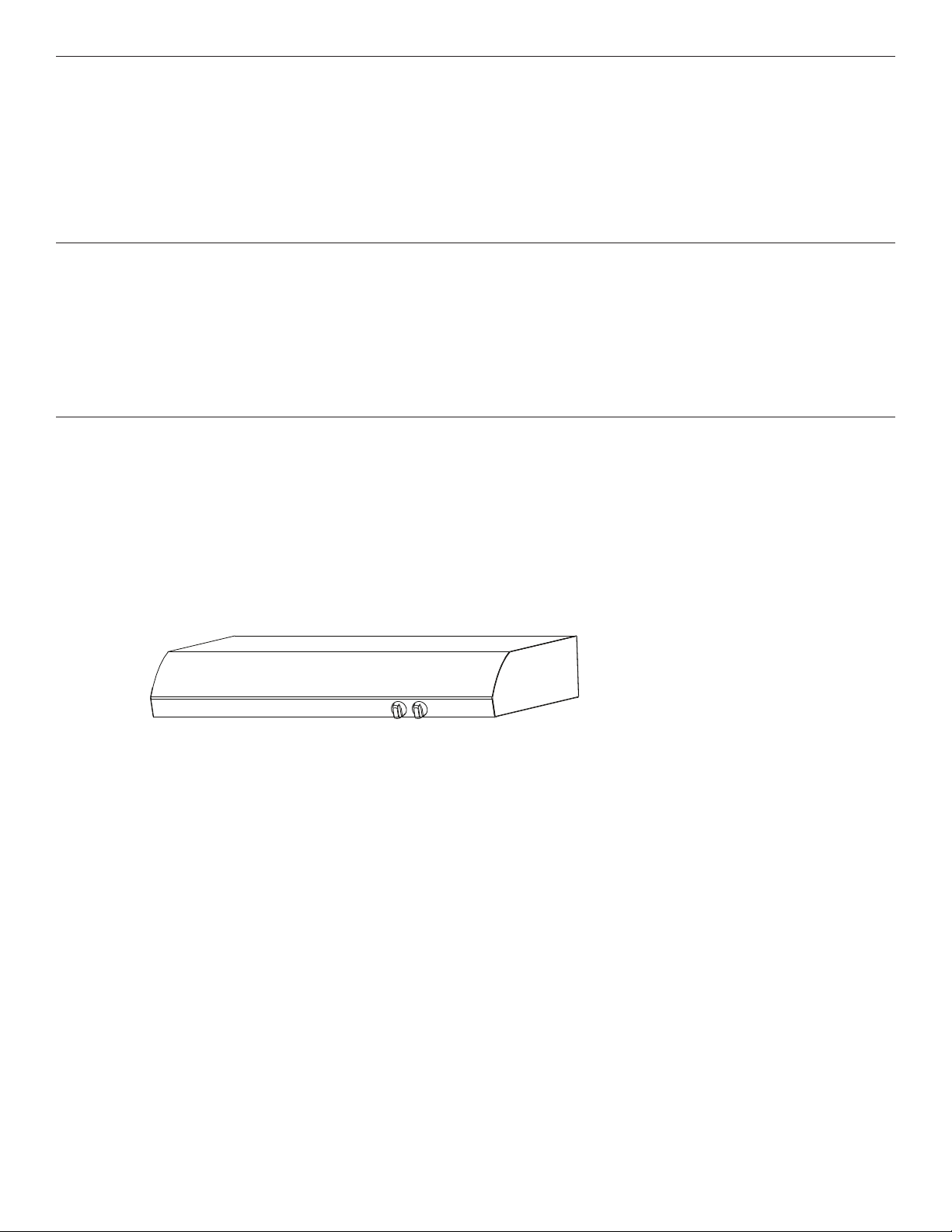
RANGE HOOD
Installation Instructions and Use & Care Guide
For questions about features, operation/performance, parts, accessories or service,
call: 1-800-253-1301 or visit our website at www.whirlpool.com
In Canada, call 1-800-807-6777 or visit our website at www.whirlpool.ca
HOTTE D’ASPIRATION DE 30" (76.2 CM) ET
36" (91.4 CM)
Instructions d’installation et Guide d’utilisation et d’entretien
Au Canada, pour assistance, installation ou service, composer le 1-800-807-6777 ou visiter notre site Web à www.whirlpool.ca
Table of Contents/Table des matières .....................................2
Models/Modèles:
WVU31UC0F/WVU31UC6F
Y.
TANT : LIRE ET CONSERVER CES INSTRUCTIONS.
LI32AC/W10907093A
TION RÉSIDENTIELLE UNIQUEMENT
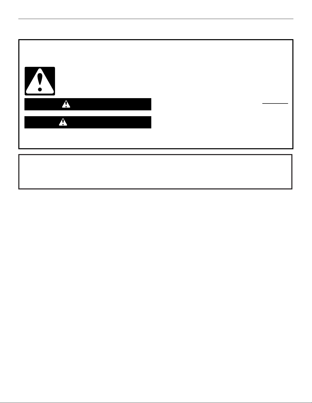
IMPORTANT SAFETY INSTRUCTIONS
READ AND SAVE THESE INSTRUCTIONS
RANGE HOOD SAFETY
Your safety and the safety of others are very important.
We have provided many important safety messages in this manual and on your appliance. Always read and obey all safety
messages.
This is the safety alert symbol.
This symbol alerts you to potential hazards that can kill or hurt you and others.
All safety messages will follow the safety alert symbol and either the word “DANGER” or “WARNING.”
These words mean:
You can be killed or seriously injured if you don't immediately
DANGER
WARNING
All safety messages will tell you what the potential hazard is, tell you how to reduce the chance of injury, and tell you what can
happen if the instructions are not followed.
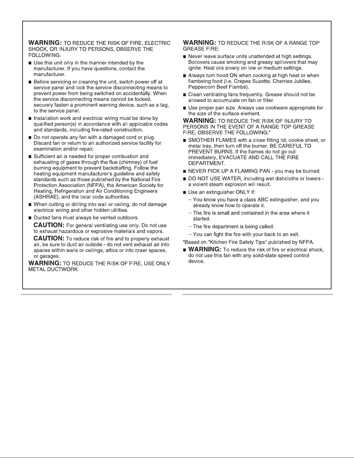
State of California Proposition 65 Warnings:
WARNING: This product contains one or more chemicals known to the State of California to cause cancer.
WARNING: This product contains one or more chemicals known to the State of California to cause birth defects or other
reproductive harm.
follow instructions.
You
can be killed or seriously injured if you don't
instructions.
follow
2
IMPORTANT SAFETY INSTRUCTIONS
READ AND SAVE THESE INSTRUCTIONS
TABLE OF CONTENTS TABLE DES MATIÈRES
RANGE HOOD SAFETY .................................................................2
INSTALLATION REQUIREMENTS .................................................4
Tools and Parts .............................................................................4
Location Requirements ................................................................4
Venting System ............................................................................5
Electrical Requirements ...............................................................6
INSTALLATION INSTRUCTIONS ...................................................7
RANGE HOOD USE ......................................................................11
Range Hood Controls ................................................................11
RANGE HOOD CARE ...................................................................12
Cleaning .....................................................................................12
WIRING DIAGRAM .......................................................................13
ASSISTANCE OR SERVICE .........................................................14
In the U.S.A. ...............................................................................14
In Canada ...................................................................................14
WARRANTY ..................................................................................15
SÉCURITÉ DE LA HOTTE DE CUISINIÈRE ...............................16
EXIGENCES D’INSTALLATION ...................................................18
Outillage et pièces ......................................................................18
Exigences d’emplacement .........................................................18
Circuit d’évacuation ...................................................................19
Spécifications électriques ..........................................................21
INSTRUCTIONS D’INSTALLATION .............................................22
UTILISATION DE LA HOTTE .......................................................26
Commandes de la hotte de cuisinière .......................................26
ENTRETIEN DE LA HOTTE .........................................................27
Nettoyage ...................................................................................27
SCHÉMA DE CÂBLAGE ...............................................................28
ASSISTANCE OU SERVICE .........................................................29
Au Canada ..................................................................................29
GARANTIE .....................................................................................30
3
INSTALLATION REQUIREMENTS
(2.5 cm)
(12.5 cm)
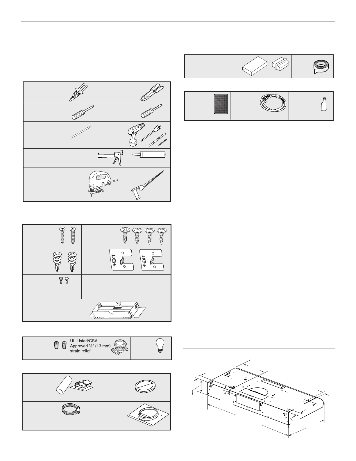
Tools and Parts
Gather the required tools and parts before starting
installation. Read and follow the instructions provided
with any tools listed here.
Tools needed
Metal snips
#2 Phillips
screwdriver
Pencil
Caulking gun and weatherproof
caulking compound
Jigsaw or keyhole saw
Parts supplied
Remove parts from package. Check that all parts are included.
#8-18 x 1"
(4.2 x 25 mm)
flat-head screws
Drywall
anchors
Short Phillips
head screws
Wire stripper
Flat-blade
screwdriver
Drill with ¹⁄₈"
(3 mm), ¹⁄₂"
(13 mm)
and 1¹⁄₄"
(3 cm) bits
#8-18 x ⁵⁄₈"
(4.2 x 16 mm)
truss-head screws
Mounting
brackets
For 31/4" x 10" (8.3 x 25.4 cm) rectangular vented
installations
3¹⁄₄" x 10"
(8.3 x 25.4 cm) rectangular
metal vent system with
wall or roof cap
Duct tape
Optional accessories
Charcoal
filter kit
Part Number
W10355450*
Power
cord kit
Part Number
W10355452*
* For information on ordering, see the “Assistance or Service”
section.
Stainless steel
cleaner and
polish
Part Number
31462A*
Location Requirements
IMPORTANT: Observe all governing codes and ordinances.
■ It is the installer’s responsibility to comply with installation
clearances specified on the model/serial/rating plate.
The model/serial/rating plate is located inside the range
hood on the left wall.
■ Range hood location should be away from strong draft
areas, such as windows, doors, and strong heating vents.
■ Cabinet opening dimensions that are shown must be
used. Given dimensions provide minimum clearance.
Consult the cooktop/range manufacturer installation
instructions before making any cutouts.
■ This range hood is recommended for use with cooktops
with a maximum total rating of 40,000 Btus or less.
■ Grounded electrical outlet is required. See the “Electrical
Requirements” section.
■ All openings in ceiling and wall where range hood will
be installed must be sealed.
■ These range hoods are factory set for vented installations.
Models that are capable of being installed as non-vented
(recirculating) require charcoal filters. See the “Assistance or
Service” section for information on ordering charcoal filters.
3¹⁄₄" x 10" (8.3 x 25.4 cm)
rectangular damper
Parts needed
UL Listed/CSA
Approved
wire connectors
120V, 75W
maximum,
type E26
lamp
For 7" (17.8 cm) round vented installations
7" (17.8 cm)
round
metal vent
system with
wall or roof cap
Vent clamps as
required
4
7" (17.8 cm)
round damper
Part Number
W10355451*
7" (17.8 cm)
round vent
mounting plate
Part Number
W10388168*
For Mobile Home Installations
The installation of this range hood must conform to the
Manufactured Home Construction Safety Standards, Title
24 CFR, Part 328 (formerly the Federal Standard for Mobile
Home Construction and Safety, title 24, HUD, Part 280)
or when such standard is not applicable, the standard for
Manufactured Home Installation 1982 (Manufactured Home
Sites, Communities, and Setups) ANSI A225.1/NFPA 501A,
or latest edition, or with local codes.
Product Dimensions
6⁹⁄₁₆" (16.7 cm) or
4¹⁵⁄₁₆"
2"
(5.1 cm)
(2.2 cm)
⁷⁄₈"
9⁹⁄₁₆" (24.4 cm)
29¹⁵⁄₁₆" (76.0 cm) or
35¹⁵⁄₁₆" (91.0 cm)
9"
(22.9 cm)
1¹⁄₂"
(3.8 cm)
18⁵⁄₈"
(47.3 cm)
1"
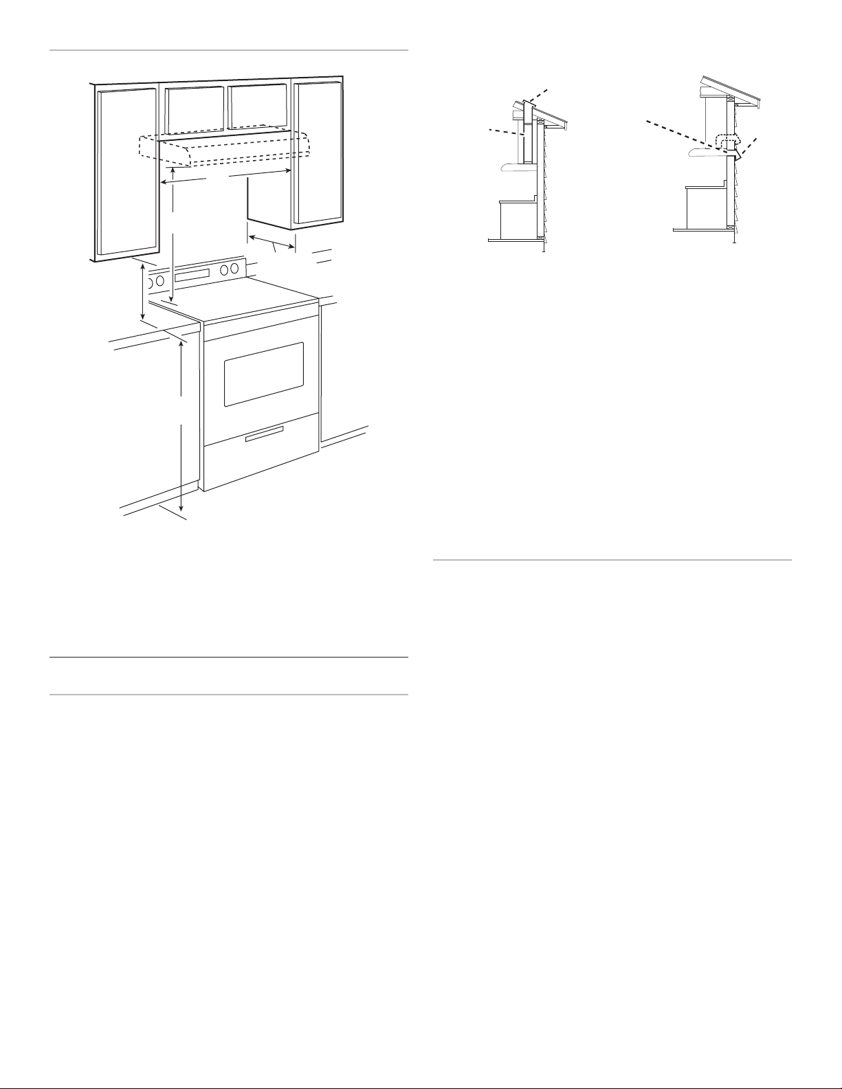
Installation Clearances
A
B
A
B
A
Top Venting Wall Venting
C
D
B
E
A. 24" (61 cm) minimum distance from electric cooking surface
24" (61 cm) minimum distance from gas cooking surface
30" (76.2 cm) suggested maximum above the cooking surface
B. 18" (45.7 cm) minimum clearance - upper cabinet to countertop
C. 30" (76.2 cm) minimum cabinet opening width for 30" (76.2 cm)
model
36" (91.4 cm) minimum cabinet width for 36" (91.4 cm) models
D. 12" (30.5 cm) cabinet depth
E. 36" (91.4 cm) base cabinet height
Venting System
Venting Methods
NOTES:
■ A flexible vent is not recommended. Flexible vent
creates both back pressure and air turbulence
that greatly reduce performance.
■ The vent system is optional for this model.
Vent system can terminate either through the roof or wall. Use
31/4" x 10" (8.3 x 25.4 cm) rectangular with a maximum vent
length of 35 ft (10.7 m) or 7" (17.8 cm) or larger round vent with a
maximum length of 50 ft (15.2 m) for vent system.
A. 7" (17.8 cm) round vent or
31/4" x 10" (8.3 x 25.4 cm)
rectangular vent through roof
(purchased separately)
B. Roof cap with damper
(purchased separately)
A. 7" (17.8 cm) round vent or
31/4" x 10" (8.3 x 25.4 cm)
rectangular vent through wall
(purchased separately)
B. Wall cap with damper
(purchased separately)
Cold Weather Installations
An additional back draft damper should be installed to
minimize backward cold air flow and a thermal break should
be installed to minimize conduction of outside temperatures
as part of the vent system. The damper should be on the cold
air side of the thermal break.
The break should be as close as possible to where the
vent system enters the heated portion of the house.
Makeup Air
Local building codes may require the use of makeup
air systems when using ventilation systems greater than
specified CFM of air movement. The specified CFM varies
from locale to locale. Consult your HVAC professional
for specific requirements in your area.
Venting Requirements
■ Vent system must terminate to the outdoors, except for
nonvented (recirculating) installations.
■ Do not terminate the vent system in an attic
or other enclosed area.
■ Do not use a 4" (10.2 cm) laundry-type wall cap.
■ Use 7" (17.8 cm) round metal vent or 3
x 25.4 cm) rectangular metal vent, depending on your
installation requirement. Rigid metal vent is recommended.
Plastic or metal foil vent is not recommended.
■ The length of vent system and number of elbows should
be kept to a minimum to provide efficient performance.
For the most efficient and quiet operation:
■ Use no more than three 90° elbows.
■ Make sure there is a minimum of 24" (61 cm) of straight
vent between the elbows if more than 1 elbow is used.
■ Do not install 2 elbows together.
■ Use clamps or duct tape to seal all joints in the vent system.
■ The vent system must have a damper. If roof or wall cap has
a damper, do not use damper supplied with the range hood.
■ Use caulking to seal exterior wall or roof opening
around the cap.
1
/4" x 10" (8.3
5
Calculating Vent System Length
Wall cap
90˚ elbo
To calculate the length of the system you need, add the
equivalent feet (meters) for each vent piece used in the system.
Vent System
Vent Piece
45° elbow 2.5 ft (0.8 m)
90° elbow 5 ft (1.5 m)
31/4" x 10" (8.3 cm x
12 ft (3.7 m)
25.4 cm) flat elbow
7" (17.8 cm) wall cap 0 ft (0 m)
31/4" x 10" (8.3 cm
4.5 ft (1.4 m)
x 25.4 cm) to
7" (17.8 cm)
31/4" x 10" (8.3 cm
5 ft (1.5 m)
x 25.4 cm) to
7" (17.8 cm)
90° elbow
Example vent system
w
6 ft (1.8 m)
Electrical Requirements
Observe all governing codes and ordinances.
Ensure that the electrical installation is adequate and in
conformance with National Electrical Code, ANSI/NFPA
70 (latest edition), or CSA Standards C22.1-94, Canadian
Electrical Code, Part 1 and C22.2 No. 0-M91 (latest edition)
and all local codes and ordinances.
If codes permit and a separate ground wire is used, it is
recommended that a qualified electrician determine that
the ground path is adequate.
A copy of the above code standards can be obtained from:
National Fire Protection Association
1 Batterymarch Park
Quincy, MA 02169-7471
CSA International
8501 East Pleasant Valley Road
Cleveland, OH 44131-5575
■ A 120-volt, 60 Hz., AC-only, 15-amp, fused
electrical circuit is required.
■ If the house has aluminum wiring, follow
the procedure below:
1. Connect a section of solid copper wire
to the pigtail leads.
2. Connect the aluminum wiring to the added section
of copper wire using special connectors and/or tools
designed and UL Listed for joining copper to aluminum.
Follow the electrical connector manufacturer’s recommended
procedure. Aluminum/copper connection must conform
with local codes and industry accepted wiring practices.
■ Wire sizes and connections must conform with the rating
of the appliance as specified on the model/serial/rating
plate. The model/serial/rating plate is located inside the
range hood on the left wall.
■ Wire sizes must conform to the requirements of the National
Electrical Code, ANSI/NFPA 70 (latest edition), or CSA
Standards C22. 1-94, Canadian Electrical Code, Part 1
and C22.2 No. 0-M91 (latest edition) and all local codes
and ordinances.
2 ft (0.6 m)
1 - 90° elbow = 5 ft (1.5 m)
1 - wall cap = 0 ft (0 m)
8 ft (2.4 m) straight = 8 ft (2.4 m)
System length = 13 ft (3.9 m)
Maximum Recommended Length
7" (17.8 cm) Round Vent = 50 ft (15.2 m)
31/4" x 10" (8.3 x 25.4 cm)
= 35 ft (10.7 m)
Rectangular Vent
6
INSTALLATION INSTRUCTIONS
NOTES:
■ Depending on your model, determine which venting
method to use: roof, wall, or non-vented (recirculating).
■ It is recommended that the vent system be installed before
the range hood is installed. Go to “Venting System” in the
“Installation Requirements” section if you need assistance.
■ Before making cutouts, make sure there is proper clearance
within the ceiling or wall for the vent system.
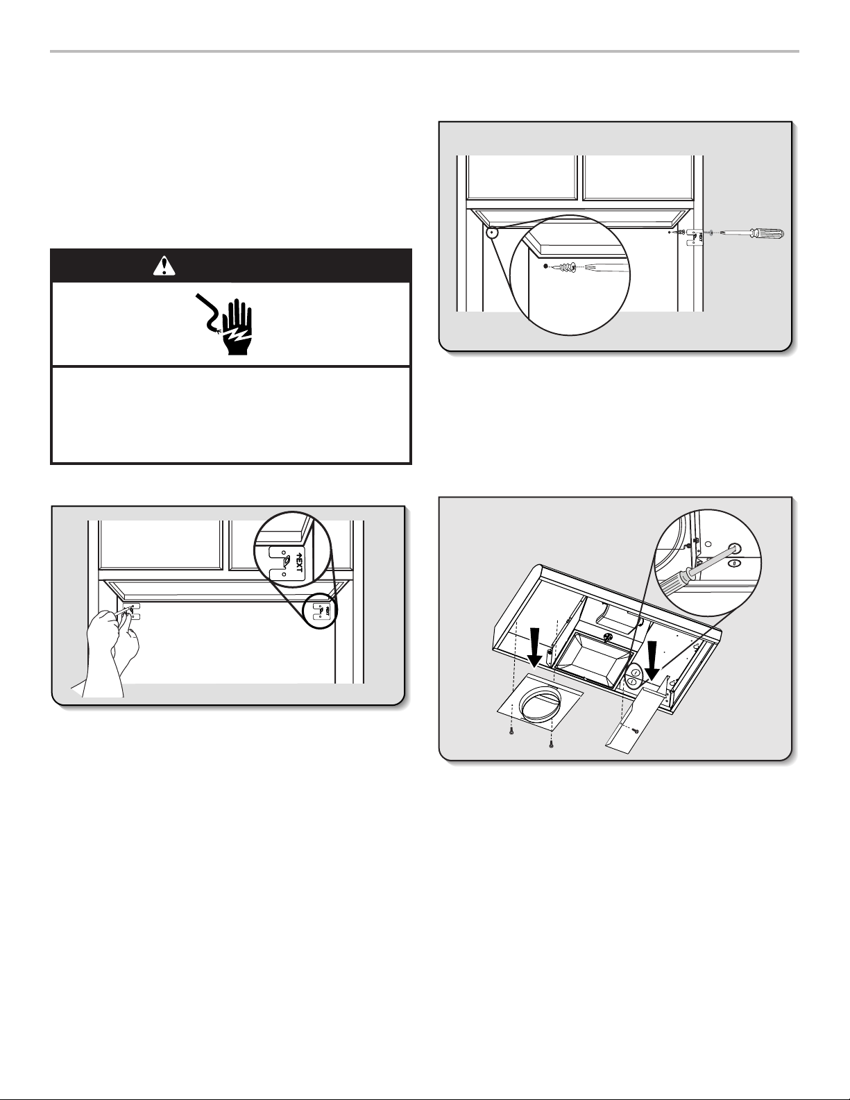
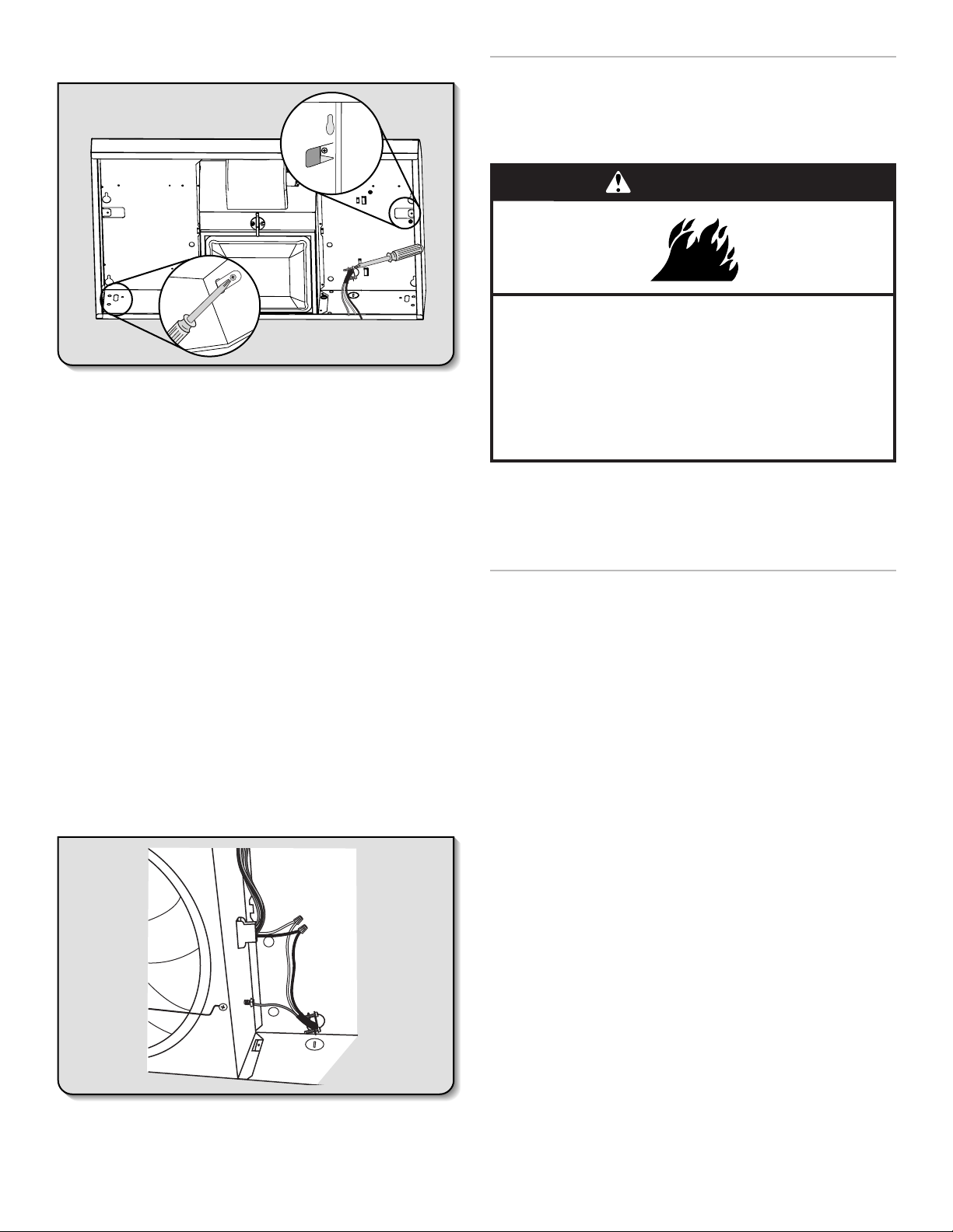
1. Disconnect power
WARNING
3. Install Brackets
Electrical Shock Hazard
Disconnect power before servicing.
Replace all parts and panels before operating.
Failure to do so can result in death or electrical shock.
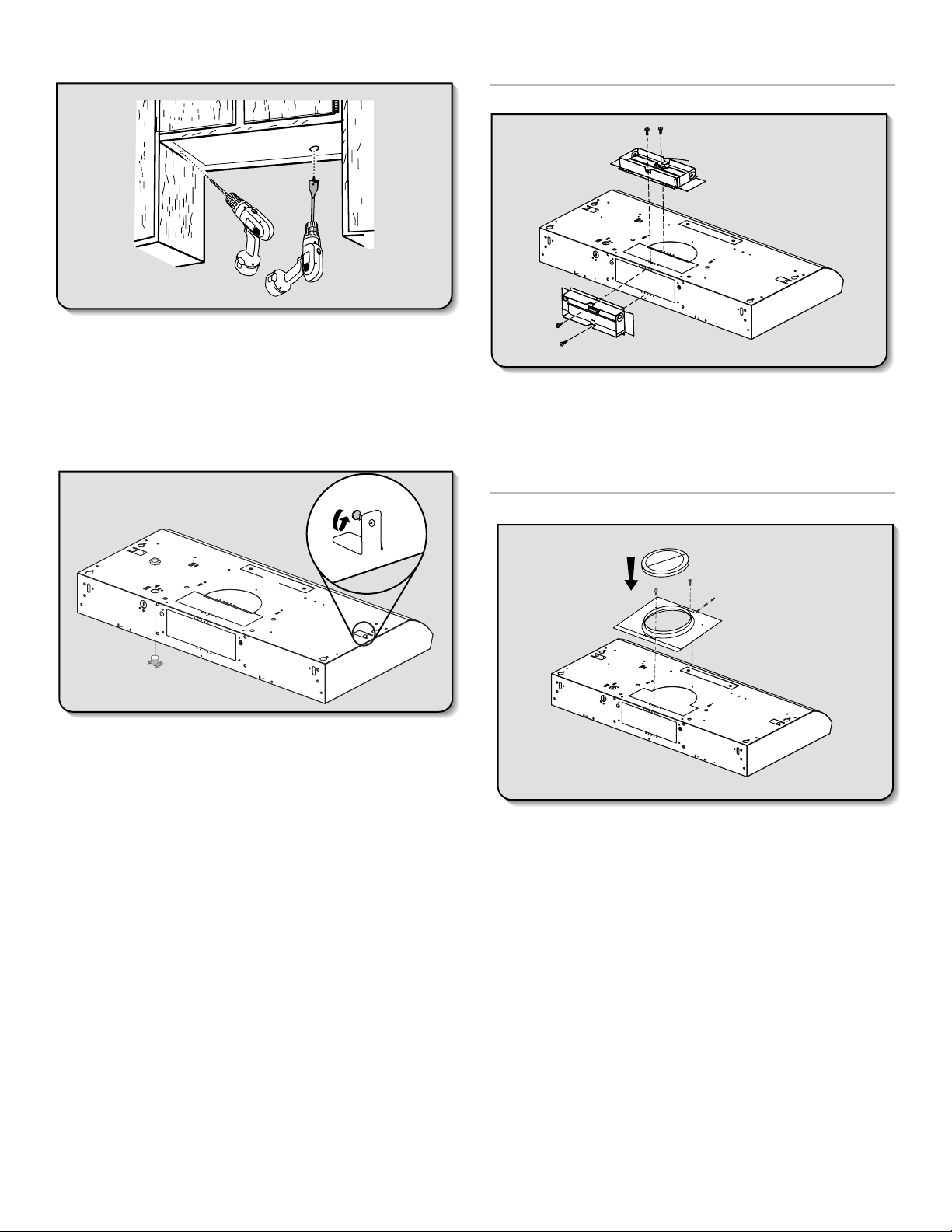
2. Mark Hole Locations
Align the exterior edge of the mounting brackets
with the exterior edges of the upper cabinet.
IMPORTANT: The brackets should touch the upper cabinet.
With a pencil, mark the upper holes on the brackets.
■ Using a #2 Phillips screwdriver, install the drywall anchors.
■ Using #8-18 x 1" (4.2 x 25 mm) flat-head #2 Phillips screws,
install the mounting brackets using the upper holes.
NOTE: For installations to a surface other than drywall,
it is recommended that a qualified contractor determine
the anchoring method.
4. Prepare Range Hood
■ Set the range hood on its back on a covered surface.
■ Depending on your vent system, use a #2 Phillips
screwdriver to remove the 7" (17.8 cm) round vent mounting
plate or the rectangular damper attached with 3.5 x 9.5 mm
screws.
■ Using a #2 Phillips screwdriver, remove the electrical
box cover.
■ Using a flat-blade screwdriver, remove the appropriate
power supply knockout.
7
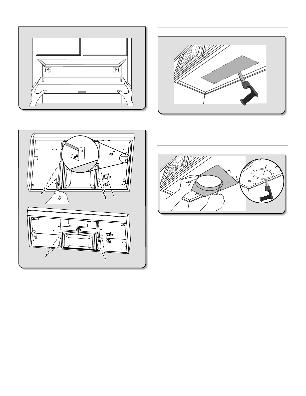
5. Mark Hole Locations
6. Mark and Cut Vent Opening
31/4" x 10" (8.3 x 25.4 cm) Rectangular Vent System
Lift the range hood into place and insert the mounting bracket
tabs through the slots in the back of the range hood.
A
A
45˚+
90˚
C
D
B
C
D
Hold the range hood firmly in place with one hand and
bend each mounting tab (A) upward approximately 90°.
Mark the hole at the power supply knockout (B).
For a non-vented (recirculating) installation: Go to Step 7.
For a top-vented installation: Mark the 4 vent hole locations (C)
on the top of the range hood.
For a rear-vented installation: Mark the 4 vent hole locations
(D) on the rear of the range hood.
OPTIONAL: Mark the hole in each mounting tab.
Remove the range hood and set it aside.
■ Using a
1
/2" (13 mm) drill bit, drill a hole in each of the dots
marked previously on either the wall or upper cabinet. Using
the outside edges of the holes, mark the vent opening.
■ Using a jigsaw or keyhole saw, cut the vent opening.
7" (17.8 cm) Round Vent System
1"
(2.5 cm)
A
■ Using the 7" (17.8 cm) round vent mounting plate, draw
the vent opening outline on the underside of the cabinet:
- Place the vent mounting plate on the bottom of the
cabinet. Position the edge of the plate with the widest
distance (A) between the hole and edge of the mounting
plate against the wall. Position the side edges of the
mounting plate between the dots marked previously.
IMPORTANT: The widest edge (A) of the vent
mounting plate must be positioned against the wall.
- Trace the 7" (17.8 cm) vent opening (solid line)
on the cabinet bottom.
■ Using a jigsaw or keyhole saw, cut the vent opening
1" (2.5 cm) larger than the 7" (17.8 cm) hole traced
(dashed line).
8
7. Drill Electrical Opening
Using a 11/4" (3 cm) drill bit, drill the hole in the dot
marked previously at the electrical strain relief.
OPTIONAL: Using a 1/8" (3 mm) drill bit, drill pilot holes
for the dots marked previously at each mounting tab
at an approximate 45° angle in an upward direction.
8. Prepare Range Hood Vents
and Mounting Tabs
F
x2
9. Attach Vent Damper or Transition
31/4" x 10" (8.3 x 25.4 cm) Rectangular Vent Damper
■ Using (2) short Phillips head screws, install the 3
(8.3 x 25.4 cm) rectangular damper over the top or rear vent
knockout removed in Step 8.
NOTE: If the wall cap used has a damper and it interferes
with the rectangular damper, remove the rectangular
damper flap.
7" (17.8 cm) Round Vent Mounting Plate
1
/4" x 10"
E
D
C
B
A
■ Install Strain Relief
Install a UL Listed/CSA Approved 1/2" (13 mm)
strain relief (A).
■ Mounting Tabs
Start a #8-18 x 5/8" (4.2 x 16 mm) truss-head screw into
the mounting tab (F) on each side of the range hood
as shown in the inset. Insert the screws approximately
2 turns into the mounting tab holes.
■ Non-vent (Recirculating) installations
Using a #2 Phillips screwdriver remove the 2 screws and
remove the top, front rectangular vent cover (E). Go to
Step 12.
1
■ 3
/4" x 10" (8.3 x 25.4 cm) Rectangular Vent Installations
For top vent installations, remove the top, rectangular vent
knockout (C).
OR
For wall vent installations, remove the rear rectangular vent
knockout (B).
■ 7" (17.8 cm) Round Vent Installations
Remove both top knockouts (C and D).
A
C
B
■ Using (2) short Phillips head screws, install the 7" (17.8 cm)
round vent mounting plate over the vent knockouts
removed in Step 8. Position the wide flange (C) to the front.
NOTE: An optional 7" (17.8 cm) round damper (A), Part
Number W10355451, and a 7" (17.8 cm) round vent
mounting plate (B), Part Number W10388168, are available
as accessories. For information on ordering, see the
“Assistance or Service” section.
■ If installing the optional round damper, position
it over the round vent mounting plate.
9
10. Mount Range Hood
■ Lift the range hood into place, positioning the rear slots
over the mounting brackets.
■ Using a Phillips screwdriver, push on the screws that
are started into the top mounting tabs and bend the
tabs against the cabinet side walls. Attach the screws
to the cabinet side walls.
IMPORTANT: Do not overtighten the screws.
■ For direct wire installations, run the home power supply
cable according to the National Electric Code or CSA
standards and local codes and ordinances. There must
be enough wiring from the fused disconnect (or circuit
breaker) box to make the connection in the range hood
electrical terminal box.
■ Tighten the strain relief screws.
NOTE: Do not reconnect power until the installation
is complete.
OPTIONAL: If you prefer, bend the rear tabs against
the rear of the range hood and attach to the wall using
#8-18 x 5/8" (4.2 x 16 mm) truss-head screws.
11. Connect Vent System
■ Connect the ventwork to the range hood.
■ Seal joints with vent clamps or duct tape to make
secure and airtight.
■ Check that the back draft dampers work properly.
12. Make Electrical Connection
A
B
C
Option 1 - Direct Wire Installations
■ Use a UL Listed/CSA Approved wire connector
and connect the 2 white wires (A) together.
■ Use a UL Listed/CSA Approved wire connector
and connect the 2 black wires (B) together.
WARNING
Fire Hazard
Electrically ground the blower.
Use copper wire.
Connect ground wire to green ground screw in
terminal box.
Failure to do so can result in death, fire, or
electrical shock.
■ Connect the green (or bare) ground wire (C) from the
power supply to the green ground screw in the electrical
box and tighten the screw securely.
Reinstall the electrical box cover.
Reconnect power.
Option 2 - Power Cord Kit Installations
For optional power cord kit installations, follow the instructions
supplied with the power cord kit. See the “Assistance or
Service” section for information on ordering.
NOTE: Use only with range hood cord connection kits that
have been investigated and found acceptable for use with
this model range hood.
13. Complete the Installation
■ Install a 120V, 75W maximum, light bulb with
E26 base. See “Replacing the Light Bulb” in
the “Range Hood Care” section.
■ If removed previously, replace the filter. See “Metal or
Charcoal Grease Filter” in the “Range Hood Care” section.
For vented installations: Install a metal filter.
For non-vented (recirculating) installations: Install a
charcoal filter.
■ Check the operation of the range hood fan and light.
See the “Range Hood Use” section.
If the range hood does not operate, check to see whether
a circuit breaker has tripped or a household fuse has blown.
Disconnect the power and check the wiring connections.
NOTE: To get the most efficient use from your new
range hood, read the “Range Hood Use” section.
10
 Loading...