

Whirlpool WTW6300WW0 Parts Diagram
NECÈIP1EGAPW10240480A.ONTRAP
o
W10240480A
FOR SERVICE TECHNICIAN ONLY – D O NOT REMOVE OR DESTROY POURLETECHNICIEN SEULEMENT – NE PAS ENLEVERNIDÉTRUIRE
■
Check all connections before replacing
components. Look for broken or loose wires, failed
terminals, or wires not pressed into connectors far
enough.
■
A potential cause of a control not functioning
is corrosion or contamination on connections.
Observe connections and check for continuity
with an ohmmeter.
■
Connectors: Look at top of connector. Check for
broken or loose wires. Check for wires not pressed
into connector far enough to engage metal barbs.
■
Resistance checks must be made with washer
unplugged or power disconnected.
DIAGNOSTIC TESTS
There are three diagnostic test modes available:
Automatic, Manual, and Console and Indicators. These
tests allow the factory or service personnel to test and
verify all inputs to the machine/motor control. You may
want to allow the automatic test cycle to complete prior
to going into specific troubleshooting tests, to verify the
functionality of all of the washer subsystems.
ACTIVATION OF AUTOMATIC
DIAGNOSTIC TEST MODE
1. Be sure the washer is in standby mode (plugged
in with all indicators off; or with only the Clothes
Clean or Done indicator on).
2. Select any one button (except POWER, STAR T,
STOP, and PAUSE/CANCEL) and follow the steps
below, using the same button:
a. Press/hold 3 seconds.
b. Release for 3 seconds.
c. Press/hold 3 seconds.
d. Release for 3 seconds.
e. Press/hold 3 seconds.
➔
If this test mode has been entered successfully,
all indicators on the console are illuminated for
5 seconds with
88 showing in the Estimated
Time Remaining two-digit display.
➔
If indicators do not display as described above,
the press/hold/release procedure above may
not have been performed within the time frame
necessary for successful entry. Repeat step 2
to ensure this was not the cause. If still
unsuccessful, see Diagnostic: Unsuccessful
Entry, at right.
3. The test sequence continues by checking for saved
fault codes:
➔
If there are saved fault codes, see Diagnostic:
Saved Fault Codes, page 2.
➔
If there are no saved fault codes, all indicators
on the console will momentarily turn off, then
turn back on with
88 displayed. After
5 seconds, the Automatic test, below, begins.
DIAGNOSTIC: Automatic
Per forms a five-minute automatic test with water
functions to check major washer functions (lid can be
open). Press the same button used in step 2 above to
advance through automatic test steps.
NOTE: Basket must be floating in order to agitate.
Step C1 must be allowed to complete before
advancing to step C5.
Two-Digit
Indicator
Washer
Function
Recommended
Procedure
C0
Slow spin to
23 rpm.
If no spin, go to
Manual: Motor, Spin
test, page 2.
Two-Digit
Indicator
Washer
Function
Recommended
Procedure
C1
Warm water fills
through Fresh
and Detergent
valves, then
Fresh valve until
basket floats
(disengages);
then washer
continues filling
through Fresh
and Detergent
valves to
minimum water
level.
If no water, or fill
temperature is wrong, go
to Manual: Water Valves
test, page 2.
If basket does not float
or disengage, determine
cause of friction.
C2
Cold water fills
through Bleach
valve for
10 seconds.
If no water in bleach cup,
go to Manual: Water
Valves test, page 2.
C3
Hot water fills
through Fabric
Softener* valve
for 10 seconds.
If no water in fabric
softener cup, go to
Manual: Water Valves
test, page 2.
C4
Warm water fills
through
Detergent valve
for 10 seconds.
If no water in detergent
cup, go to Manual: Water
Valves test, page 2.
C5
Heater turns on
for 5 seconds.
Test the heater element
as described in
TEST #9, page 6.
C6
Agitate for
15 seconds.
If no wash action, go to
Manual: Motor, Agitate
test; page 2.
C7
Recirculate for
10 seconds.
If water is not being
recirculated, go to Manual:
Pumps test, page2.
C8
Drain to basket
engaged plus
timed drain for
10 seconds.
If water is not draining,
go to Manual: Pumps
test, page 2.
If basket does not
engage determine cause
of friction.
C9
Drain & Slow
spin 23 rpm for
5 seconds, then
coast to 0 rpm.
If drain pump is not on,
go to Manual: Pumps
test, page 2.
If basket is not turning,
go to Manual: Motor test,
page 2.
If basket does not stop
spinning within
10 seconds, press STOP
or PAUSE/CANCELand
restarttest.
(none)
(Test
ends)
End of Cycle
beep.
If no end of cycle beep,
make sure cycle signal is
on. From Setting Mode,
pressing buttons should
sound valid key press
beep.
*
C3 will be displayed but no water will be dispensed
in models that have a centrifugal fabric softener
dispenser.
C5 will be displayed but no action will be taken on
non-heater models.
DIAGNOSTIC: Unsuccessful Entry
If entry into diagnostic mode is unsuccessful (see steps
1and2ofActivationofAutomatic DiagnosticTestMode,
at left), refer to the following indications and actions:
Indication 1: None of the indicators or display
turns on.
Action:
Press POWER button to enter setting mode.
➔
If indicators come on, try to change the function
for the button used to activate the diagnostic test
mode. If that button fails to change the function,
IMPORTANT
Electrostatic Discharge (ESD) Sensitive
Electronics
ESD problems are present everywhere. ESD may
damage or weaken the electronic control assembly.
The new control assembly may appear to work well
after repair is finished, but failure may occur at a later
date due to ESD stress.
■
Use an anti-static wrist strap. Connect wrist strap
to green ground connection point or unpainted
metal in the appliance -OR- Touch your finger
repeatedly to a green ground connection point or
unpainted metal in the appliance.
■
Before removing the part from its package, touch
the anti-static bag to a green ground connection
point or unpainted metal in the appliance.
■ Avoid touching electronic parts or terminal
contacts; handle electronic control assembly
by edges only.
■ When repackaging failed electronic control
assembly in anti-static bag, observe above
instructions.
WARNING
Electrical Shock Hazard
D
isconnect power before
servicing.
R
eplace all parts and
panels before operating.
Failure to do so can result
in death or electrical shock.
4,693,095
4,697,293
4,700,554
4,709,951
4,715,401
4,719,769
4,754,622
4,759,202
4,774,822
4,779,431
4,782,544
4,784,666
4,785,643
4,793,820
4,807,452
4,809,524
4,835,991
4,854,559
4,856,303
4,870,988
4,888,965
4,890,465
4,891,959
4,910,979
4,945,735
4,947,516
4,969,341
4,972,134
4,977,394
4,986,093
4,987,627
5,000,016
5,031,427
5,033,277
5,074,003
5,075,613
5,113,542
5,130,624
5,150,588
5,154,071
5,166,568
5,167,722
5,172,573
5,177,659
5,191,667
5,191,668
5,191,669
5,193,361
5,199,127
5,199,281
5,200,684
5,205,141
5,219,370
5,233,718
5,249,441
5,255,844
5,257,901
5,259,217
5,269,160
5,271,251
5,297,403
5,305,485
5,312,138
5,314,044
5,345,637
5,345,792
5,345,793
5,359,744
5,373,715
5,460,018
5,493,745
5,504,955
5,507,053
5,515,565
5,582,039
5,582,199
5,651,278
5,671,494
5,765,404
5,784,902
5,791,167
5,836,180
5,852,942
5,875,655
5,878,602
5,883,490
5,946,946
6,065,171
6,070,282
6,105,403
6,115,863
6,125,490
6,185,774
6,212,722
6,227,013
6,227,014
6,269,666
6,347,645
6,363,563
6,393,872
6,430,971
6,505,370
6,550,292
6,564,413
6,584,811
6,591,439
6,591,638
6,637,062
6,640,372
6,647,575
6,658,902
6,715,175
6,766,670
6,786,058
6,820,447
6,845,536
6,860,032
6,906,270
6,927,351
6,961,642
6,966,204
D375,390
D381,140
D423,740
D426,686
D456,572
D459,844
D463,631
D465,308
D474,566
D502,577
D511,955
SOFTWARE COPYRIGHTED. MANUFACTURED UNDER ONE OR MORE OF
THE FOLLOWING U.S. PATENTS:
DIAGNOSTIC GUIDE
Before servicing, check the following:
■
Make sure there is power at the wall outlet.
■
Has a household fuse blown or circuit breaker tripped?
Was a regular fuse used? Use a time-delay fuse.
■
Are both hot and cold water faucets open and water
supply hoses unobstructed?
■
Alltests/checks shouldbemadewithaVOM(volt-ohmmilliammeter) or DVM(digital-voltmeter) havinga
sensitivity of 20,000 Ω per voltDCorgreater.
NOTE: Avoid using large diameter probes when
checking harness connectors as the probes may
damage the connectors upon insertion.
♦
♦
NECÈIP2EGAPW10240480A.ONTRAP
o
W10240480A
FOR SERVICE TECHNICIAN ONLY – D O NOT REMOVE OR DESTROY POURLETECHNICIEN SEULEMENT – NE PAS ENLEVERNIDÉTRUIRE
something is faulty with the button, and it is not
possible to enter the diagnostic mode.
➔
If no indicators come on after pressing POWER
button, go to TEST #1, page 4.
Indication 2: Fault code flashes from the
display.
Action:
Review the Display Fault/Error Codes table,
page 3, for the recommended procedure.
DIAGNOSTIC: Saved Fault Codes
ACTIVATION OF MANUAL DIAGNOSTIC
TEST MODE
1. Read and perform steps 1 and 2 under
Activation of Automatic Diagnostic Test Mode,
page 1, and press the same button once during the
5 second display time of the
88.
NOTE: If the button is not pressed within 5 seconds,
the Automatic test will start (after saved fault codes).
2. If done successfully, a single beep occurs and the
two-digit display shows the User Interface ID# (
08,
09, etc.) for
3 seconds, then displays
00 and the
Add A Garment indicator LED flashes. See
Diagnostic: Manual, below.
DIAGNOSTIC: Manual
Enter Manual Diagnostic test mode, above. Two-digit
display shows
00, and Add A Garment indicator LED
is flashing.
NOTE: If there is no activity (button press, cycle select)
within 5 minutes, the control automatically exits
Diagnostic mode and enters standby mode.
Manual: Water Valves (See Manual Activation,
above)
To check FRESH valve selectorpressthefollowing:
WHITEST WHITES ➔ START (turns on Fresh valve,
cycle indicator flashes) ➔ WASH TEMP/RINSE TEMP
(enables fill of Hot, Warm, Cold, or no water according
to WASH TEMP/RINSE TEMP selection and indicator)
➔ START (turns off Fresh valve, cycle indicator is
steady on).
To check DETERGENT valve select or press the
following:
HEAVY DUTY ➔ START (turns on Detergent valve,
cycle indicator flashes) ➔ WASH TEMP/RINSE TEMP
(enables fill of Hot, Warm, Cold, or no water according
to WASH TEMP/RINSE TEMP selection and indicator)
➔ START (turns off Detergent valve, cycle indicator
is steady on).
T
o check FABRIC SOFTENER valve
select or press
the following:
NORMAL ➔ START (turns on Fabric Softener valve,
cycle indicator flashes) ➔ WASH TEMP/RINSE TEMP
(enables fill of Hot, Warm, Cold, or no water according
to WASH TEMP/RINSE TEMP selection and indicator)
➔ START (turns off Fabric Softener valve, cycle
indicator is steady on).
To check BLEACH valve selectorpressthefollowing:
CASUAL (if present; otherwise, SHEETS) ➔ START
(turns on Bleach valve, cycle indicator flashes) ➔
WASH TEMP/RINSE TEMP (enables fill of Hot,
Warm, Cold, or no water according to WASH TEMP/
NOTE: Models with Bleach valve located in alternate
➔
If any valve fails to turn on go to TEST #2, page 4.
Manual: Pumps (See Manual Activation, at left)
Models with Push-button cycles:
Press and release:
CLEAN WASHER
(Impeller) or DRAIN &
SPIN (Agitator)
Turns on recirculation pump,
button indicator is steady on.
Repeat
Turns off recirculation pump,
button indicator turns off.
Repeat
Turns on drain pump, button
indicator flashes.
Repeat
Turns off drain pump, button
indicator turns off.
Models using Cycle Selector:
Select CLEAN WASHER or DRAIN & SPIN.
Press and release:
START
➔
Turns on recirculation pump,
cycle indicator is steady on.
Repeat ➔
Turns off recirculation pump,
cycle indicator is off.
Repeat ➔
Turns on drain pump, cycle
indicator flashes.
Repeat ➔
Turns off drain pump, cycle
indicator is off.
➔ If pumpsfail to turn on, go to TEST #7, page 6.
Manual: Lid Switch (See Manual Activation,
at left)
Opening the lid should cause the Clothes Clean or Done
status indicator to turn off. Closing the lid should cause
the indicator to turn on.
➔
If Clothes Clean or Done indicator does not turn
off or on, go to TEST #8, page 6.
Manual: Lid Lock (See Manual Activation, at left)
NOTE: Lid must be closed. If lid is not closed, an invalid
button press beep will occur when performing next step.
Press and release:
2nd RINSE or
EXTRA RINSE
➔
Lid locks, Lid Lock indicator
turns on.
Repeat ➔
Lid unlocks, Lid Lock
indicator turns off.
➔
If lid does not lock or unlock,go to TEST #8, page 6.
Manual: Motor (See Manual Activation, at left)
Rotor Position Sensor (RPS): Uses Wash, Rinse,
and Spin indicators to detect the three hall sensors.
Console may have up to two of these indicators on
at one time when the basket is not moving. Open lid
and rotate basket by hand. The Wash, Rinse, and Spin
status indicators should toggle on and off according
to direction the basket is being turned.
Spin: To activate Spin, lid must be closed with lid lock
enabled. See Manual: Lid Lock test, at left.
NOTE: If lid is not closed, an invalid button press
beep will occur when performing next step.
Press and release:
SPIN SPEED,
WATER LEVEL
or LOAD SIZE
➔
Motor/basket spins at 23 rpm.
Repeat ➔
Motor/basket spins at 530 rpm.
Repeat ➔
Motor/basket spinsat ≥ 950 rpm.
Repeat ➔
Motor turns off.
NOTE: Indicators above button scroll from top to bottom.
➔
If motor fails to spin, go to TEST #3, page 4.
Agitate: Water must cover the wash plate (or agitator
vanes) to ensure the basket is floating prior to
agitation. Enabling agitation without enough water
may cause a fault condition to occur. See Manual:
Water Valves test, at left.
Press and release:
SOIL LEVEL
➔
Gentle wash action.
Repeat
➔
Normal wash action.
Repeat
➔
Heavy wash action.
Repeat
➔
Motor turns off.
NOTE: Indicatorsabove button scroll from top to bottom.
➔
If motor fails to agitate, go to TEST #3, page 4.
Manual: Heater (If supplied) (See Manual
Activation, at left)
Water must cover the wash plate to ensure the heater
is completely submerged. Heater will not be enabled
if there is less than 75 mm of water in the washer tub,
and if the Cold valve is not ON.
➔ Press WASH TEMP/RINSE TEMP until selecting
Cold/Cold or Cool/Cold.
ACTIVATION OF CONSOLE AND
INDICATORS DIAGNOSTIC TEST MODE
This test checks the cycle selector knob, indicators,
buttons, two-digit display, and beeper.
1. Plug in washer or reconnect power.
2. From Standby (Off) Mode press and release
(key-dance) the following buttons within 4 seconds:
SOIL
LEVEL
➔
WASH/RINSE
TEMP
➔
SOIL
LEVEL
➔
WASH/RINSE
TEMP
If successful, two-digit will display and you will
have 5 seconds to complete next step.
3. Within 5 seconds of showing in display, press
START (all indicators in display are illuminated and
88 is displayed.
➔
Press START a second time. This turns off the
two-digit display and status indicators except
for the Delay indicator (if present). All other
➔
Press START a third time. This turns on the twodigit display and status indicators except for the
Delay indicator (if present). All other indicators
4. Rotate WASH CYCLE selector back and forth.
Indicators will toggle on (or off).
5. Press buttonstoverify function.Indicatorswilltoggleon
(or off) and beep tonewill soundwhen buttonsarepressed.
The washer will save up to 4 of the most recent
fault codes. Fault codes will not be saved or displayed
in any order. If there are saved fault codes (as indicated
in step 3 of Activation of Automatic Diagnostic Test
M
ode, page 1), a saved fault code will be displayed and
alternately show “F” and “XX” where XX is the fault code,
and all the cycle selector indicators flash.
Press and release
the same button
used to activate
Diagnostics
➔
The next saved fault code
is displayed.
Repeat ➔
The next saved fault code
is displayed.
Repeat ➔
The final saved fault code
is displayed.
Repeat ➔
All indicators momentarily turn
off, then stay on. After 5 seconds,
Automatic test cycle begins.
NOTE: Fault codes are retained, after displaying them
and/or interrupting power.
RINSE TEMP selection and indicator) ➔ START
(turns off Bleach valve, cycle indicator is steady on).
position, as shown in Figure 4, can only fill cold through
bleach valve;for thesemodels, it is only necessary to Select
CASUAL andpress START for water tostart flowing through
thebleach dispenser.
➔
Ifnoneofthese indicatorsare on,goto TEST#3,page 4.
indicators remain illuminated.
remain illuminated.
➔
Press DELAY START (DELAY WASH). This turns
➔
Press DELAY START (DELAY WASH) a second
off the Delay indicator.
time. This turns on the Delay indicator.
To turn the Cold Valve ON:
➔ Select RINSE & SPIN cycle.
To turn the Heater ON:
➔ Press START/PAUSE or RINSE/DRAIN & SPIN.
➔ To verify Heater element, go to Test #9, page 6.
NECÈIP3EGAPW10240480A.ONTRAP
o
W10240480A
FOR SERVICE TECHNICIAN ONLY – D O NOT REMOVE OR DESTROY POURLETECHNICIEN SEULEMENT – NE PAS ENLEVERNIDÉTRUIRE
NOTE: Pressing SOIL LEVEL, SPIN SPEED,WATER
LEVELorLOAD SIZE, andWASH/RINSETEMPwillcause
allindicatorsabove thesebuttonstotoggleon(oroff)at
one time.
If either of the following occurs during preceding steps,
see TEST #4, page 5:
✔
No beep sound is heard
✔
Some buttons do not light indicators
DEACTIVATION OF DIAGNOSTIC
TEST MODE
Press the STOP, PAUSE/CANCEL, or POWER button
at any time to exit Automatic, Manual, or Console &
Indicators diagnostic test modes.
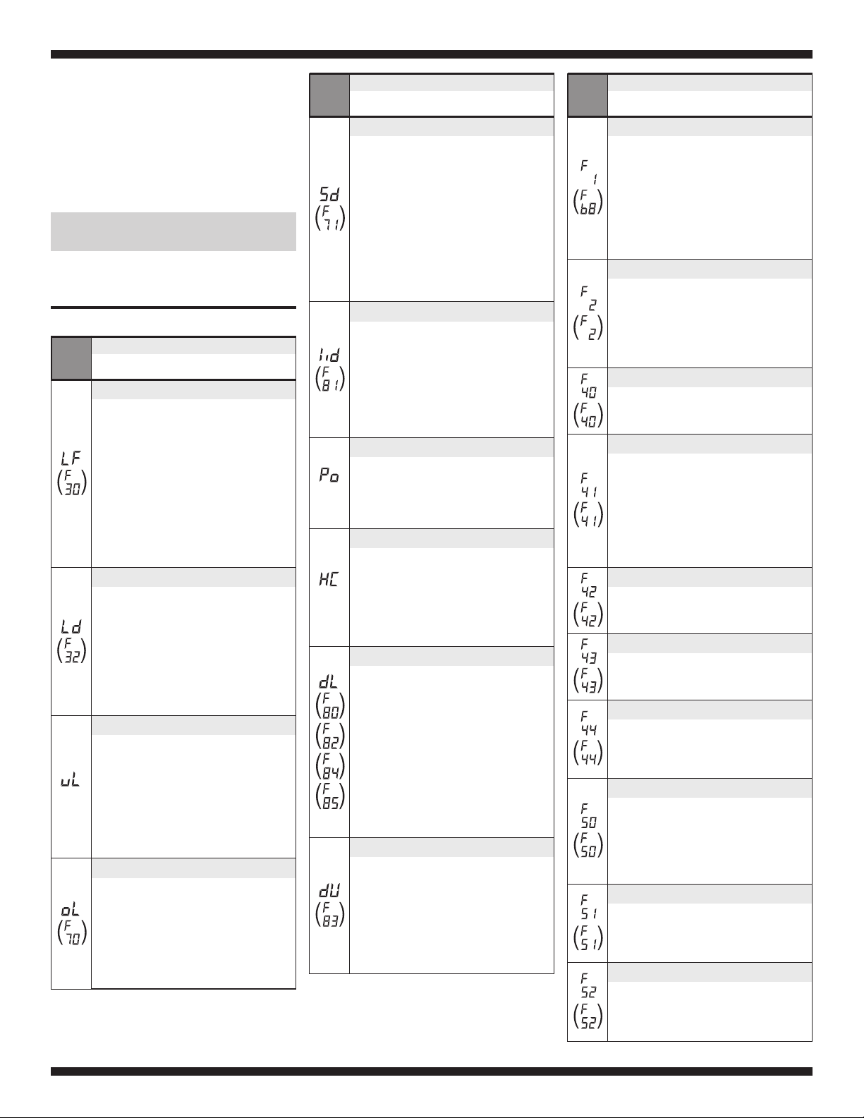
DISPLAY FAULT/ERROR CODES
Display
(Saved
Code)
EXPLANATION AND
RECOMMENDED PROCEDURE
Long Fill
LF flashes whenthewaterleveldoesnot
change foraperiodoftimeORwateris
present butcontrol does not detect thewater
levelchanging.
➔
Is water supply connectedandturnedon?
➔
Arehosescreensplugged?
➔
Is water siphoning out of the drain hose?
Check for proper drainhoseinstallation.
➔
Is thepressure hoseconnection from the tub
to the machine/motor control pinched,
kinked, plugged, or leaking air?
➔ SeeTEST#2,page4.
Long Drain
Ld flashes whenthewaterleveldoesnot
change after the drain pump is on.
➔
Is thedrain hoseorthedrain pump clogged?
➔
Is the drainhoseheight greater than 96"?
➔
Is thepressure hoseconnection from the tub
to the machine/motor control pinched,
kinked, plugged, or leaking air?
➔
Is thepumprunning? If not, see TEST #7,
page6.
(none)
Unbalanced Load
uL is displayedwhenthemachine/motor
control detectsanoff-balanceload,andis
steady on whilethewasherrunsamini-cycle
to rebalancetheload.
➔
Display clearsifmini-cyclesuccessfully
rebalancedtheload.
➔
If themini-cycleisunsuccessful,uL will
flash until the lid is opened,allowing the
customer to view and redistribute theload.
Overloaded
oL flashes when the machine/motor control
detects a load size that exceeds the
washer’s capacity OR basket cannot
disengage. This may signify:
➔
Load size exceeds washer capacity.Remove
excess laundry,thenrestart cycle.
➔
Mechanicalfriction on drive mechanism,
not allowing the basket to disengage.
Display
(Saved
Code)
EXPLANATION AND
RECOMMENDED PROCEDURE
Suds Detection
Sd is displayedwhenthemachine/motor
control, by analyzing drag on the basket,
detectsasuds-lockcondition, and is steady on
while thecontrol then runs a mini-clean out
cycle.Iftheclean outcycleisunabletocorrect
theover-sudsing problem, the cycle ends and
Sd flashes in the display. This may signify:
➔
Loadisbunchedortwistedaround agitator.
➔
Excessive detergentusage.
➔
Basket cannot engage during drain step.
➔
Mechanicalfriction on drive mechanism,
not allowing basket to engage.
Open/Close Lid
lid flasheswhen thefollowing conditions
occur:
➔
Userpresses START with lid open.
➔
UserpressesSTARTafter2consecutive
washer cycles without opening lid.
➔
The machine/motor control cannot detect the
lid switch opening and closing properly.
➔
SeeTEST#8,page6.
(none)
Pump Out(lid opened)
Po flasheswhen drain pump begins pumping
out water fromtubuponactivation by the
lid having been left open for more than 10
minutes.
➔ Close lid to stop drainpump.
(none)
Hot, Cold Reversed
HC flasheswhen the hot and cold inlethoses
arereversed.
➔ Make sureinlet hoses are connected
correctly.
➔ If hosesareinstalledproperly, Automatic
Temperature Control maybestuck in low
resistance range. SeeTest #5, page 5.
LidLockFailure
dL flashesifthefollowing conditions occur:
➔
Lidisnotclosed completely due to
interference.
➔
Check for lock interference with lid or lock
bezel.
➔
Washmedia buildup is preventing thelock
bolt from extending.
➔
Machine/motorcontrol detectsopenlid
switch whenattempting to lock.
➔
Machine/motor control cannot determine
if lidlock is in a locked state.
➔
SeeTEST#8,page6.
LidUnlockFailure
dU flashesifthefollowing conditions occur:
➔
Excessive forceonlidispreventing lock bolt
from retracting.
➔
Washmediabuildupispreventing lock bolt
from retracting.
➔
Machine/motor control cannot determine
if lid lock is in an unlocked state.
➔
SeeTEST#8,page6.
Display
(Saved
Code)
EXPLANATION AND
RECOMMENDED PROCEDURE
Pressure Signal Out-of-Range
F then 1 flasheswhen thecontrol detectsan
outofrange pressure signal.
➔
Check pressure hose connection from tub
to machine/motorcontrol.Ishosepinched,
kinked,plugged, or leaking air?
➔
If F then 1 repeats numerous times after
POWER is pressed and the pressure hose
connection is not pinched or kinked,
replace the machine/motor control.
Keypad/User Interface Failure
F then 2 flashes whenin:
➔
Diagnostic Test modeifastuck key
is detected.
➔
Standbymodeifthere is a user interface
mismatch.
➔
SeeTEST#4,page5.
ATCThermistorOpen/Short
F then 40 flasheswhen the ATC Thermistor
is detected to be open or shorted.
➔
See TEST #5, page 5.
Motor RPS Thermistor Open/Short
F then 41 flasheswhen the motor rotor
position sensor (RPS) thermistorisdetected
to be open or shorted.
➔
See TEST #3, page 4.
NOTE: This errorcodeisonly displayed when
viewing savedfault codes.
➔ See Diagnostic Test, page 1, for accessing
saved fault codes.
Heater in unknown state
F then 42 flasheswhen thecontrol cannot
detectiftheheaterisONorOFF.
➔
See TEST #9, page 6.
Heater is continuously ON
F then 43 flashes when the heater is ON
when it should be OFF.
➔
See TEST #9, page 6.
Heater cannot be turned ON
F then 44 flashes when the heater has been
turned ON by the control, but the control
cannot detect that the heater is ON.
➔
See TEST #9, page 6.
Motor Stalled
F then 50 flasheswhen the motor rotor
position sensor (RPS) sensesnorotation.
➔
Does basket turn freely? If not, make sure
bottomshipping packhasbeenremoved.
Determine cause of friction.
➔
If basket turnsfreely, seeTEST#3,page4.
Motor RPS Failure
F then 51 flasheswhen thereisamotor rotor
positionsensor (RPS)failure or lower harness
problem.
➔
See TEST #3, page 4.
Motor Stop Failure
F then 52 flasheswhen the motor rotor position
sensor (RPS) senses rotation afterStop
command.
➔
See TEST #3, page 4.
If none of the indicators light up, see TEST #1, page 4.
NECÈIP4EGAPW10240480A.ONTRAP
o
W10240480A
FOR SERVICE TECHNICIAN ONLY – D O NOT REMOVE OR DESTROY POURLETECHNICIEN SEULEMENT – NE PAS ENLEVERNIDÉTRUIRE
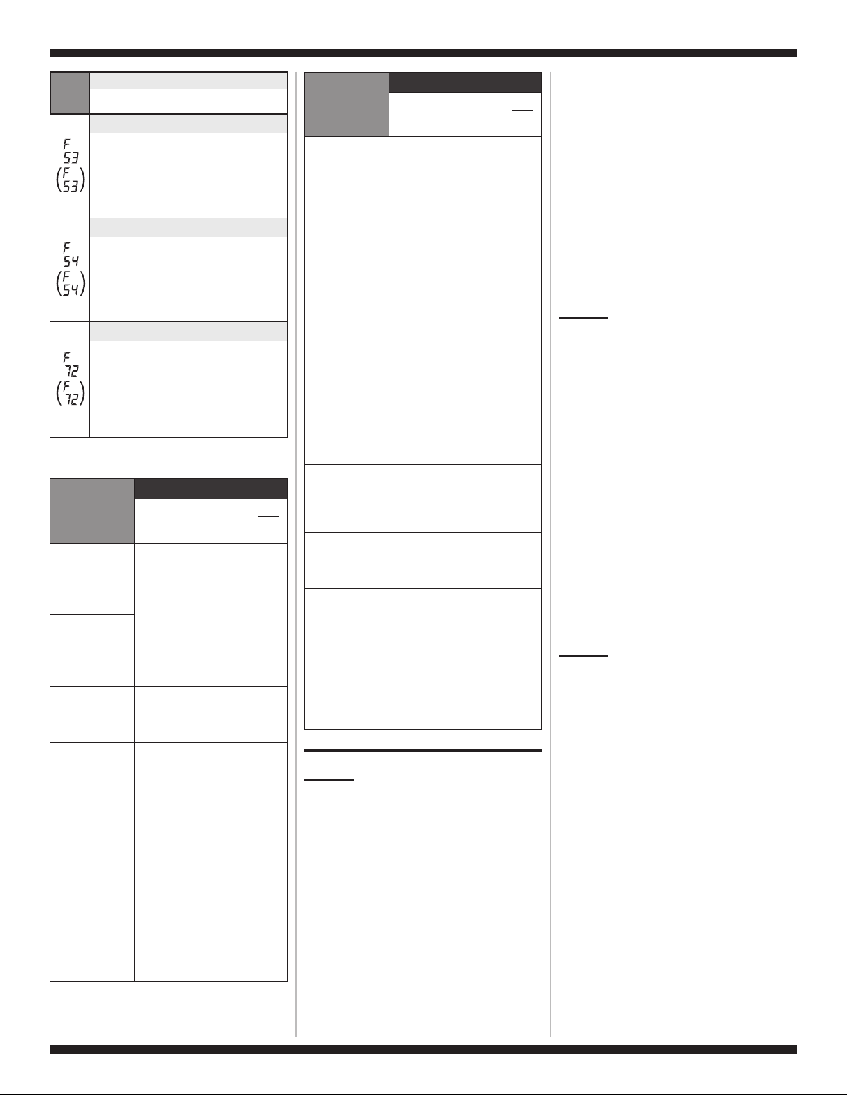
Display
(Saved
Code)
EXPLANATION AND
RECOMMENDED PROCEDURE
Motor ControlOvertemp
F then 53 flasheswhen themachine/motor
control detects high temperatureforthe motor
module.
➔
Does basket turn freely?Ifnot, determine
causeoffriction.
➔
If basket turnsfreely, seeTEST #3, at right.
MotorControl Overcurrent
F then 54 flasheswhen themachine/motor
control detects high currentforthe motor
module.
➔
Does basket turn freely?Ifnot, determine
causeoffriction.
➔
If basket turnsfreely, seeTEST #3, at right.
Basket Re-engagement Failure
F then 72 flashes when the basket check
routine fails to determine if the basket is
re-engaged after being disengaged.
➔
Is the basket floating? if yes, pump out
water. See Long Drain (Ld) procedure.
➔
Does basket turn freely? If not, determine
cause of friction.
TROUBLESHOOTING GUIDE
PROBLEM
POSSIBLE CAUSE/TEST
NOTE: Possible Cause/Test must
be performed in the sequence
shown for each problem.
WON’T POWER
UP
(No response
when buttons are
pressed.)
1. Supply connections. See
TEST #1, at right.
2. Unplug washer or disconnect
power.
3. Check harness connections.
4. User interface assembly. See
TEST #4, page 5.
WON’T START
CYCLE
(No response
when Start button
is pressed.)
WON’T SHUT
OFF WHEN
EXPECTED
1. User interface assembly. See
TEST #4, page 5.
2. Lid switch. See TEST #8,
page 6.
CONTROL
WON’T ACCEPT
SELECTIONS
User interface assembly. See
TEST #4, page 5.
WON’T
DISPENSE
1. Check water connections to
washer.
2. Check for plugged screen in
water source.
3. Log valve. See TEST #2, at
right.
WON’T FILL
1. Check water connections to
washer.
2. Check for plugged screen in
water source.
3. Log valve. See TEST #2,atright.
4. Unplug washer or disconnect
power.
5. Check harness connections.
PROBLEM
POSSIBLE CAUSE/TEST
NOTE: Possible Cause/Test must
be performed in the sequence
shown for each problem.
OVER FILLS
1. Unplug washer or disconnect
power.
2. Checkpressure hose connections.
3. Check to see if the pressure
hose has a hole, is pinched or
plugged.
4. Water level and calibration.
See TEST #6, page 5.
WON’T AGITATE
1. Make sure basket is floating.
2. Unplug washer or disconnect
power.
3. Check harness connections.
4. Lid switch. See TEST #8, page 6.
5. Motor. See TEST #3, at right.
WON’T SPIN
1. Lid switch. See TEST #8,
page 6.
2. Unplug washer or disconnect
power.
3. Check harness connections.
4. Motor. See TEST #3, at right.
WON’T DRAIN
1. Check drain hose installation.
2. Check for plugged drain hose.
3. Drain pump. See TEST #7, page6.
INCORRECT
WATER
TEMPERATURE
1. Check for swapped water
connections to washer.
2. ATC (Automatic Temperature
Control). See TEST #5,
page 5.
ALL HOT FILLS
1. ATC thermistor stuck in high
resistance range.
2. ATC (Automatic Temperature
Control). See TEST #5, page 5.
WON’T
RECIRCULATE
WATER
1. Unplug washer or disconnect
power.
2. Check for plugged recirculation
hose.
3. Check for leaks in recirculation
system.
4. Recirculation pump. See
TEST #7, page 6.
DISPLAY IS
FLASHING
See Display Fault/Error Codes,
page 3.
TROUBLESHOOTING TESTS
TEST #1 Supply connections
This test assumes that proper voltage is present at the
outlet.
1. Unplug washer or disconnect power.
2. Access the machine/motor control assembly. See
Accessing & Removing the Electronic Assemblies,
page 6.
3. With an ohmmeter, checkforcontinuity between the
neutral (N) terminal of theplugandP13-1 on the
machine/motorcontrol.Seefigures 4 and 5, page 15.
➔
If there is continuity, go to step 4.
➔
If there is no continuity, replace the power cord.
4. In a similar way, check the continuity between the L1
terminal of the plug and P13-3 on the machine/motor
control. See figures 4 and 5, page 15.
➔
If there is continuity, go to step 5.
➔
If there is no continuity, replace the power cord.
5. Visually check that the P13 connector is inserted
all the way into the machine/motor control.
6. Visually check that the user interface assembly
(P11 Connector) is properly inserted into the machine/
motor control.
7. If both visual checks pass, unplug the washer power
cord and then unplug the P11 connector (User Interface
board). Wait 1 min. 30 sec. Plug in the power cord
with only the P11 connector unplugged. Did the washer
lid lock and unlock just after plugging in? Did the
washer dispense water through any of the valves?
If not, replace the machine/motor control. If yes,
replace the user interface assembly. See Reinstalling
the Electronic Assemblies, page 6.
8. Plug in washer or reconnect power.
9. Follow procedure under Activation of Console and
Indicators Diagnostic Test mode, page 2, to verify
repair.
TEST #2 Log Valve
This test checks the electrical connections to the valves,
and the valves themselves.
1. Check the relays and electrical connections to the
valves by performing the steps under Diagnostic:
Manual, then Manual: Water Valves, page 2. Each
step in the test activates a group of valves. The
following steps assumes one (or more) valve(s)
failed to turn on.
2. For the valve(s) in question check the individual
solenoid valves:
➔
Unplug washer or disconnect power.
➔ Disconnect connector P1 and P2 from the
machine/motor control. See figure 5, page 15.
➔
Check harness connection to solenoid valves.
3. Check resistance of valve coils at contacts P1 and P2
shown in the wiring diagram on page 16. Resistance
should be between 790–840 Ω.
➔ If resistance readings are tens of ohms outside of
range, replace the entire log valve assembly.
➔ If resistance readings are within range, replace the
machine/motor control assembly.
4. Reconnect connectors P1 and P2 to the machine/
motor control.
TEST #3 Motor Circuit
This test checks the wiring to the motor and rotor
position sensor; and the motor and rotor position
sensor themselves.
NOTE: Drain water from tub.
1. See Activation of Manual Diagnostic Test Mode,
page 2 and check the motor and electrical
connections by performing the Spin test under
Manual: Motor, page 2. The following steps assumes
that this step failed.
2. Unplug washer or disconnect power.
3. Check to see if basket will turn freely.
➔
If basket turns freely, go to step 4.
➔
If basket does not turn freely, determine what is
causing the mechanical friction or lock up.
4. Remove the console to access the machine/motor
control assembly. See Accessing & Removing the
Electronic Assemblies, page 6.
5. Visually check that the P5 and P10 connectors are
inserted all the way into the machine/motor control.
➔
If visual checks pass, go to step 6.
➔
If visual checks fail, reconnect P5 and P10 and
repeat step 1.
NECÈIP5EGAPW10240480A.ONTRAP
o
W10240480A
FOR SERVICE TECHNICIAN ONLY – D O NOT REMOVE OR DESTROY POURLETECHNICIEN SEULEMENT – NE PAS ENLEVERNIDÉTRUIRE
6. Visually check that the P5 and P10 connectors are
inserted all the way into the machine/motor control.
➔
With an ohmmeter, verify resistance values as
shown below:
C
heck
b
etween
c
onnector
pins
R
esistance
values
should be:
G
o to
step7if
values are:
G
o to
s
tep12if:
P5
1-2
31 Ω ± 5 Ω
Much higher
than 31 Ω
Resistances
at all
connectors
are correct
1-3
P10
6-5
1.5 kΩ ± 100 Ω
Much higher
or much
lower than
1.5 kΩ
6-4
6-3
1-7 600 Ω to 21.2 kΩ Out of range
7. Tilt washer forward to access the bottom of the
washer and the drive motor area. See figure 1,
page 14. Remove the motor bolt, then the motor
cover to access the motor connections. See figure 2,
page 14.
8. Visually check the mounting bracket and electrical
connections to the motor and rotor position sensor
board.
➔
If visual check passes, go to step 9.
➔
If visual check fails, reconnect the electrical
connections, reassemble stator and motor cover
and repeat step 1.
9. With an ohmmeter, check for continuity between all
pins on the P10 machine motor control connector
and the motor rotor position sensor (RPS) connector.
See figures 2 and 5, pages 14 and 15.
➔
If there is continuity, check the motor windings.
If the motor windings are open, replace the drive
motor.
➔ If there is no continuity, replace the lower machine
harness.
10. With an ohmmeter, check for continuity between
all pins on the P5 machine/motor control connector
and the drive motor connector.
➔
If there is continuity, replace the drive motor.
➔
If there is no continuity, replace the lower
machine harness.
11. The drive motor and lower harness are good.
Replace the motor RPS board and perform the
Diagnostics test in step 1 to verify repair.
12. If the Diagnostics motor test in step 1 failed, then
the machine/motor control has failed:
➔
Unplug the washer or disconnect power.
➔
Replace the machine/motor control assembly.
➔
Per form the Motor Diagnostics in step 1 to verify
repair.
TEST #4 Console and Indicators
This test is performed when either of the following
situations occurs during the Console and Indicators
Diagnostic Test, page 2:
✔
No beep sound is heard
✔
Some buttons do not light indicators
None of the indicators light up:
Execute TEST #1, page 4.
No beep sound is heard:
1. Per form steps in Accessing & Removing the
Electronic Assemblies, page 6 and visually check
that the P11 connector is inserted all the way into
the machine/motor control.
➔
If visual check passes, replace the user interface
assembly.
2. Plug in washer or reconnect power.
3. Follow procedure under Activation of Console and
Indicators Diagnostic Test mode, page 2 to verify
repair.
4. If replacing the user interface assembly failed:
➔
Unplug washer or disconnect power.
➔
Replace the machine/motor control assembly.
➔
Plug in washer or reconnect power.
➔
Activate the Console and Indicators Diagnostic
Test mode, page 2 to verify repair.
Some buttons do not light indicators:
1. Per form steps in Accessing & Removing the
Electronic Assemblies, page 6 and visually check
that the console electronics and housing assembly
is properly inserted into the front console.
➔ If visual check passes, replace the user interface
assembly.
2. Plug in washer or reconnect power.
3. Follow procedure under Activation of Console and
Indicators Diagnostic Test mode, page 2 to verify
repair.
TEST #5 Automatic Temperature Control
This test checks the water inlet valves, the temperature
sensor, and the machine/motor control.
1. Check the valves by performing Test #2, page 4
before continuing to the next step.
2. Ensure proper hose connections and that
household’s hot water is present.
3. Plug in washer or reconnect power.
4. Remove all clothes from the washer.
5. Select POWER ➔ wash cycle NORMAL➔
Wash/Rinse Temp. WARM/COLD ➔ START.
6. After the tub fills and star ts to wash, stop the
washer.
7. Measure the water temperature, and verify it is
85°±10°F (29°±6°C).
➔
If the water temperature is correct,ATCis
functional.
➔
If the water temperature is incorrect, then go
to step 8.
8. Unplug washer or disconnect power.
9. Access the machine/motor control assembly. See
Accessing & Removing the Electronic Assemblies,
page 6.
10. Remove the P9 connector, and using an ohmmeter,
measure the resistance between pins P9-1 and
P9-3. Verify that the resistance is within range as
shown in the following table:
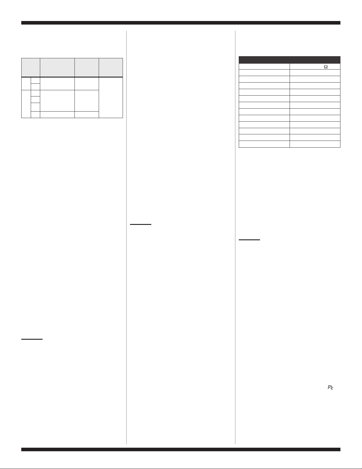
THERMISTOR RESISTANCE
Temperature Resistance(
)
32°F (0°C) 32.6–34.2 kΩ
40°F (4.4°C) 26–27.5 kΩ
50°F (10°C) 19–20.5 kΩ
60°F (16°C) 15–15.7 kΩ
70°F (21°C) 11.7–12.2 kΩ
80°F (27°C) 9.1–9.5 kΩ
90°F (32°C) 7.2–7.6 kΩ
100°F (38°C) 5.6–5.9 kΩ
110°F (44°C) 4.6–4.9 kΩ
120°F (49°C) 3.6–3.8 kΩ
130°F (55°C) 2.9–3.1 kΩ
140°F (60°C) 2.4–2.6 kΩ
➔
If the resistance is within the range shown in the
table, go to step 12.
➔
If the resistance is infinite or close to zero, go to
step 11.
11. Using an ohmmeter, measure continuity between
all pins on the P9 connector and the thermistor
contacts.
➔
If there is continuity, replace the log valve
assembly.
➔ If there is no continuity, replace the upper
harness.
12. The log valve and upper harness are good.
Replace the machine/motor control assembly. See
Reinstalling the Electronic Assemblies, page 6.
TEST #6Water Level and Pressure
Transducer Calibration
This test checks the water level sensing components,
and calibrates the pressure sensor.
1. Unplug washer or disconnect power.
2. Access the machine/motor control assembly. See
Accessing & Removing the Electronic Assemblies,
page 6.
3. Check hose connection between the pressure
transducer on the machine/motor control and the
pressure dome attached to the tub. Check to ensure
hose is routed correctly in the lower cabinet and not
pinched or crimped by the back panel.
4. Plug in washer or reconnect power.
5. Drain the tub until all water has been removed
from tub.
6. Remove all clothes from the washer.
7. Calibrate the pressure transducer:
➔
See Activation of Manual Diagnostic Test Mode,
page 2, and perform steps 1 and 2 until the
display shows
00 and the Add A Garment
indicator LED is flashing.
➔
Press and hold the Cycle Signal button until a
single beep sounds, and the display shows
to indicate zero calibration has completed.
➔
Exit Diagnostic: Manual by pressing either STOP,
PAUSE/CANCEL, or POWER.
8. Select POWER ➔ wash cycle NORMAL ➔ START.
9. Verify that the tub fills to the top of the impeller plate
(impeller models) or to a level above the agitator
vanes (agitator models), but much lower than the
SUPER Load Size or KING PLUS water level.
NOTE: On some models, the EOC button and the EOC
Off button (if present) do not have an LED indicator.
 Loading...