

Whirlpool WRS586FLDW01, WRS973CIDM00, MSB26C6MDM00, MSB26C6MDH00, MSB26C6MDE00 Installation Guide
...
INSTALLATIONINSTRUCTIONSAND OWNER'S MANUAL
Do Not Throw Away -- Additional important safety information included.
Para las instruccionos on ospa_ol, uisito nuostro s/rio do intomot.
INSTRUCTIONSD'INSTALLATIONETMANUEL D'UTILISATION
Ne pas jeter -- Autres consignes de s_curit_ importantes ci-jointes.
Table of Contents / Tabledes mati@res
REFRIGERATOR SAFETY ..................................................................... 2
Proper Disposal of Your Old Refrigerator ........................................... 3
INSTALLATION INSTRUCTIONS ......................................................... 3
Unpack the Refrigerator ...................................................................... 3
Door Removal, Leveling and Alignment ............................................. 4
Handle Installation and Removal ........................................................ 7
Location Requirements ....................................................................... 8
Electrical Requirements ...................................................................... 8
Water Supply Requirements ............................................................... 8
Connect Water Supply ........................................................................ 9
Install Air Filter ................................................................................... 11
Install Produce Preserver .................................................................. 12
Changing the Water Filter ................................................................. 13
REFRIGERATOR CARE ....................................................................... 13
Cleaning ............................................................................................ 13
Lights ................................................................................................. 14
Vacation and Moving Care ............................................................... 15
PROBLEM SOLVER ............................................................................. 16
WATER FILTER CERTIFICATIONS .................................................... 20
PERFORMANCE DATA SHEET .......................................................... 21
SI_CURITI_ DU RI_FRIGI_RATEUR ..................................................... 22
Mise au rebut appropriee de votre vieux refrigerateur ..................... 23
INSTRUCTIONS D'INSTALLATION ................................................... 23
Deballage du refrigerateur ................................................................ 23
Retrait, reglage de I'aplomb et alignement des portes .................... 24
Installation et demontage des poignees .......................................... 27
Exigences d'emplacement ............................................................... 28
Specifications electriques ................................................................. 28
Specifications de I'alimentation en eau ............................................ 29
Raccordement de la canalisation d'eau ........................................... 29
Installation du filtre & air .................................................................... 31
Installation du sachet de conservation pour produits frais .............. 32
Changer le filtre & eau ....................................................................... 33
ENTRETIEN DU RI_FRIGI_RATEUR ................................................... 34
Nettoyage .......................................................................................... 34
Lampes ............................................................................................. 34
Entretien avant les vacances ou Iors d'un demenagement ............. 36
RI_SOLUTION DE PROBLI_MES ........................................................ 37
FEUlLLE DE DONNI£'ES SUR LA PERFORMANCE .......................... 43
W10631232B
REFRIGERATORSAFETY
Your safety and the safety of others are very important.
We have provided many important safety messages in this manual and on your appliance. Always read and obey all safety
messages.
This is the safety alert symbol.
This symbol alerts you to potential hazards that can kill or hurt you and others.
All safety messages will follow the safety alert symbol and either the word "DANGER" or "WARNING."
These words mean:
You can be killed or seriously injured if you don't immediately
follow instructions.
You can be killed or seriously injured if you don't follow
instructions.
All safety messages will tell you what the potential hazard is, tell you how to reduce the chance of injury, and tell you what can
happen if the instructions are not followed.
IMPORTANT SAFETY INSTRUCTIONS
WARNING: To reduce the risk of fire, electric shock, or injury when using your refrigerator, follow these basic precautions:
[] Plug into a grounded 3 prong outlet.
[] Do not remove ground prong.
[] Do not use an adapter.
[] Do not use an extension cord.
[] Disconnect power before servicing.
[] Replace all parts and panels before operating.
[] Remove doors from your old refrigerator.
SAVE THESE INSTRUCTIONS
[] Use nonflammable cleaner.
[] Keep flammable materials and vapors, such as gasoline,
away from refrigerator.
[] Use two or more people to move and install refrigerator.
[] Disconnect power before installing ice maker (on ice maker
kit ready models only).
[] Use a sturdy glass when dispensing ice (on some models).
[] Do not hit the refrigerator glass doors (on some models).
State of California Proposition 65 Warnings:
WARNING: This product contains one or more chemicals known to the State of California to cause cancer.
WARNING: This product contains one or more chemicals known to the State of California to cause birth defects or other
reproductive harm.
2
ProperDisposalof YourOld Refrigerator
Suffocation Hazard
Remove doors from your old refrigerator.
Failure to do so can result in death or brain damage.
IMPORTANT: Child entrapment and suffocation are not problems
of the past. Junked or abandoned refrigerators are still dangerous,
even if they will sit for "just a few days." If you are getting rid of
your old refrigerator, please follow these instructions to help
prevent accidents.
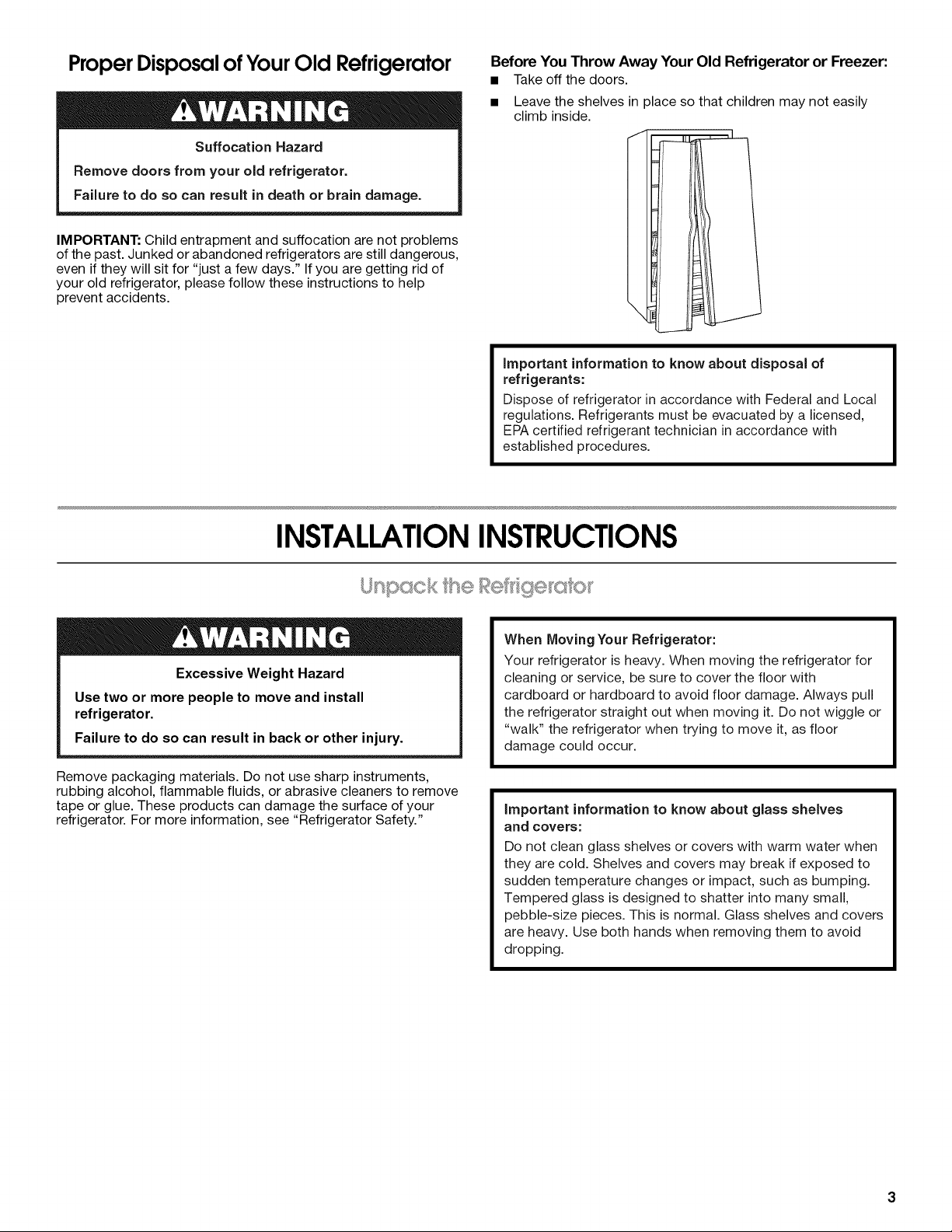
Before You Throw Away Your Old Refrigerator or Freezer:
• Takeoff the doors.
• Leave the shelves in place so that children may not easily
climb inside.
important information to know about disposal of
refrigerants:
Dispose of refrigerator in accordance with Federal and Local
regulations. Refrigerants must be evacuated by a licensed,
EPA certified refrigerant technician in accordance with
established procedures.
INSTALLATIONINSTRUCTIONS
Excessive Weight Hazard
Use two or more people to move and install
refrigerator.
Failure to do so can result in back or other injury.
Remove packaging materials. Do not use sharp instruments,
rubbing alcohol, flammable fluids, or abrasive cleaners to remove
tape or glue. These products can damage the surface of your
refrigerator. For more information, see "Refrigerator Safety."
When Moving Your Refrigerator:
Your refrigerator is heavy. When moving the refrigerator for
cleaning or service, be sure to cover the floor with
cardboard or hardboard to avoid floor damage. Always pull
the refrigerator straight out when moving it. Do not wiggle or
"walk" the refrigerator when trying to move it, as floor
damage could occur.
important information to know about glass shelves
and covers:
Do not clean glass shelves or covers with warm water when
they are cold. Shelves and covers may break if exposed to
sudden temperature changes or impact, such as bumping.
Tempered glass is designed to shatter into many small,
pebble-size pieces. This is normal. Glass shelves and covers
are heavy. Use both hands when removing them to avoid
dropping.
Gathertherequiredtoolsandpartsandreadallinstructionsbeforestartinginstallation.Savetheseinstructionsforfuturereference.
IMPORTANT:Thegraphicsonthispageareformodelswiththeicestoragebinonthedoor.Onmodelswiththeicestoragebininside
thefreezer,thewiringandwaterdispensertubingconfigurationsaresimplerthanwhatisshowninthesegraphics.Pleasereadall
instructionsonthenextfewpagesformoreinformation.
NOTE:Beforemovingyourproductintoyourhome,measurethedoorwayofyourhometoseewhetheryouneedtoremovethe
refrigeratorandfreezerdoors.Ifdoorremovalisnecessary,seetheinstructionsbelow.
IMPORTANT:Beforeyoubegin,turntherefrigeratorcontrolOFForturncoolingoff.Unplugrefrigeratorordisconnectpower.Remove
food,theicestoragebin(onsomemodels),andanyadjustabledoororutilitybinsfromdoors.
__ Electrical Shock Hazard
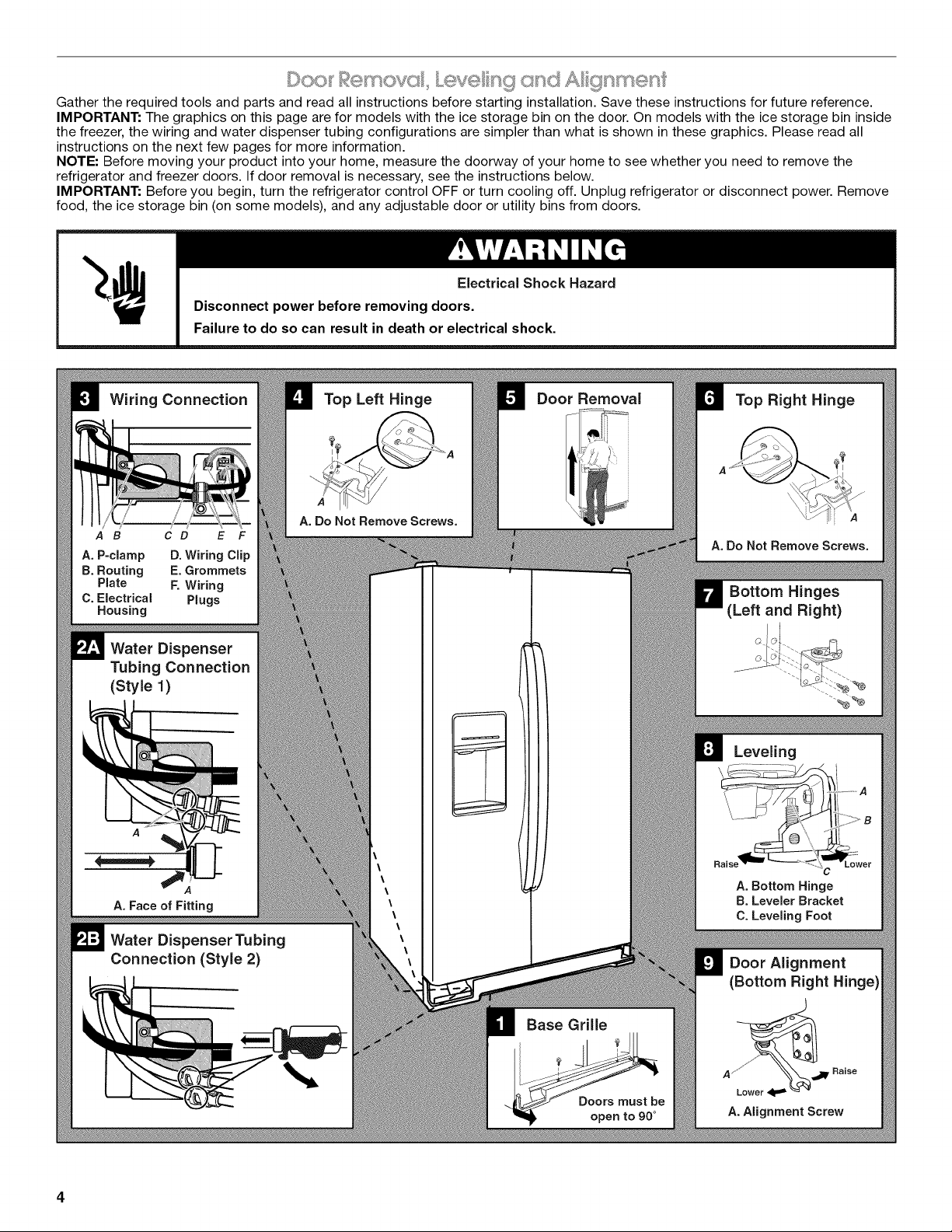
Wiring Connection
A B C D E F
A, P-clamp D. Wiring Clip
B. Routing E. Grommets
Plate F. Wiring
C. Electrical Plugs
Housing
Disconnect power before removing doors.
Failure to do so can result in death or electrical shock.
Top Left Hinge
A. Do Not Remove Screws.
Door Removal
Water Dispenser
Tubing Connection
(Style 1)
Top Right Hinge
A. Do Not Remove Screws.
Bottom Hinges
(Left and Right)
Leveling
A
,4
A, Face of Fitting
Water Dispenser Tubing
Connection (Style 2)
Base Grille
A, Bottom Hinge
B. Leveler Bracket
C. Leveling Foot
Door Alignment
(Bottom Right Hinge)
A
_Lower 4 =_ _ "
A.Alignment Screw
Raise

TOOLSNEEDED:
Bubblelevel,Phillipsscrewdriver,3/le"hexkey,1/4"hex-head
socketwrench,1/4"and%e"open-endedwrenchesoradjustable
wrench,internalstardriveor3/8"hex-headsocketwrench
Remove the Doors
Electrical Shock Hazard
Disconnect power before removing doors.
Failure to do so can result in death or electrical shock.
1=
Unplug refrigerator or disconnect power.
2.
Open both doors to 90°. Remove the base grille by removing
the two screws, then pulling out on the outside corners. See
Graphic 1.
NOTE: The doors must only be opened to 90°. If they are
opened all the way, the base grille will not come off.
3=
Disconnect the water tubing, located behind the base grille on
the freezer door side. The dispenser tubing runs through the
door hinge, and must be disconnected in order to remove the
door.
NOTE: On models with the ice storage bin on the door, there
are two water tubing connections, as shown. On models with
the ice storage bin inside the freezer, there is only one water
tubing connection.
• Style 1: Press the colored outer ring against the face of
fitting and pull the water tubing free. See Graphic 2A.
NOTE: Keep the water tubing connector attached to the
tube that runs underneath the freezer. The door cannot be
removed if the connector is still attached to the tube that
runs through the door hinge.
Style 2: Firmly pull on the clasp to release the tube, then
pull the water tubing free. See Graphic 2B.
NOTE: Keep the clasp attached to the tube that runs
underneath the freezer.
4=
Disconnect the wiring, located behind the base grille on the
freezer door side. See Graphic 3.
On models with the ice storage bin on the door:
NOTE: There are two wiring bundles that run underneath the
freezer - a large bundle with a large grommet and two white
plugs at the end, and a small bundle with a small grommet
and one yellow plug at the end.
• Remove the P-clamp using a 1/4"hex-head socket wrench.
Remove the small wiring bundle from the P-clamp.
• Remove the wiring clip using a 1/4"hex-head socket
wrench.
• Pull the electrical housing out from under the refrigerator.
Disconnect the wiring plugs from the housing.
• Gently pull the large wiring bundle (with two white plugs)
through the routing plate.
On models with the ice storage bin inside the freezer:
NOTE: The wiring configuration is simpler than what is shown
in Graphic 3. There is only one wiring bundle with one wiring
plug, and there is not a routing plate.
• Remove the wiring clip using a 1/4"hex-head socket
wrench.
• Pull the electrical housing out from under the refrigerator.
Disconnect the wiring plug from the housing.
5=
Close both doors and keep them closed until you are ready to
lift them free from the cabinet.
6.
Use a 3/le"hex key to remove the top left hinge screws as
shown. See Graphic 4.
IMPORTANT: Do not remove either screw A.
Excessive Weight Hazard
Use two or more people to lift the freezer door.
Failure to do so can result in back or other injury.
7=
Lift freezer door straight up off bottom hinge. See Graphic 5.
The water tubing and wiring remain attached to the freezer
door and pull through the bottom left hinge.
NOTE: This may require two people - one to lift the door and
another to feed the water tubing and wiring through the hinge.
On models with the ice storage bin on the door:
Be sure the hole in the hinge is clear of obstructions, then
gently pull one water tube through the hinge. (Avoid
kinking the tube.) Next, gently pull the other water tube
through the hinge, again avoiding kinks. Finally, gently pull
the wiring bundle (including the grommet and wiring plugs)
through the hinge.
On
models with the ice storage bin inside the freezer:
Be sure the hole in the hinge is clear of obstructions, then
gently pull the water tube through the hinge. (Avoid kinking
the tube.) Next, gently pull the wiring bundle (including the
grommet and wiring plug) through the hinge.
IMPORTANT: Rest the door on its side on a soft, clean
surface, such as a towel, blanket or piece of cardboard. This
will help avoid damaging the door, water tubing and wiring.
8=
Use a 3/le"hex key to remove the top right hinge screws as
shown. See Graphic 6.
IMPORTANT: Do not remove either screw A.
g=
Lift the refrigerator door straight up off bottom hinge.
IMPORTANT: Rest the door on its side on a soft, clean
surface, such as a towel, blanket or piece of cardboard. This
will help avoid damaging the door.
10.
It may not be necessary to remove the bottom hinges to move
the refrigerator through a doorway. Both bottom hinges have
similar construction.
• If necessary, use an internal star drive or a 3/8"hex-head
socket wrench to remove the bottom hinges. See
Graphic 7.
IMPORTANT: The leveler brackets are mounted behind
the hinges. If you remove the hinges, make sure that the
leveler brackets are replaced when reinstalling the hinges.
Replace the Doors and Hinges
1. Replace both bottom hinges, if removed. Make sure that the
leveler brackets are assembled behind the hinges. Tighten
screws.
IMPORTANT: When the screws are tightened properly, there
should not be any gaps between the refrigerator, leveler
bracket and hinge.
ExcessiveWeightHazard
Usetwoor more people to lift the freezer door.
Failure to do so can result in back or other injury.
2.
Before replacing the freezer door on the bottom left hinge,
feed the wiring and water tubing through the hinge.
On models with the ice storage bin on the door:
• Feed the small wiring bundle through the hinge.
Assistance may be needed.
IMPORTANT: Do not feed the large wiring bundle through
the hinge. This bundle is intended to run directly from the
door to the connections beneath the freezer. Forcing the
large bundle through the hinge may damage the door
and/or the wiring, and will keep the door from closing
properly.
Feed both water tubes through the bottom left hinge, then
replace the freezer door on the hinge. Assistance may be
needed.
On models with the ice storage bin inside the freezer:
• Feed the wiring bundle through the hinge. Assistance may
be needed.
• Feed the water tube through the bottom left hinge, then
replace the freezer door on the hinge. Assistance may be
needed.
NOTE: Provide additional support for the doors while the top
hinges are being replaced. Do not depend on the door magnets to
hold the doors in place while you are working.
3. Align and replace the top left hinge as shown. See Graphic 4.
Tighten screws.
4. Reconnect water tubing and wiring.
IMPORTANT: Do not intertwine the water tubing and wiring
bundles when reconnecting them.
On models with the ice storage bin on the door:
Water Connection Style 1: Push the larger %e"(7.94 mm)
water tube into the blue fitting until it stops, then push the
smaller 1/4"(6.35 ram) water tube into the green fitting until
it stops. See Graphic 2A.
Water Connection Style 2: Push the black water tube
with the blue tip into the blue fitting until it stops. Close
the clasp around the tubing, making sure it snaps into
place. Repeat this process to connect the red-tipped
black water tube and the red fitting. See Graphic 2B.
Reinstall the P-clamp around the small wiring bundle (with
one yellow plug), then replace the P-clamp on the top
screw hole of the routing plate. See Graphic 3.
Gently route the large wiring bundle (with two white plugs)
through the hole in the routing plate, so that the wiring
runs behind the right side of the routing plate. See
Graphic 3.
NOTE: The large wiring bundle should always remain
below the small wiring bundle.
Reconnect the wiring plugs to the electrical housing, then
push the housing back under the refrigerator. Align the left
hole in the front lip of the housing with the right hole in the
refrigerator's base crossbar. See Graphic 3.
Reinstall the wiring clip over the grommets. First install the
smaller grommet into the top of the clip, then install the
larger grommet into the bottom of the clip (closest to the
screw hole). See Graphic 3.
Align the clip's screw hole with the left hole in the electrical
housing and the right hole in the crossbar, and screw in
the clip using a single screw. Tighten screw. See
Graphic 3.
IMPORTANT: Once connected, the wiring bundles should
not be taut. Some flexibility is needed to allow the freezer
door to open properly.
On
models with the ice storage bin inside the freezer:
• Water Connection Style 1: Push the water tube into the
fitting until it stops. See Graphic 2A.
Water Connection Style 2: Push the water tube into the
fitting until it stops. Close the clasp around the tubing,
making sure it snaps into place. See Graphic 2B.
Reconnect the wiring plug to the electrical housing, then
push the housing back under the refrigerator. Align the left
hole in the front lip of the housing with the right hole in the
refrigerator's base crossbar. See Graphic 3.
• Reinstall the wiring clip over the grommet. See Graphic 3.
Align the clip's screw hole with the left hole in the electrical
housing and the right hole in the crossbar, and screw in
the clip using a single screw. Tighten screw. See
Graphic 3.
IMPORTANT: Once connected, the wiring should not be
taut. Some flexibility is needed to allow the freezer door to
open properly.
5. Replace the refrigerator door by lifting the door onto the
bottom right hinge.
6. Align and replace the top right hinge as shown. See Graphic 6.
Tighten screws.
7. Replace the ice storage bin (on some models) and any
adjustable door or utility bins.
Electrical Shock Hazard
Plug into a grounded 3 prong outlet.
Do not remove ground prong.
Do not use an adapter.
Do not use an extension cord.
Failure to follow these instructions can result in death,
fire, or electrical shock.
8. Plug refrigerator into agrounded3 prong outlet.
Leveling and Door Closing
Your refrigerator has two adjustable front feet -- one on the right
and one on the left. In most cases, the refrigerator should be
steady when both feet are touching the floor. Ifyour refrigerator
seems unsteady or if you want the doors to close more easily,
adjust the refrigerator's tilt using the instructions below:
1. Move the refrigerator into its final location. If necessary, open
both doors to 90° and remove the base grille. See Graphic 1.
2. The two leveling feet are located on the brackets on each side
of the product. See Graphic 8.
NOTE: Having someone push against the top of the refrigerator
takes some weight off the leveling feet. This makes it easier to
make adjustments.
6
3.
Use a 1/4"open-ended or adjustable wrench to adjust the
leveling feet. Turn the leveling foot to the left to raise that side
of the product, or turn it to the right to lower that side of the
product.
NOTE: Both leveling feet should be snug against the floor, and
the rollers should not touch the floor. This keeps the
refrigerator from rolling forward when opening the doors.
4=
Open both doors again and check that they close as easily as
you like. If not, tilt the refrigerator slightly more to the rear by
turning the leveling feet to the left. It may take several more
turns, and you should turn both leveling feet the same
amount.
5. Use a bubble level to check the leveling of the refrigerator.
NOTE: Whenever you need to move the refrigerator, turn the
leveling feet to the right until they are no longer touching the
ground. This will allow the refrigerator to roll more easily.
Door Alignment
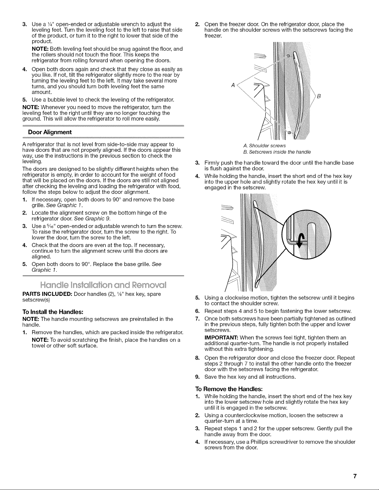
2.
Open the freezer door. On the refrigerator door, place the
handle on the shoulder screws with the setscrews facing the
freezer.
A
A refrigerator that is not level from side-to-side may appear to
have doors that are not properly aligned. If the doors appear this
way, use the instructions in the previous section to check the
leveling.
The doors are designed to be slightly different heights when the
refrigerator is empty, in order to account for the weight of food
that will be placed on the doors. If the doors are still not aligned
after checking the leveling and loading the refrigerator with food,
follow the steps below to adjust the door alignment.
1. If necessary, open both doors to 90 ° and remove the base
grille. See Graphic 1.
2. Locate the alignment screw on the bottom hinge of the
refrigerator door. See Graphic 9.
3. Use a s/16"open-ended or adjustable wrench to turn the screw.
To raise the refrigerator door, turn the screw to the right. To
lower the door, turn the screw to the left.
4. Check that the doors are even at the top. If necessary,
continue to turn the alignment screw until the doors are
aligned.
5. Open both doors to 90°. Replace the base grille. See
Graphic 1.
PARTS INCLUDED: Door handles (2), 1/s"hex key, spare
setscrew(s)
To Install the Handles:
NOTE: The handle mounting setscrews are preinstalled in the
handle.
1. Remove the handles, which are packed inside the refrigerator.
NOTE: To avoid scratching the finish, place the handles on a
towel or other soft surface.
A. Shoulder screws
B. Setscrews inside the handle
3. Firmly push the handle toward the door until the handle base
is flush against the door.
4. While holding the handle, insert the short end of the hex key
into the upper hole and slightly rotate the hex key until it is
engaged in the setscrew.
5.
Using a clockwise motion, tighten the setscrew until it begins
to contact the shoulder screw.
6.
Repeat steps 4 and 5 to begin fastening the lower setscrew.
7.
Once both setscrews have been partially tightened as outlined
in the previous steps, fully tighten both the upper and lower
setscrews.
IMPORTANT: When the screws feel tight, tighten them an
additional quarter-turn. The handle is not properly installed
without this extra tightening.
8.
Open the refrigerator door and close the freezer door. Repeat
steps 2 through 7 to install the other handle onto the freezer
door with the setscrews facing the refrigerator.
9.
Save the hex key and all instructions.
To
Remove the Handles:
1.
While holding the handle, insert the short end of the hex key
into the lower setscrew hole and slightly rotate the hex key
until it is engaged in the setscrew.
2.
Using a counterclockwise motion, loosen the setscrew a
quarter-turn at a time.
3.
Repeat steps 1 and 2 for the upper setscrew. Gently pull the
handle away from the door.
4.
If necessary, use a Phillips screwdriver to remove the shoulder
screws from the door.
!!equ emen, ts
Explosion Hazard
Keep flammable materials and vapors, such as
gasoline, away from refrigerator.
Failure to do so can result in death, explosion, or fire.
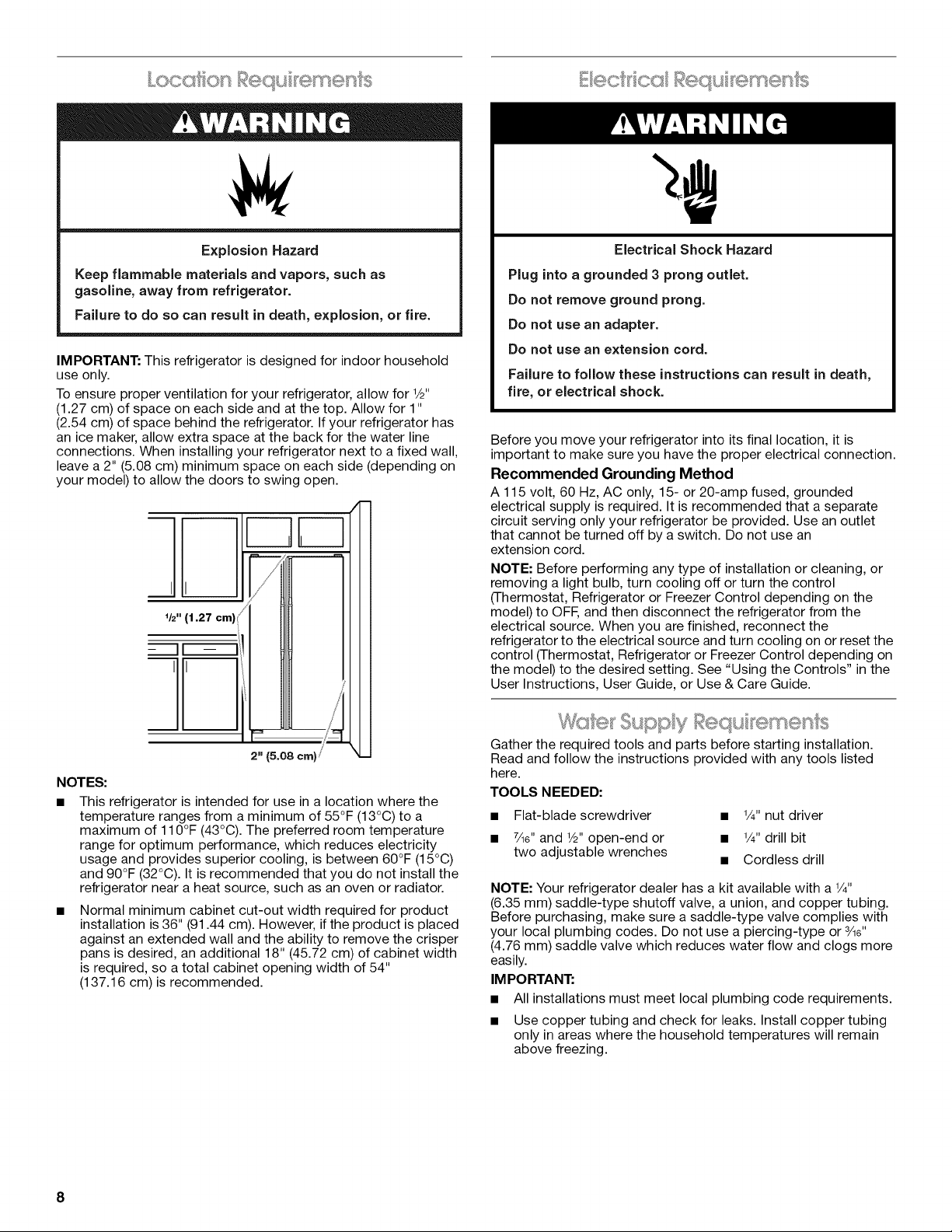
IMPORTANT: This refrigerator is designed for indoor household
use only.
To ensure proper ventilation for your refrigerator, allow for V2"
(1.27 cm) of space on each side and at the top. Allow for 1"
(2.54 cm) of space behind the refrigerator. If your refrigerator has
an ice maker, allow extra space at the back for the water line
connections. When installing your refrigerator next to a fixed wall,
leave a 2" (5.08 cm) minimum space on each side (depending on
your model) to allow the doors to swing open.
I
V2" (1.27
Electrical Shock Hazard
Plug into a grounded 3 prong outlet.
Do not remove ground prong.
Do not use an adapter.
Do not use an extension cord.
Failure to follow these instructions can result in death,
fire, or electrical shock.
Before you move your refrigerator into its final location, it is
important to make sure you have the proper electrical connection.
Recommended Grounding Method
A 115 volt, 60 Hz, AC only, 15- or 20-amp fused, grounded
electrical supply is required. It is recommended that a separate
circuit serving only your refrigerator be provided. Use an outlet
that cannot be turned off by a switch. Do not use an
extension cord.
NOTE: Before performing any type of installation or cleaning, or
removing a light bulb, turn cooling off or turn the control
(Thermostat, Refrigerator or Freezer Control depending on the
model) to OFF,and then disconnect the refrigerator from the
electrical source. When you are finished, reconnect the
refrigerator to the electrical source and turn cooling on or reset the
control (Thermostat, Refrigerator or Freezer Control depending on
the model) to the desired setting. See "Using the Controls" in the
User Instructions, User Guide, or Use & Care Guide.
/
2" (5.08 cm)
NOTES:
This refrigerator is intended for use in a location where the
temperature ranges from a minimum of 55°F (13°C) to a
maximum of 110°F (43°C). The preferred room temperature
range for optimum performance, which reduces electricity
usage and provides superior cooling, is between 60°F (15°C)
and 90°F (32°C). It is recommended that you do not install the
refrigerator near a heat source, such as an oven or radiator.
Normal minimum cabinet cut-out width required for product
installation is 36" (91.44 cm). However, if the product is placed
against an extended wall and the ability to remove the crisper
pans is desired, an additional 18" (45.72 cm) of cabinet width
is required, so a total cabinet opening width of 54"
(137.16 cm)is recommended.
Gather the required tools and parts before starting installation.
Read and follow the instructions provided with any tools listed
here.
TOOLS NEEDED:
• Flat-blade screwdriver • V4" nut driver
• 7Ae"and V_"open-end or • %" drill bit
two adjustable wrenches • Cordless drill
NOTE: Your refrigerator dealer has a kit available with a V4"
(6.35 mm) saddle-type shutoff valve, a union, and copper tubing.
Before purchasing, make sure a saddle-type valve complies with
your local plumbing codes. Do not use a piercing-type or 3Ae"
(4.76 mm) saddle valve which reduces water flow and clogs more
easily.
IMPORTANT:
• All installations must meet local plumbing code requirements.
• Use copper tubing and check for leaks. Install copper tubing
only in areas where the household temperatures will remain
above freezing.
8
Water Pressure
Connect to Water Line
A cold water supply with water pressure of between 30 and
120 psi (207 and 827 kPa) is required to operate the water
dispenser and ice maker. Ifyou have questions about your water
pressure, call a licensed, qualified plumber.
• If your refrigerator has a water dispenser: After installation is
complete, use the water dispenser to check the water
pressure.
With the water filter removed, dispense 1 cup (237 mL) of
water. If 1 cup of water is dispensed in 8 seconds or less,
the water pressure to the refrigerator meets the minimum
requirement.
• If it takes longer than 8 seconds to dispense 1 cup of
water, the water pressure to the refrigerator is lower than
recommended. See "Problem Solver" for suggestions.
Reverse Osmosis Water Supply
IMPORTANT: The pressure of the water supply coming out of a
reverse osmosis system going to the water inlet valve of the
refrigerator needs to be between 30 and 120 psi (207 and
827 kPa).
If a reverse osmosis water filtration system is connected to your
cold water supply, the water pressure to the reverse osmosis
system needs to be a minimum of 40 to 60 psi (276 to 414 kPa).
If the water pressure to the reverse osmosis system is less than
40 to 60 psi (276 to 414 kPa):
• Check to see whether the sediment filter in the reverse
osmosis system is blocked. Replace the filter if necessary.
Allow the storage tank on the reverse osmosis system to refill
after heavy usage.
If your refrigerator has a water filter, it may further reduce the
water pressure when used in conjunction with a reverse
osmosis system. Remove the water filter. See "Water Filtration
System" in the User Instructions, User Guide, or Use & Care
Guide.
If you have questions about your water pressure, call a licensed,
qualified plumber.
++,J,OF/" @0 f_,: @_'
Read all directions before you begin.
IM PORTANT:
• Plumbing shall be installed in accordance with the
International Plumbing Code and any local codes and
ordinances.
The gray water tubing on the back of the refrigerator (which is
used to connect to the household water line) is a PEX
(cross-linked polyethylene) tube. Copper and PEX tubing
connections from the household water line to the refrigerator
are acceptable, and will help avoid oft-taste or odor in your ice
or water. Check for leaks.
If PEX tubing is used instead of copper, we recommend the
following Whirlpool Part Numbers:
W10505928RP (7 ft [2.14 m] jacketed PEX),
8212547RP (5 ft [1.52 m] PEX), or
W10267701RP (25 ft [7.62 m] PEX).
• Install tubing only in areas where temperatures will remain
above freezing.
TOOLS NEEDED:
Gather the required tools and parts before starting installation.
• Flat-blade screwdriver
• 7/le"and 1/2"open-end wrenches or two adjustable wrenches
• 1/4"nut driver
IMPORTANT: If you turn the refrigerator on before the water line is
connected, turn the ice maker OFE
Style 1 (Recommended)
1. Unplug refrigerator or disconnect power.
2. Turn OFF main water supply. Turn ON nearest faucet long
enough to clear line of water.
3. Use a quarter-turn shutoff valve or the equivalent, served by a
1/2"copper household supply line.
NOTE: To allow sufficient water flow to the refrigerator, a
minimum 1/2"size copper household supply line is
recommended.
I/ l
A
B
C
A. Bulb
B. Nut
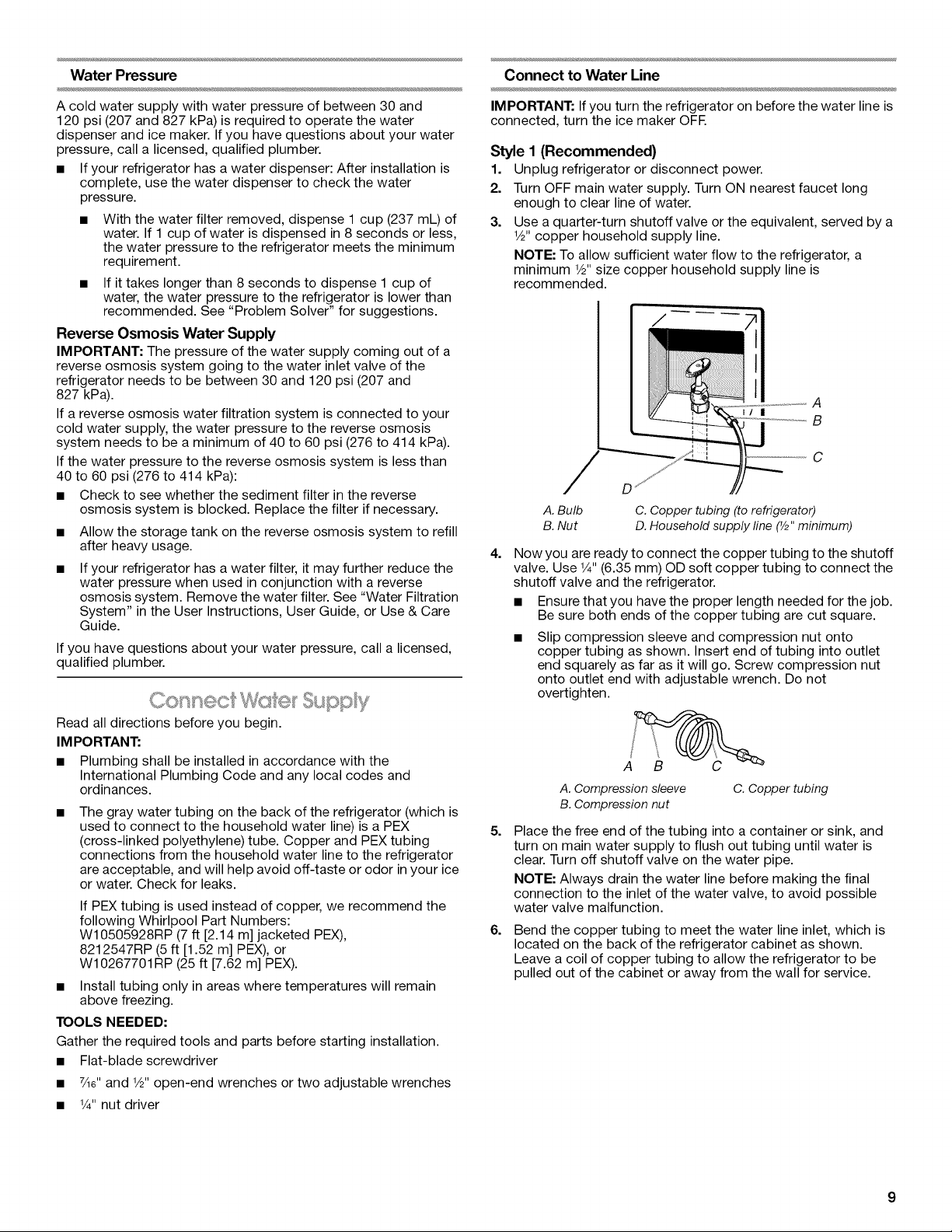
4.
Now you are ready to connect the copper tubing to the shutoff
C. Copper tubing (to refrigerator)
D. Household supply fine (Y2"minimum)
valve. Use 1/4"(6.35 mm) OD soft copper tubing to connect the
shutoff valve and the refrigerator.
• Ensure that you have the proper length needed for the job.
Be sure both ends of the copper tubing are cut square.
Slip compression sleeve and compression nut onto
copper tubing as shown. Insert end of tubing into outlet
end squarely as far as it will go. Screw compression nut
onto outlet end with adjustable wrench. Do not
overtighten.
A. Compression sleeve
B. Compression nut
5.
Place the free end of the tubing into a container or sink, and
C. Copper tubing
turn on main water supply to flush out tubing until water is
clear. Turn off shutoff valve on the water pipe.
NOTE: Always drain the water line before making the final
connection to the inlet of the water valve, to avoid possible
water valve malfunction.
6.
Bend the copper tubing to meet the water line inlet, which is
located on the back of the refrigerator cabinet as shown.
Leave a coil of copper tubing to allow the refrigerator to be
pulled out of the cabinet or away from the wall for service.
Style 2
1. Unplug refrigerator or disconnect power.
2. Turn OFF main water supply. Turn ON nearest faucet long
enough to clear line of water.
3. Locate a 1/2"(1.27 cm) to 11/4"(3.18 cm) vertical cold water
pipe near the refrigerator.
IMPORTANT:
• Make sure it is a cold water pipe.
• Horizontal pipe will work, but drill on the top side of the
pipe, not the bottom. This will help keep water away from
the drill and normal sediment from collecting in the valve.
4. Determine the length of copper tubing you need. Measure
from the connection on the lower rear corner of refrigerator to
the water pipe. Add 7 ft (2.1 m) to allow for cleaning. Use 1/4"
(6.35 mm) O.D. (outside diameter) copper tubing. Be sure both
ends of copper tubing are cut square.
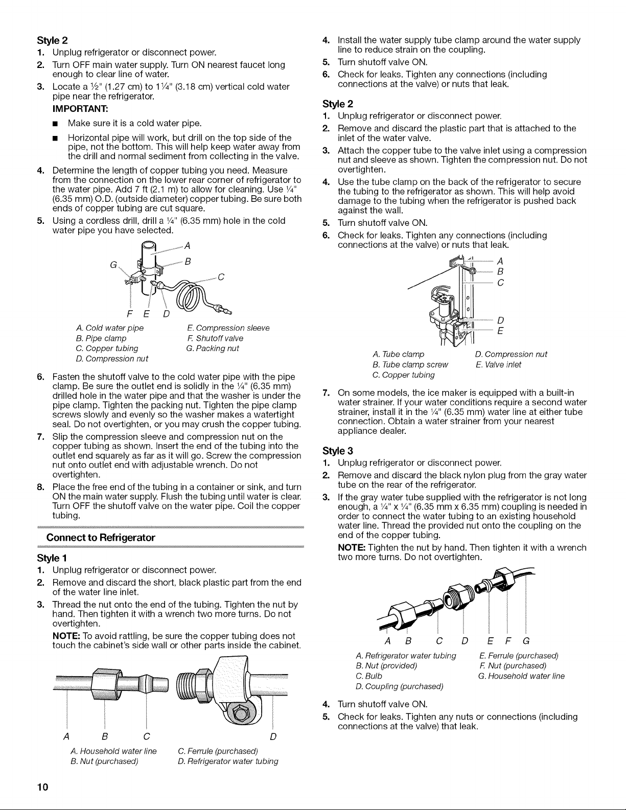
5. Using a cordless drill, drill a 1/4"(6.35 mm) hole inthe cold
water pipe you have selected.
4=
Install the water supply tube clamp around the water supply
line to reduce strain on the coupling.
5.
Turn shutoff valve ON.
6.
Check for leaks. Tighten any connections (including
connections at the valve) or nuts that leak.
Style 2
1. Unplug refrigerator or disconnect power.
2. Remove and discard the plastic part that is attached to the
inlet of the water valve.
3.
Attach the copper tube to the valve inlet using a compression
nut and sleeve as shown. Tighten the compression nut. Do not
overtighten.
4=
Use the tube clamp on the back of the refrigerator to secure
the tubing to the refrigerator as shown. This will help avoid
damage to the tubing when the refrigerator is pushed back
against the wall.
5.
Turn shutoff valve ON.
6.
Check for leaks. Tighten any connections (including
connections at the valve) or nuts that leak.
_.....................B
A. Cold water pipe
B. Pipe clamp
C. Copper tubing
D. Compression nut
E. Compression sleeve
E Shutoff valve
G. Packing nut
6. Fasten the shutoff valve to the cold water pipe with the pipe
clamp. Be sure the outlet end is solidly in the 1/4"(6.35 mm)
drilled hole in the water pipe and that the washer is under the
pipe clamp. Tighten the packing nut. Tighten the pipe clamp
screws slowly and evenly so the washer makes a watertight
seal. Do not overtighten, or you may crush the copper tubing.
7. Slip the compression sleeve and compression nut on the
copper tubing as shown. Insert the end of the tubing into the
outlet end squarely as far as it will go. Screw the compression
nut onto outlet end with adjustable wrench. Do not
overtighten.
8. Place the free end of the tubing in a container or sink, and turn
ON the main water supply. Flush the tubing until water is clear.
Turn OFF the shutoff valve on the water pipe. Coil the copper
tubing.
Connect to Refrigerator
Style 1
1. Unplug refrigerator or disconnect power.
2. Remove and discard the short, black plastic part from the end
of the water line inlet.
3.
Thread the nut onto the end of the tubing. Tighten the nut by
hand. Then tighten it with a wrench two more turns. Do not
overtighten.
NOTE: To avoid rattling, be sure the copper tubing does not
touch the cabinet's side wall or other parts inside the cabinet.
A B C
A. Household water line
B. Nut (purchased)
C. Ferrule (purchased)
D. Refrigerator water tubing
D
__ A
.........................D
..... E
A. Tubeclamp D.Compression nut
B. Tubeclamp screw E.Valveinlet
C.Copper tubing
7=
On some models, the ice maker is equipped with a built-in
water strainer. If your water conditions require a second water
strainer, install it in the 1/4"(6.35 mm) water line at either tube
connection. Obtain a water strainer from your nearest
appliance dealer.
Style 3
1. Unplug refrigerator or disconnect power.
2. Remove and discard the black nylon plug from the gray water
tube on the rear of the refrigerator.
3. If the gray water tube supplied with the refrigerator is not long
enough, a V4"x 1/4"(6.35 mm x 6.35 mm) coupling is needed in
order to connect the water tubing to an existing household
water line. Thread the provided nut onto the coupling on the
end of the copper tubing.
NOTE: Tighten the nut by hand. Then tighten it with a wrench
two more turns. Do not overtighten.
A B C
A. Refrigerator water tubing
B. Nut (provided)
C. Bulb
D. Coupling (purchased)
D E F G
E. Ferrule (purchased)
E Nut (purchased)
G. Household water line
4. Turn shutoff valve ON.
5. Check for leaks. Tighten any nuts or connections (including
connections at the valve) that leak.
10
Complete the Installation
Electrical Shock Hazard
Plug into a grounded 3 prong outlet.
Do not remove ground prong.
Do not use an adapter.
Do not use an extension cord.
Failure to follow these instructions can result in death,
fire, or electrical shock.
1. Plug into a grounded 3 prong outlet.
2. Flush the water system. See "Water and Ice Dispensers" in the
User Instructions or User Guide.
NOTE: Allow 24 hours to produce the first batch of ice. Allow
72 hours to completely fill ice container.
(o_} some modes}
On some models, your refrigerator's accessory packet includes
an air filter, which must be installed prior to use. On some models,
the air filter is already installed at the factory.
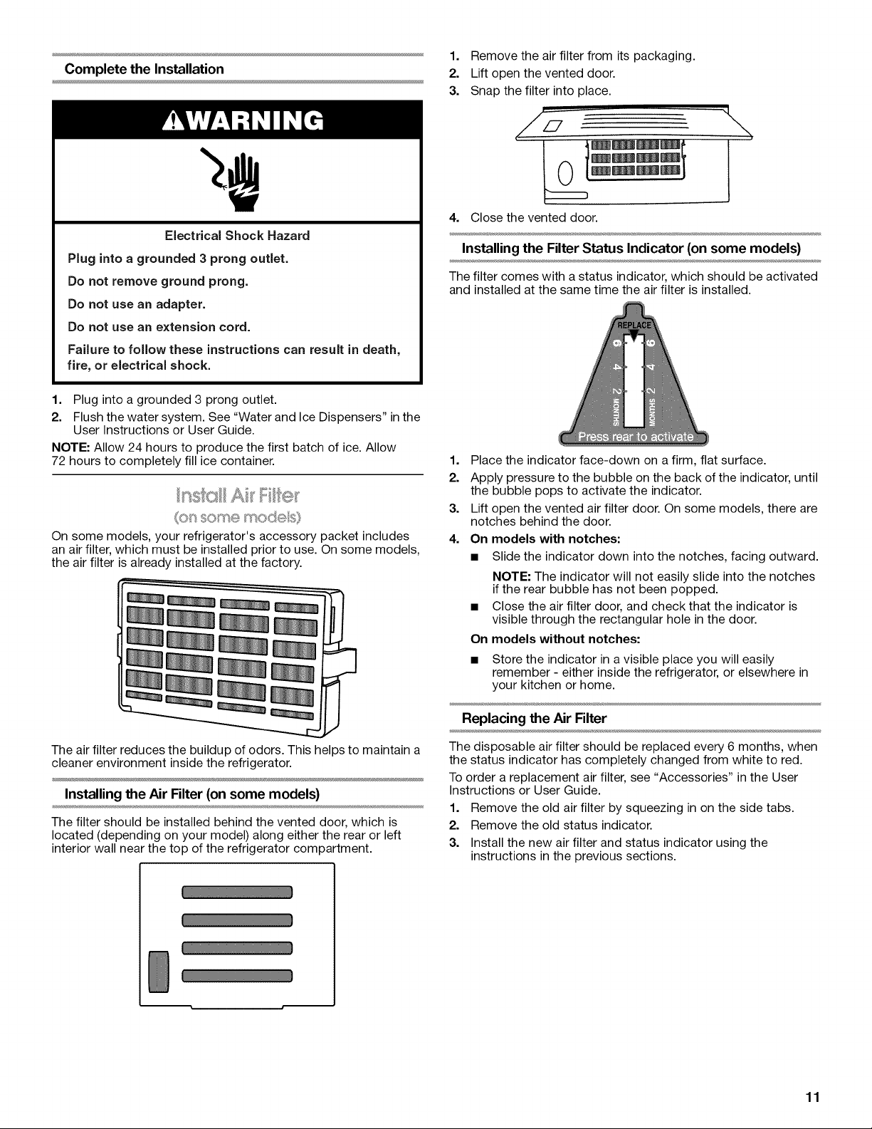
1. Remove the air filter from its packaging.
2. Lift open the vented door.
3. Snap the filter into place.
\
4. Close the vented door.
Installing the Filter Status Indicator (on some models)
The filter comes with a status indicator, which should be activated
and installed at the same time the air filter is installed.
1. Place the indicator face-down on a firm, flat surface.
2. Apply pressure to the bubble on the back of the indicator, until
the bubble pops to activate the indicator.
3. Lift open the vented air filter door. On some models, there are
notches behind the door.
4. On models with notches:
• Slide the indicator down into the notches, facing outward.
NOTE: The indicator will not easily slide into the notches
if the rear bubble has not been popped.
Close the air filter door, and check that the indicator is
visible through the rectangular hole in the door.
On models without notches:
• Store the indicator in a visible place you will easily
remember - either inside the refrigerator, or elsewhere in
your kitchen or home.
The air filter reduces the buildup of odors. This helps to maintain a
cleaner environment inside the refrigerator.
Installing the Air Filter (on some models)
The filter should be installed behind the vented door, which is
located (depending on your model) along either the rear or left
interior wall near the top of the refrigerator compartment.
Replacing the Air Filter
The disposable air filter should be replaced every 6 months, when
the status indicator has completely changed from white to red.
To order a replacement air filter, see "Accessories" in the User
Instructions or User Guide.
1. Remove the old air filter by squeezing in on the side tabs.
2. Remove the old status indicator.
3. Install the new air filter and status indicator using the
instructions in the previous sections.
11
(o_"_some modes}
On some models, your refrigeratoCs accessory packet includes a
Produce Preserver, which should be installed prior to use. On
some models, the Produce Preserver is already installed at the
factory.
The Produce Preserver absorbs ethylene, allowing the ripening
process of many produce items to slow down. As a result, certain
produce items will stay fresh longer.
Ethylene production and sensitivity varies depending on the type
of fruit or vegetable. To preserve freshness, it is best to separate
produce with sensitivity to ethylene from fruits that produce
moderate to high amounts of ethylene.
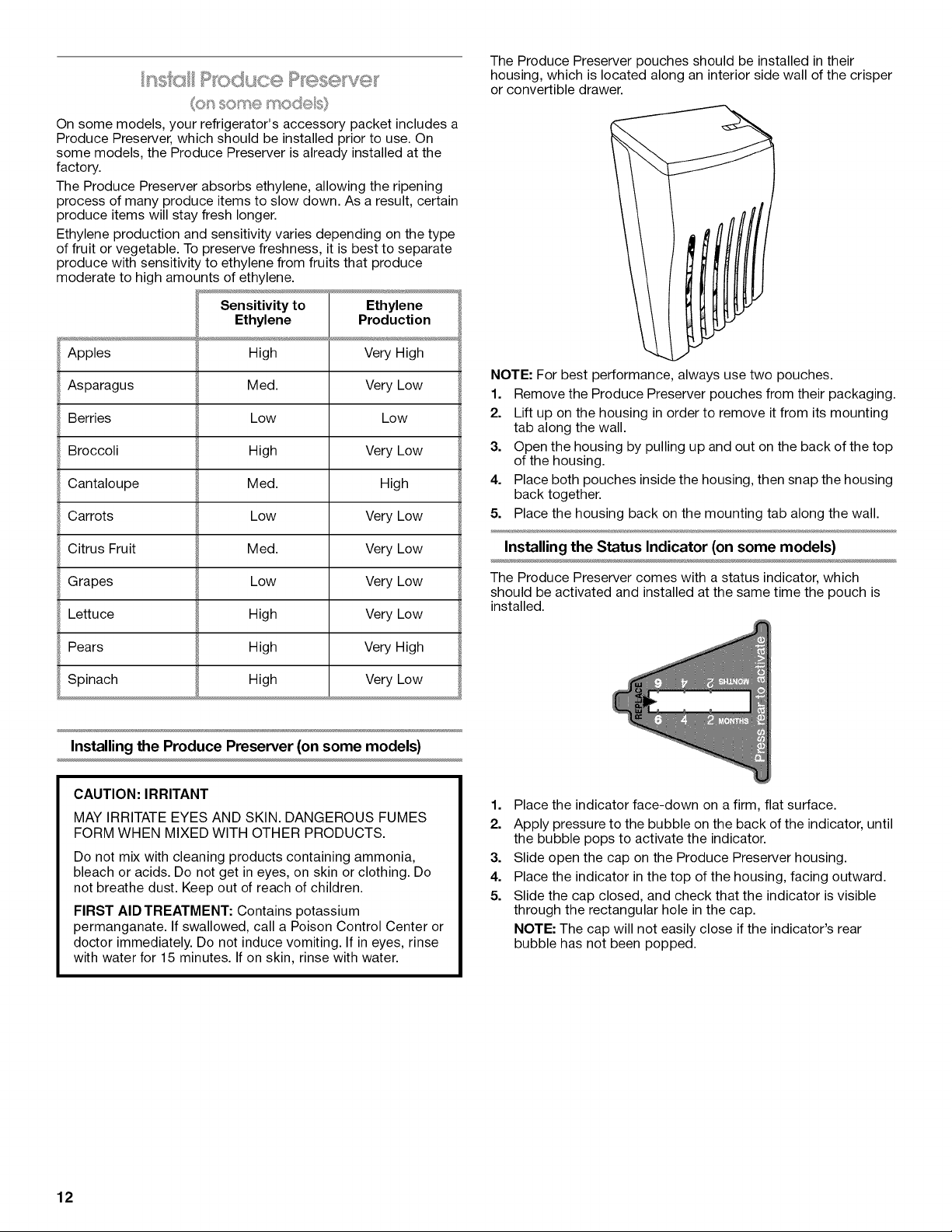
The Produce Preserver pouches should be installed in their
housing, which is located along an interior side wall of the crisper
or convertible drawer.
Sensitivity to
Ethylene
Apples
Asparagus
Berries
Broccoli
Cantaloupe
Carrots Low Very Low
Citrus Fruit Med. Very Low
Grapes Low Very Low
Lettuce High Very Low
Pears High Very High
Spinach High Very Low
Installing the Produce Preserver (on some models)
High
Med.
Low
High
Med.
Ethylene
Production
Very High
Very Low
Low
Very Low
High
NOTE: For best performance, always use two pouches.
1. Remove the Produce Preserver pouches from their packaging.
2. Lift up on the housing in order to remove it from its mounting
tab along the wall.
3. Open the housing by pulling up and out on the back of the top
of the housing.
4. Place both pouches inside the housing, then snap the housing
back together.
5. Place the housing back on the mounting tab along the wall.
Installing the Status Indicator (on some models)
The Produce Preserver comes with a status indicator, which
should be activated and installed at the same time the pouch is
installed.
CAUTION: IRRITANT
MAY IRRITATE EYES AND SKIN. DANGEROUS FUMES
FORM WHEN MIXED WITH OTHER PRODUCTS.
Do not mix with cleaning products containing ammonia,
bleach or acids. Do not get in eyes, on skin or clothing. Do
not breathe dust. Keep out of reach of children.
FIRST AID TREATMENT: Contains potassium
permanganate. If swallowed, call a Poison Control Center or
doctor immediately. Do not induce vomiting. If in eyes, rinse
with water for 15 minutes. If on skin, rinse with water.
12
1. Place the indicator face-down on a firm, flat surface.
2. Apply pressure to the bubble on the back of the indicator, until
the bubble pops to activate the indicator.
3. Slide open the cap on the Produce Preserver housing.
4. Place the indicator in the top of the housing, facing outward.
5. Slide the cap closed, and check that the indicator is visible
through the rectangular hole in the cap.
NOTE: The cap will not easily close if the indicator's rear
bubble has not been popped.
Replacing the Produce Preserver (on some models)
The disposable pouches should be replaced every 6 months,
when the status indicator has completely changed from white to
red.
To order replacements, see "Accessories" in the User Instructions
or User Guide.
1. Remove the old pouches from the Produce Preserver housing.
2. Remove the old status indicator.
3. Install the new pouches and status indicator using the
instructions in the previous sections.
Do not use with water that is microbiologically unsafe or
of unknown quality without adequate disinfection before
or after the system. Systems certified for cyst reduction
may be used on disinfected waters that may contain
filterable cysts.
The water filter status light will help you know when to change
your water filter. See "Water Filtration System" in the User
Instructions or User Guide.
NOTE: If water flow to your water dispenser or ice maker
decreases noticeably, change the filter sooner. The filter should be
replaced at least every 6 months, depending on your water quality
and usage.
1. Locate the water filter in the top-right corner of the refrigerator
compartment.
2. Lift open the filter cover door. The filter will be released and
then be ejected as the door is opened.
3. When the door is completely open, pull the filter straight out.
NOTE: There may be some water in the filter. Some spilling
may occur. Use a towel to wipe up any spills.
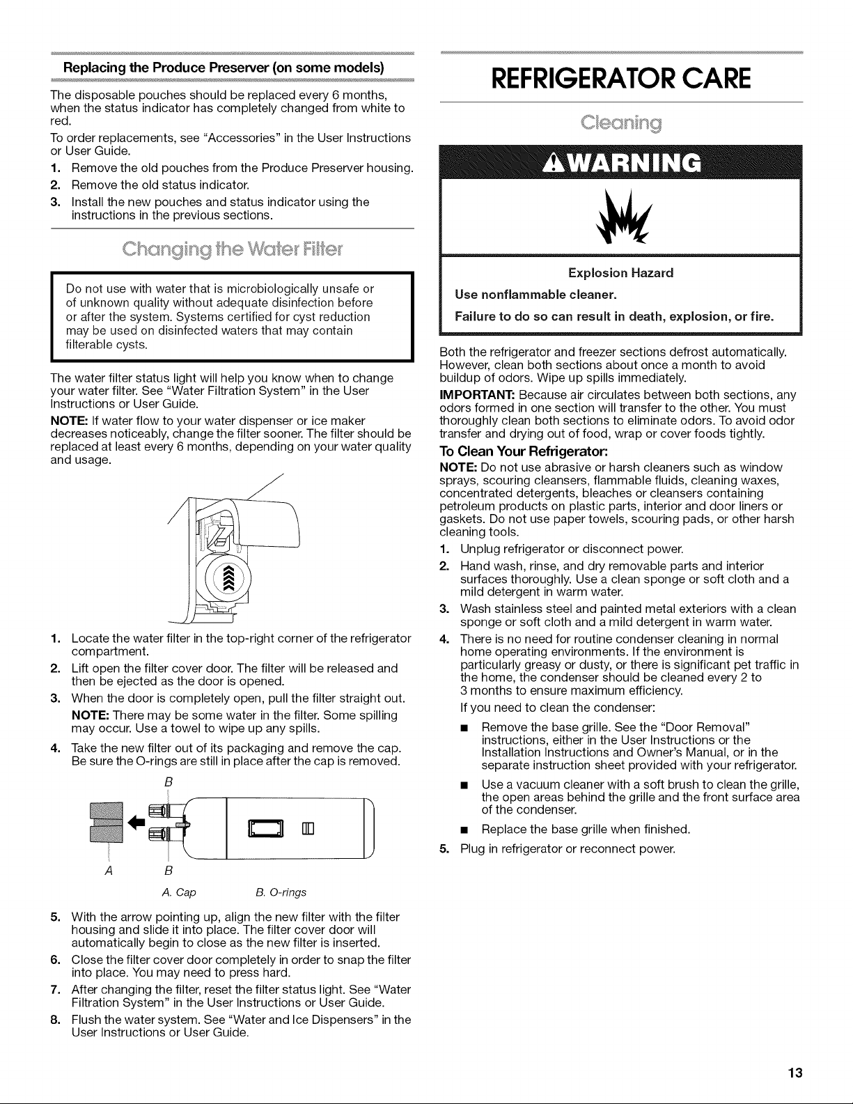
4.
Take the new filter out of its packaging and remove the cap.
Be sure the O-rings are still in place after the cap is removed.
B
[]
B
A. Cap B. O-rings
REFRIGERATORCARE
Explosion Hazard
Use nonflammable cleaner.
Failure to do so can result in death, explosion, or fire.
Both the refrigerator and freezer sections defrost automatically.
However, clean both sections about once a month to avoid
buildup of odors. Wipe up spills immediately.
IMPORTANT: Because air circulates between both sections, any
odors formed in one section will transfer to the other. You must
thoroughly clean both sections to eliminate odors. To avoid odor
transfer and drying out of food, wrap or cover foods tightly.
To Clean Your Refrigerator:
NOTE: Do not use abrasive or harsh cleaners such as window
sprays, scouring cleansers, flammable fluids, cleaning waxes,
concentrated detergents, bleaches or cleansers containing
petroleum products on plastic parts, interior and door liners or
gaskets. Do not use paper towels, scouring pads, or other harsh
cleaning tools.
1. Unplug refrigerator or disconnect power.
2. Hand wash, rinse, and dry removable parts and interior
surfaces thoroughly. Use a clean sponge or soft cloth and a
mild detergent in warm water.
3. Wash stainless steel and painted metal exteriors with a clean
sponge or soft cloth and a mild detergent in warm water.
4. There is no need for routine condenser cleaning in normal
home operating environments. If the environment is
particularly greasy or dusty, or there is significant pet traffic in
the home, the condenser should be cleaned every 2 to
3 months to ensure maximum efficiency.
If you need to clean the condenser:
Remove the base grille. See the "Door Removal"
instructions, either in the User Instructions or the
Installation Instructions and Owner's Manual, or in the
separate instruction sheet provided with your refrigerator.
• Use a vacuum cleaner with a soft brush to clean the grille,
the open areas behind the grille and the front surface area
of the condenser.
• Replace the base grille when finished.
5. Plug in refrigerator or reconnect power.
5. With the arrow pointing up, align the new filter with the filter
housing and slide it into place. The filter cover door will
automatically begin to close as the new filter is inserted.
6. Close the filter cover door completely in order to snap the filter
into place. You may need to press hard.
7. After changing the filter, reset the filter status light. See "Water
Filtration System" in the User Instructions or User Guide.
8. Flush the water system. See "Water and Ice Dispensers" in the
User Instructions or User Guide.
13
IMPORTANT: The light bulbs in both the refrigerator and freezer
compartments of your new refrigerator may use LED technology.
If the lights do not illuminate when the refrigerator and/or freezer
door is opened, call for assistance or service. In the U.S.A., call
1-800-253-1301. In Canada, call 1-800-807-6777.
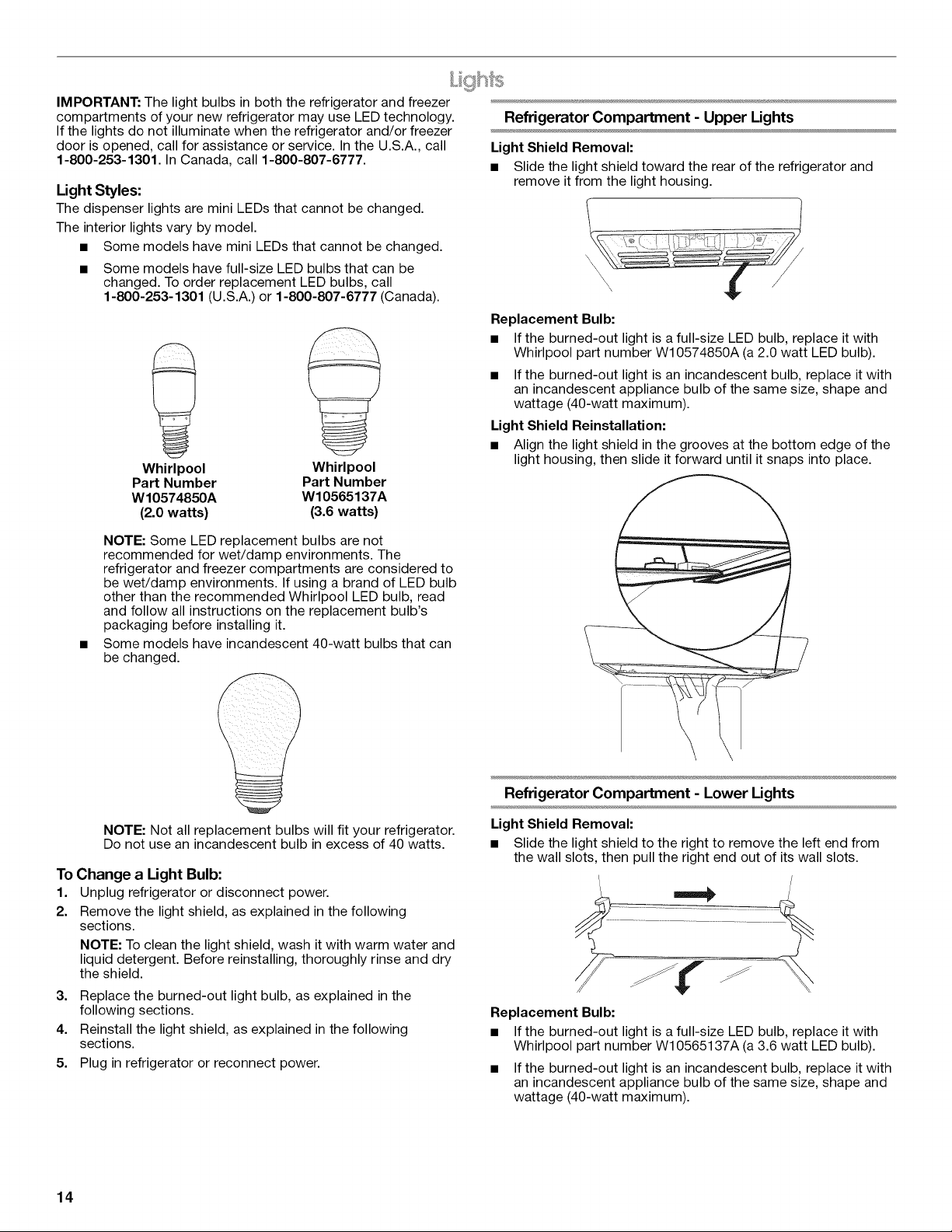
Light Styles:
The dispenser lights are mini LEDs that cannot be changed.
The interior lights vary by model.
• Some models have mini LEDs that cannot be changed.
• Some models have full-size LED bulbs that can be
changed. To order replacement LED bulbs, call
1-800-253-1301 (U.S.A.) or 1-800-807-6777 (Canada).
Whirlpool
Part Number
W10574850A
(2.0 watts)
Whirlpool
Part Number
W10565137A
(3.6 watts)
NOTE: Some LED replacement bulbs are not
recommended for wet/damp environments. The
refrigerator and freezer compartments are considered to
be wet/damp environments. If using a brand of LED bulb
other than the recommended Whirlpool LED bulb, read
and follow all instructions on the replacement bulb's
packaging before installing it.
Some models have incandescent 40-watt bulbs that can
be changed.
Refrigerator Compartment - Upper Lights
Light Shield Removal:
• Slide the light shield toward the rear of the refrigerator and
remove it from the light housing.
Replacement Bulb:
• If the burned-out light is a full-size LED bulb, replace it with
Whirlpool part number W10574850A (a 2.0 watt LED bulb).
• If the burned-out light is an incandescent bulb, replace it with
an incandescent appliance bulb of the same size, shape and
wattage (40-watt maximum).
Light Shield Reinstallation:
• Align the light shield in the grooves at the bottom edge of the
light housing, then slide it forward until it snaps into place.
NOTE: Not all replacement bulbs will fit your refrigerator.
Do not use an incandescent bulb in excess of 40 watts.
To Change a Light Bulb:
1. Unplug refrigerator or disconnect power.
2. Remove the light shield, as explained in the following
sections.
NOTE: To clean the light shield, wash it with warm water and
liquid detergent. Before reinstalling, thoroughly rinse and dry
the shield.
3.
Replace the burned-out light bulb, as explained in the
following sections.
4.
Reinstall the light shield, as explained in the following
sections.
5.
Plug in refrigerator or reconnect power.
14
Refrigerator Compartment - Lower Lights
Light Shield Removal:
• Slide the light shield to the right to remove the left end from
the wall slots, then pull the right end out of its wall slots.
Replacement Bulb:
• If the burned-out light is a full-size LED bulb, replace it with
Whirlpool part number W10565137A (a 3.6 watt LED bulb).
• If the burned-out light is an incandescent bulb, replace it with
an incandescent appliance bulb of the same size, shape and
wattage (40-watt maximum).
 Loading...