

Whirlpool WRIT41W, WRIT41N Service Manual
Rev..00 Whirlpool Of India Ltd.
NOV -10
Service Manual
Top Mount
No Frost Refrigerator
1

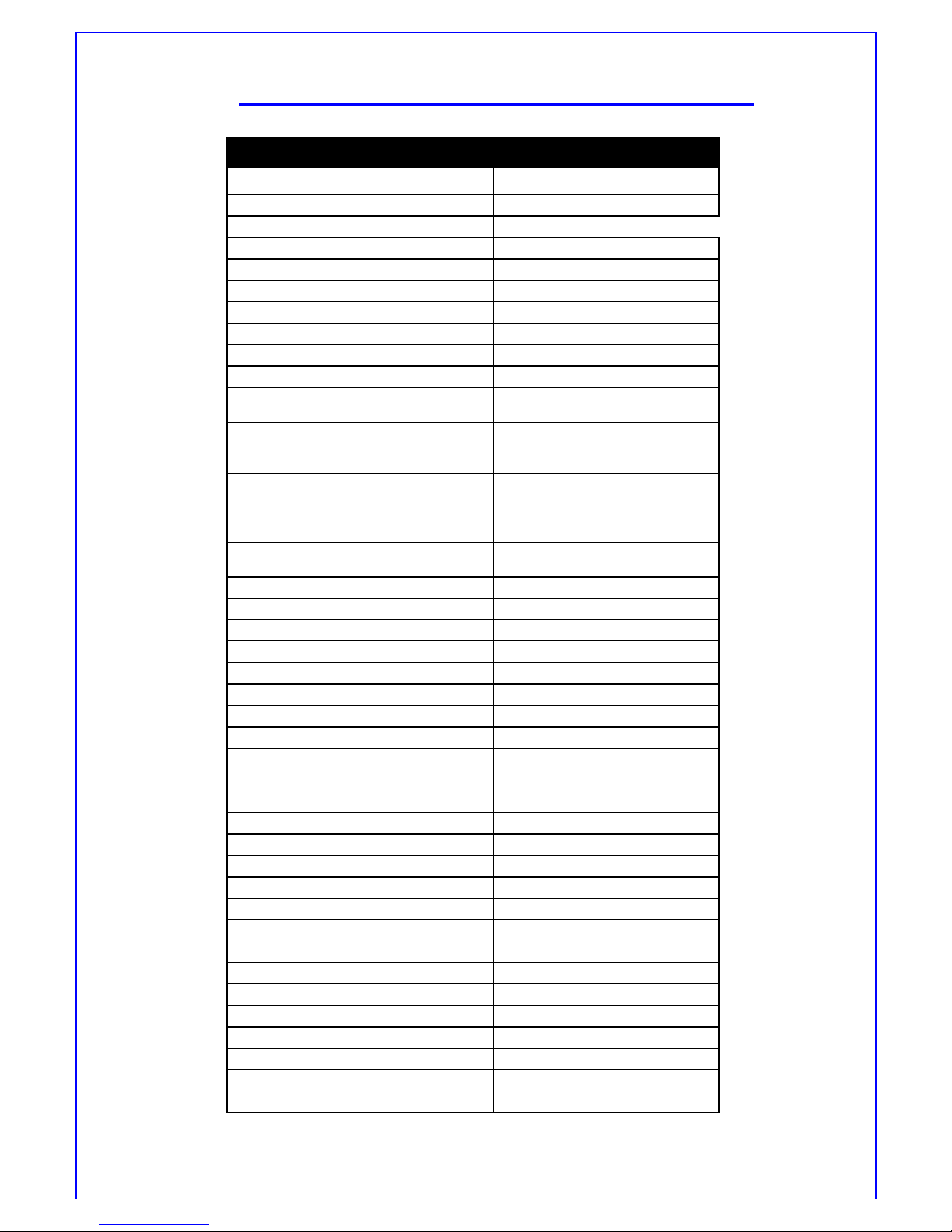
INDEX
Sno. Detail Page No.
1.0 Model Range 3
2.0 Safety Precuations 4
3.0 Feature /Technical specification 6
4.0 Controls & Electronic configuration 7
5.0 Wiring Diagram 9
6.0 Assembly/Dissembly 11
7.0 Controlling the refrigerator temperature 14
8.0 Error indications & Trigger 15
9.0 Exploded Views 17
10.0 Part List 23
2

NO FROST REFRIGERATOR: MODEL RANGE
410L Dlx - WRIT41W
410L Dlx – WRIT41N
3
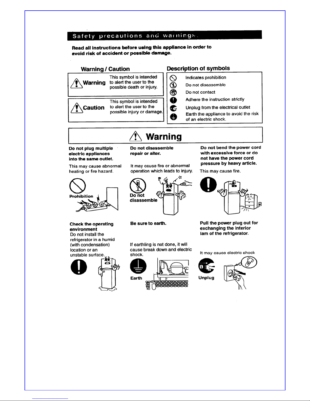
4
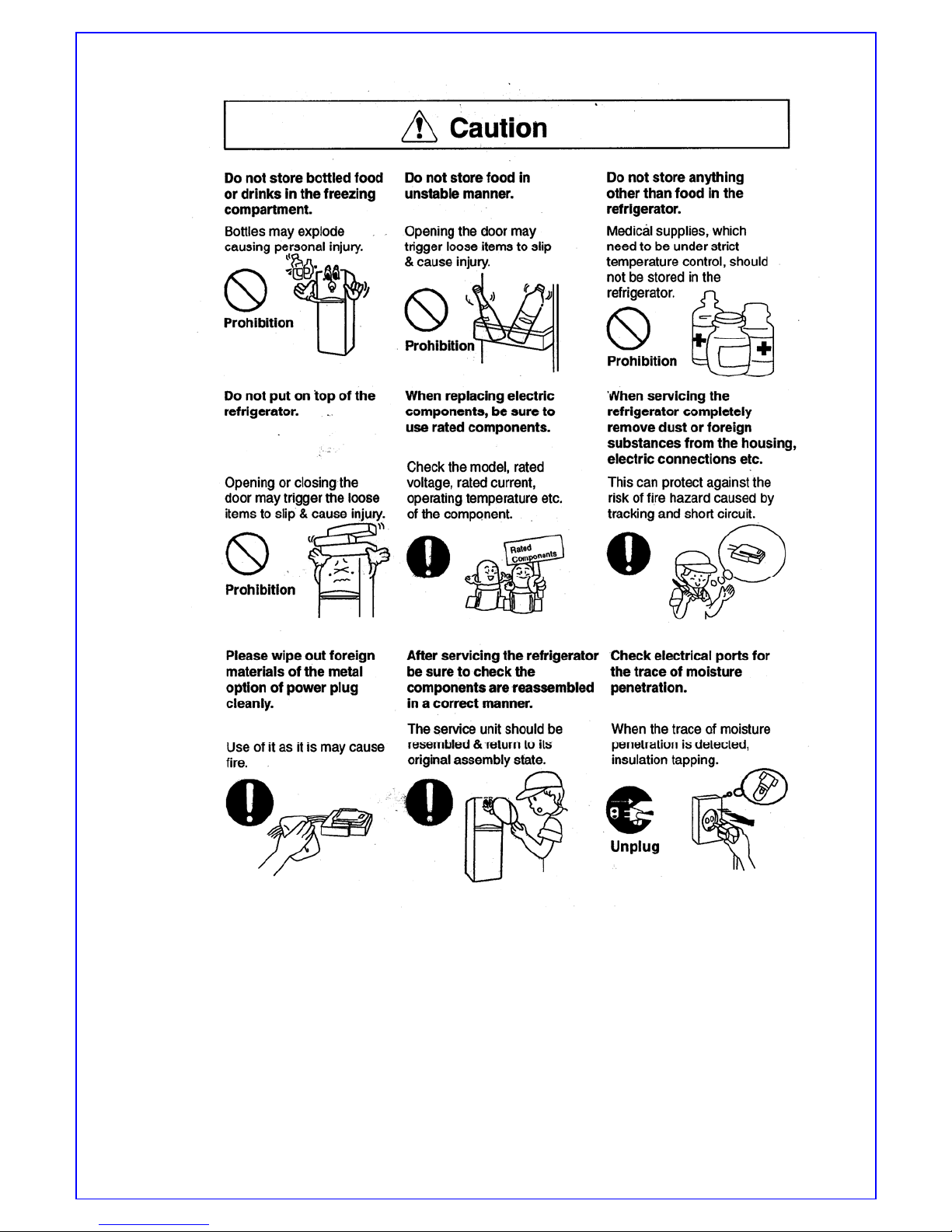
5
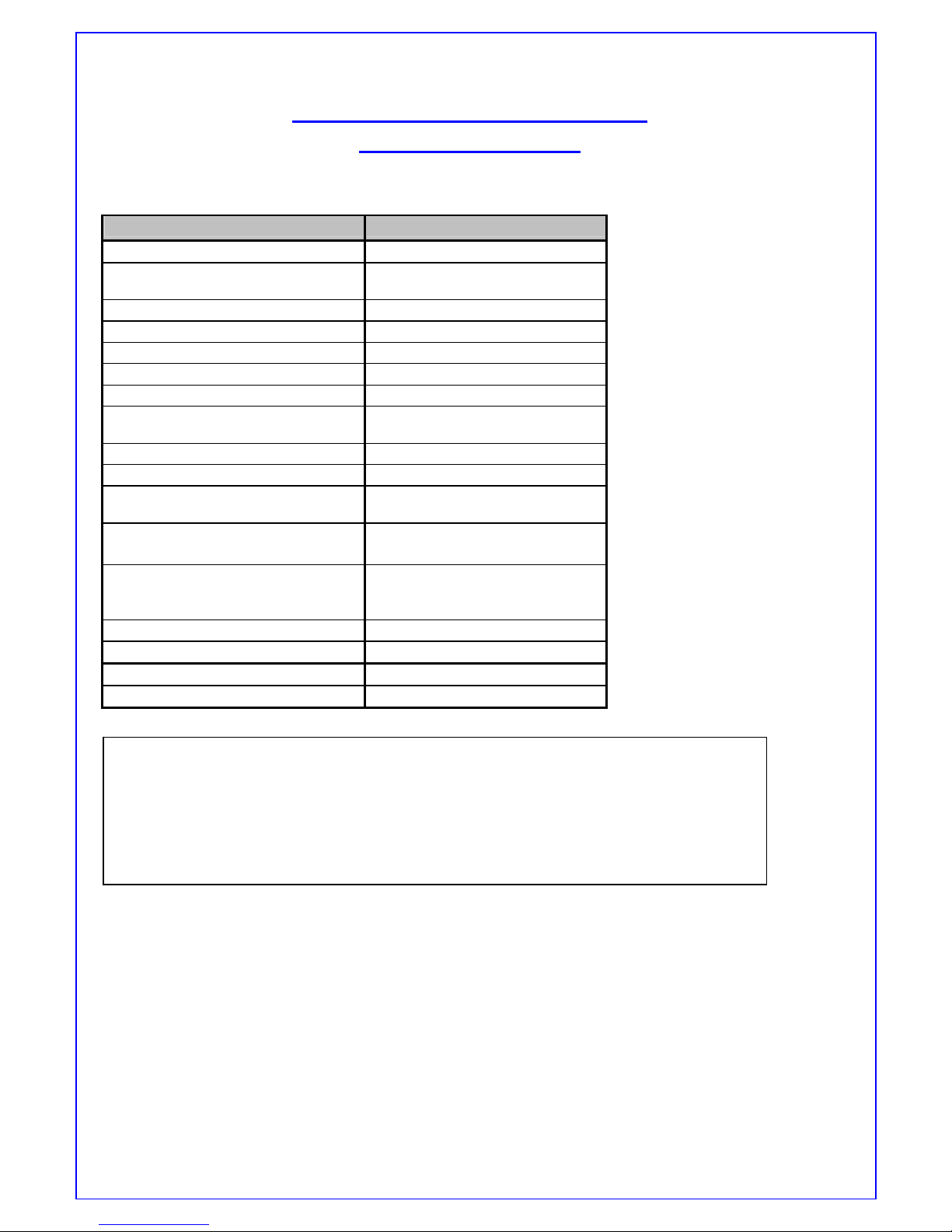
TECHNICAL /FEATURE SPECIFICATION
MODEL 410 L Dlx
Type Frost Free
Capacities (L) total net 410L
Product Dime nsions (mm)
Width 700
Height 1652
Depth 695
Gross Weight (kg) 85
Voltage / Hz 220-240V/5 0- 6 0 Hz
Compressor EMY65HLC
Oil Capacity ISO 22 (280 ml)
Comp. Run Capacitor XS351505XLUB
5 microF/350VAC
PTC Relay PTH7M220MD3
Resistance : 17.6 TO 26.4 @
25°C
Motor Protector 4TM283KFBYY-53
opening temp – 105°C
Closing temp. – 61°C
Trip current – 9.4 A@25°C
Fan motor MI – AE2
2680 rpm , 230V , 50 Hz , 10.5W
Split Diffuser NO
Deodorizer Yes
Number of Shelves 2
Type of Shelves Glass
Humidity Control Yes
RC Illumination ( 8 LED Bank ) Illumination by LED’s
FC Illumination ( 2 LED Bank ) Illumination by LED’s
Bottle Separator YES
Packet Separator YES
Can Rack NO
Egg tray 1 No.
Ice Twister Assembly YES –Plastic
Ice Collector YES
Collapsible Shelf YES
Freezer Door Bins 2
Refrigerator Door Bins 4
Quick Chill Compartment YES
Door lock NO
Handle RECESSED
Roof Rail NO
Cabinet Stop per YES
POT Control in RC compartment YES,8 SETTINGS
Fast Forward Cool Operation NO
Door Alarm YES
Auto Power save mode NO
6
CONTROLS & ELECTRONICS
CONFIGURATION
Product Configuration No frost Dlx
Product Control RC Controlled
Software BEE/Pot based Professional
User interface No
Auto cool mode No
Ice accelerator No
Auto Power save mode No
Door Alarm Yes
Power supply for illumination DC (Linear 220mA)
RC Illumination (8 LED) Yes
FC Illumination (2 LED) Yes
Control Board Yes(Nilgiri BEE)
Defrost heater Yes (Integrated Al tube
275W)
Fan motor 10.5W MI Shaded Pole AC
fan motor
FC Door grounding No
Compressor EMY65HLC
Run Capacitor No
Door Reversibility YES
RATED VOLTAGE : 220-240V,50-60Hz, IPH
VOLTAGE RANGE : 198V – 255V
INPUT WATTAGE : 112W
DEFROST WATTAGE : 275W
FULL LOAD AMPS : 0.5A
7
Top Mount : Deluxe models: -------------------
This refrigerator is managed by an Electronic System, mainly consisting of the components:
• Electronic Control Board (Nilgiri- Dlx (BEE))
• POT (Potentiometer) in case of Dlx (BEE) models only.
• Temperature Sensors {refrigerator, Defrost & POT(Dlx)}
• Compressor ( With Run capacitor)
• Freezer Fan Motor (AC)
• Defrost Heater ( Integrated Al tube 245W)
• Door Open Sensing
These components are described as shown below.
– Electronic Control
The complete operation of this product is done by the Electronic Control, Functions of this models are
fully controlled by the Micro-controller IC which executes the functions according to the needs, turning
the components On or Off through received/managed signals, such as:
- Compressor On/Off
- Defrost Heater On/Off
- Temp setting in refrigerator Compartment, through received signals by the POT along with the RC &
FC Sensors Temp. Feedback.
- Door open sensing / Alarm
- Among many other functions controlled by its software.
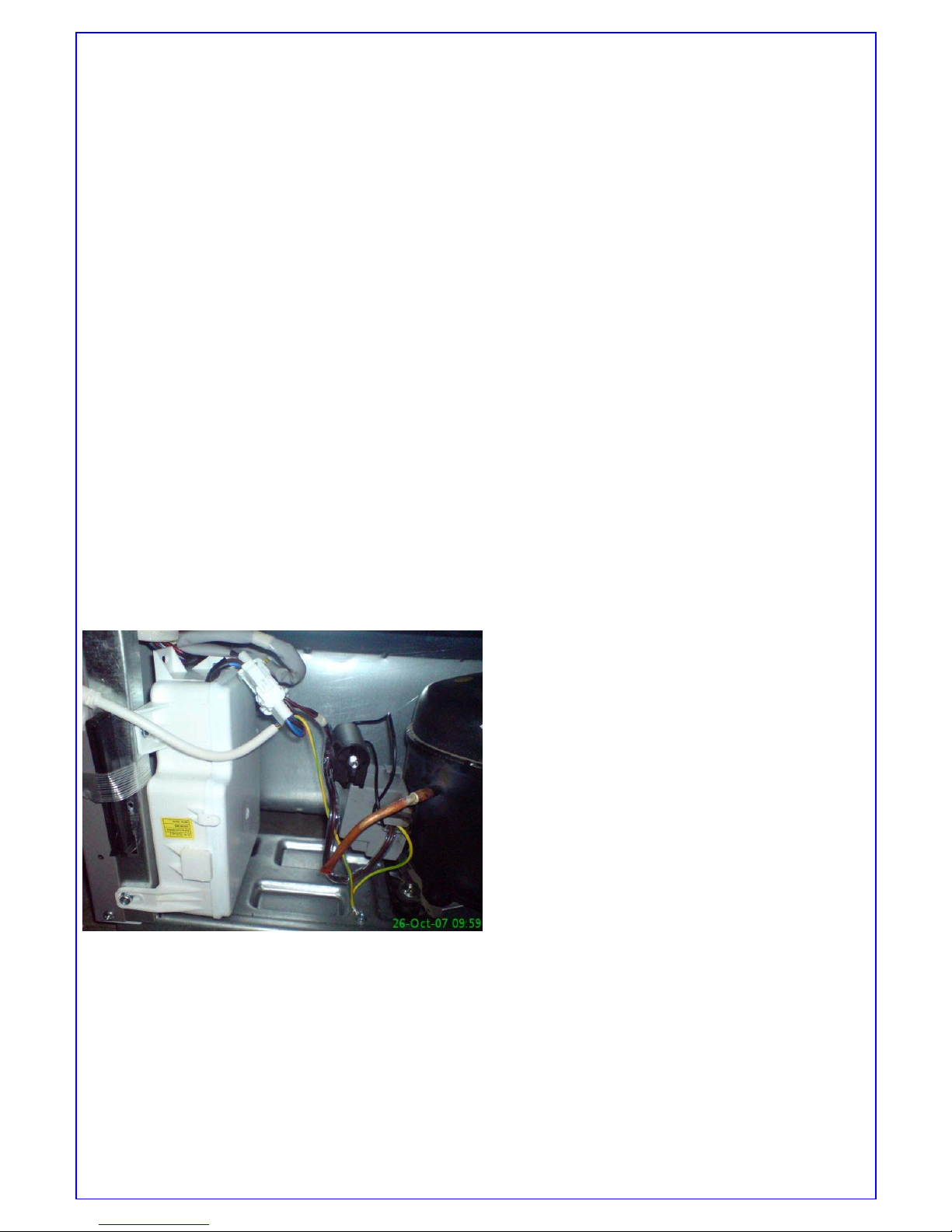
The Electronic Control is located at the rear of the refrigerator, next to the cabinet and besides the
Compressor, inside a plastic box. Cables going inside the product, using connectors that do not permit an
assembling failure do its connection to the mains and its components.
Note: For more details see Wiring Diagram.
8
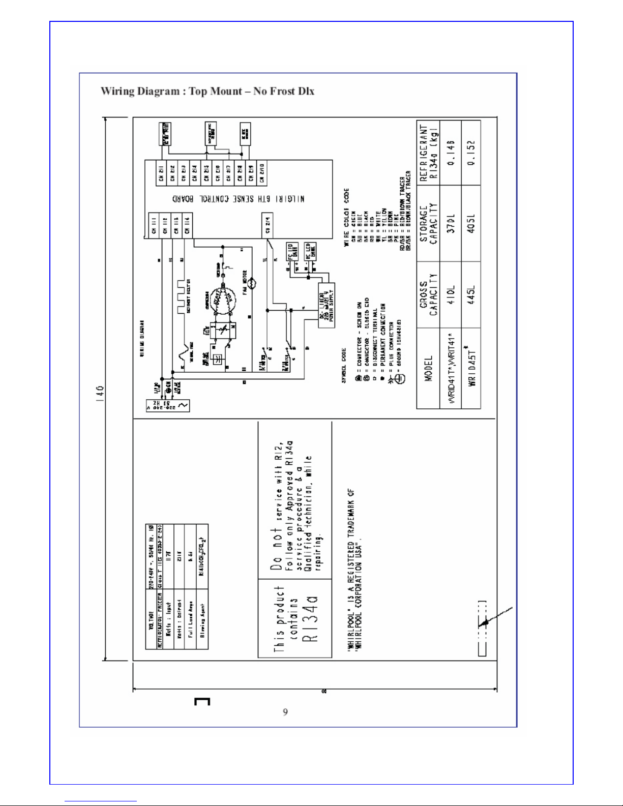
Wiring Diagram : Top Mount – No Frost Dlx
9
 Loading...