

Page 1
FURNACE USER INSTRUCTIONS
FOR PACKAGE GAS ELECTRIC UNITS
Table of Contents
GAS FURNACE SAFETY................................................................1
IMPORTANT NOTE TO THE OWNER REGARDING
PRODUCT WARRANTY.................................................................2
UNIT LOCATION.............................................................................2
UNIT INSTALLATION .....................................................................3
AIR REQUIREMENTS.....................................................................3
THERMOSTAT................................................................................4
PROPANE (LP) GAS INSTALLATIONS ONLY..............................4
OPERATING INSTRUCTIONS.......................................................4
Heating Start-Up .......................................................................... 4
Heating Shutdown .......................................................................5
Cooling Operation........................................................................5
SAFETY CIRCUITS.........................................................................5
Secondary Limit Control ..............................................................5
GAS FURNACE SAFETY
Rollout Limit Control.....................................................................6
Compressor Protection Devices..................................................6
Short-Cycle Protector ..................................................................6
Igniter............................................................................................6
Induced Draft Blower ...................................................................6
Indoor Air Circulator Blower.........................................................6
ROUTINE MAINTENANCE.............................................................6
Annual Inspection.........................................................................6
Replacing or Cleaning the Filter...................................................7
Clean Outside Coil—Qualified Servicer Only...............................7
Condenser, Evaporator and Induced Draft Motors.....................7
Compressor..................................................................................7
SAFETY LABELS ............................................................................8
ASSISTANCE OR SERVICE...........................................................8
Recognize this symbol as a safety precaution.
WARNING
If the information in these instructions is not followed
exactly, a fire or explosion may result causing property
damage, personal injury or loss of life.
— Do not store or use gasoline or other flammable vapors
and liquids in the vicinity of this or any other appliance.
— WHAT TO DO IF YOU SMELL GAS
• Do not try to light any appliance.
• Do not touch any electrical switch; do not use any phone
in your building.
• Immediately call your gas supplier from a neighbor’s
phone. Follow the gas supplier’s instructions.
• If you cannot reach your gas supplier, call the fire
department.
— Installation and service must be performed by a
qualified installer, service agency or the gas supplier.
PLACEHOLDER
FOR
BAR
CODE
WARNING
Hazards or unsafe practices could result in property
damage, product damage, severe personal injury or death.
CAUTION
Hazards or unsafe practices may result in property
damage, product damage, personal injury or death.
WARNING
Should overheating occur or the gas supply fail to shut
off, turn off the manual gas shutoff valve external to the
furnace before turning off the electrical supply.
WARNING
To avoid property damage, personal injury or death, do
not use this furnace if any part of the furnace has been
under water. Immediately call a qualified service technician
to inspect the furnace and to replace any part of the
control system and any gas control having been under
water.
Installer: Affix this manual,
Installation Instructions and
Warranty adjacent to appliance.
Owner: Read and keep all
product literature in a safe place
for future reference.
WPHI-116B
Tradewinds Distributing Company
14610 Breakers Drive
Jacksonville, FL 32258
Page 2
WARNING
Product contains fiberglass wool. Disturbing the insulation
in this product during installation, maintenance or repair
will expose you to fiberglass wool. Breathing this may
cause lung cancer. (Fiberglass wool is known to the State
of California to cause cancer.) Fiberglass wool may also
cause respiratory, skin and eye irritation. To reduce
exposure or for further information, consult material safety
data sheets available from address shown below.
WARNING
This product contains or produces a chemical or
chemicals which may cause serious illness or death and
which are known to the State of California to cause
cancer, birth defects or other reproductive harm.
WARNING
To avoid possible equipment damage, personal injury, fire
or death, the following instructions must be observed
regarding unit location, air requirements and operating
procedures.
WARNING
Heating unit should not be utilized without reasonable,
routine inspection, maintenance and supervision. If the
building in which any such device is located will be
vacant, care should be taken that such device is
routinely inspected, maintained and monitored. In the
event that the building may be exposed to freezing
temperatures and will be vacant, all water-bearing pipes
should be drained, the building should be properly
winterized and the water source closed. In the event
that the building may be exposed to freezing
temperatures and will be vacant, any hydronic coil units
should be drained as well, and, in such case, alternative
heat sources should be utilized.
IMPORTANT NOTE TO THE
OWNER REGARDING
PRODUCT WARRANTY
To receive the 20-Year Heat Exchanger Limited Warranty and the
10-Year Parts Limited Warranty, online registration must be
completed within 60 days of installation. Online registration is not
required in California or Quebec.
Full warranty details and instructions are available at
www.whirlpoolhvac.com.
Your warranty certificate is supplied as a separate document with
the unit installed by your contractor. Read the limited warranty
certificate carefully to determine what is and is not covered. Keep
the warranty certificate in a safe place. If you are unable to locate
the warranty certificate, please contact your installing contractor,
or contact customer service at 1-866-944-7575 to obtain a copy.
To register your unit, go to www.whirlpoolhvac.com. Click on the
Comfort Commitment
center of the home page. Next, click on the Click Here to Register
Your Product link located at the top center of the page, and
complete the forms in the manner indicated.
TM
Warranty link located at the bottom
UNIT LOCATION
This unit is approved only for an outdoor installation. See the
installation instructions for the required clearances to the unit. It
is important that safety measures are taken in the surrounding
area of the unit.
■ Gutters or deflectors must be installed on the roof to prevent
water from shedding on the unit.
■ An area must be available to reach the unit in a clear and
unobstructed path.
■ The unit area and the vicinity of any other gas appliances
must be kept clear and free of combustible materials,
gasoline, and other flammable vapors and liquids.
■ Do not store or use flammable items such as paint, varnish,
or lacquer in the area.
■ The combustion air supply must not be contaminated by
products containing chlorine or fluorine, as they could
corrode the heat exchanger. If you need further information
on this subject, contact your installing dealer or another
qualified servicer.
■ Familiarize yourself with the controls that turn off the gas and
electrical power to the unit.
■ Establish a regular service and maintenance schedule to
ensure efficient and safe operation of the unit.
■ The unit must be placed where no runoff water from higher
ground can collect in the unit.
2
Page 3
UNIT INSTALLATION
Examine the unit installation to determine the following:
■ The flue hood connector is in place and is physically sound
without holes or excessive corrosion.
■ The mounting pad support of the unit is sound.
■ There are no obvious signs of deterioration of the unit.
■ The burner flames are stable, soft and blue, (dust may cause
orange tips but must not be yellow). The flames should
extend directly outward from the burner without curling,
floating, or lifting off. To examine, turn on the electrical power
and gas. Set the room temperature to the maximum setting.
DANGER
CARBON MONOXIDE POISONING HAZARD
Special Warning for Installation of Furnace or Air Handling
Units in Enclosed Areas such as Garages, Utility Rooms or
Parking Areas.
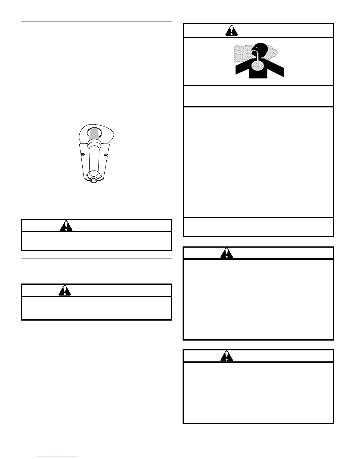
Burner
Check the burner flames for good adjustment, a stable, soft and
blue flame that is not curling, floating or lifting off.
NOTE: If a strong wind is blowing, it may not be possible to
perform the flame inspection.
WARNING
To avoid personal injury or fire, minimum clearances to
combustible surfaces must be followed.
AIR REQUIREMENTS
WARNING
To avoid property damage, personal injury or death,
sufficient fresh air for proper combustion and ventilation
of flue gases must be supplied.
Since the gas/electric unit is installed completely in the outdoors,
the depletion of combustion air is highly improbable. To ensure
an adequate supply of combustion air, do not allow the
combustion air inlet or the flue hood outlet to become blocked by
leaves, snow, rubbish, or insect (wasps) nests. Never block the
condensing unit section in the winter with covers. Blocking of this
section would prevent an adequate amount of combustion air
from reaching the furnace section.
Great care has been taken in the design and manufacture of your
unit to provide for your comfort and safety. Be aware of the
possibility that some problems with your unit or other gas-fired
appliances could cause flue gases to be present in your building.
These flue gases could include carbon monoxide.
Carbon monoxide producing devices (such as an
automobile, space heater, gas water heater, etc.) should
not be operated in enclosed areas such as unventilated
garages, utility rooms or parking areas because of the
danger of carbon monoxide (CO) poisoning resulting from
the exhaust emissions. If a furnace or air handler is
installed in an enclosed area such as a garage, utility room
or parking area and a carbon monoxide producing device is
operated therein, there must be adequate, direct outside
ventilation.
This ventilation is necessary to avoid the danger of CO
poisoning which can occur if a carbon monoxide producing
device continues to operate in the enclosed area. Carbon
monoxide emissions can be (re)circulated throughout the
structure if the furnace or air handler is operating in any
mode.
CO can cause serious illness including permanent brain
damage or death.
WARNING
Personal injury or death from
exposure to carbon monoxide. Carbon
colorless and odorless gas produced when fuel is not
burned completely or when the flame does not receive
sufficient oxygen. Be aware of
which indicate conditions that may result in carbon
monoxide or that carbon monoxide may be present:
-Headaches, nausea, dizziness, flu-like symptoms
-Excessive humidity, heavily-frosted windows, a moist,
clammy feeling in the home
-Fireplace smoke will not draw up the chimney
-Flue gases will not draw up the appliance vent pipe
asphyxiation can result from
monoxide or CO is
these air starvation signals
WARNING
To prevent property damage or serious personal injury
due to fire or explosion caused by a propane gas leak,
install a gas detecting warning device.
If the propane gas unit is installed in an excavated area
or a confined space, a warning device is required due to:
-Propane gas is heavier than air and any leaking gas
can settle in any low areas or confined spaces.
-Propane gas odorant may fade, making the gas
undetectable except with a warning device.
3
Page 4
WARNING
C
An undetected gas leak can create a danger of explosion
or fire. The unit and its gas connections must be leak
tested before placing in operation.
PROPANE (LP) GAS
INSTALLATIONS ONLY
For units operating on propane gas, please review the following
warnings before use.
THERMOSTAT
This unit will not operate properly without a good quality,
correctly installed thermostat. It is very important that the
thermostat be located where it can best “sense” the average
room temperature.
Be sure that the thermostat is not exposed to hot or cold drafts or
to hot or cold spots on the wall, such as those received from
outside walls, walls with pipes inside, or from openings into the
attic.
No matter what type or style of thermostat is used, thermostat
operation is basically the same. The most widely used types will
control both heating and cooling functions and will have a fan
switch with AUTO and ON settings. On AUTO, the circulating air
blower will cycle on/off. When the switch is set to ON, the
circulating air blower will run constantly.
IMPORTANT NOTE: To avoid the possibility of damage to the
unit heat exchanger, do not set the fan switch to ON (constant fan
operation) during the heating season without first consulting the
installer of the unit or another qualified servicer.
There are thermostats that automatically switch from Heating to
Cooling, or with night setbacks. The night setback, or multiple
setback type, will lower the temperature at night or during the
day when the building is unoccupied.
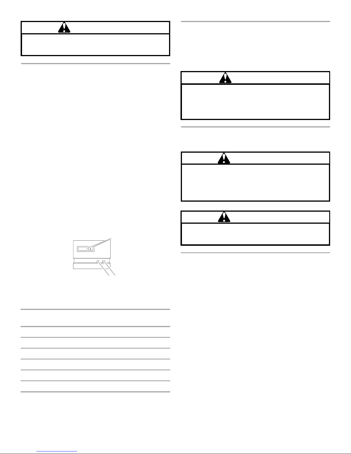
Typical Thermostat
A
WARNING
To avoid property damage, personal injury or death due to
explosion or fire, install a gas detecting warning device.
Since the odorant in propane gas can be reduced by iron
oxide (rust), a gas detecting warning device is the only
reliable method to detect propane gas leaks.
Goodman 85
OPERATING INSTRUCTIONS
WARNING
To avoid property damage, personal injury or death due
to fire, do not remove any internal compartment covers
or attempt any adjustment. Electrical components are
contained in both compartments. Contact a qualified
service agent at once if an abnormal flame appears.
WARNING
An undetected gas leak can create a danger of explosion
or fire. The unit and its gas connections must be leak
tested before placing in operation.
Goodman 103
B
A. Cool/Heat temperature control dials
B. Fan switch
System
Switch
OFF AUTO None
COOL AUTO System only cools; fan cycles off and on.
COOL ON System only cools; fan runs all the time.
HEAT AUTO System only heats; fan cycles off and on.
HEAT ON System only heats; fan runs all the time.
OFF ON No heating or cooling; fan runs all the time.
Fan
Switch Action
C. Cool/Heat switch
Heating Start-Up
To put your unit into operation, follow the steps listed below.
1. Close the external manual gas shutoff valve.
2. Turn off the electrical power to the unit.
3. Set the room thermostat to the lowest possible setting.
4. Remove the heat exchanger door on the side of the unit by
removing the screws.
5. This unit is equipped with an ignition device which
automatically lights the burner.
NOTE: Do not try to light the burner by hand.
6. Move the gas control switch to the OFF position.
NOTE: Do not use excessive force.
7. Wait 5 minutes to clear out any gas. Then check for a gas
odor, including near the floor as some types of gas are
heavier than air.
8. If a gas odor is detected following the 5-minute waiting
period, immediately leave the building and call your gas
supplier or the fire department.
4
Page 5
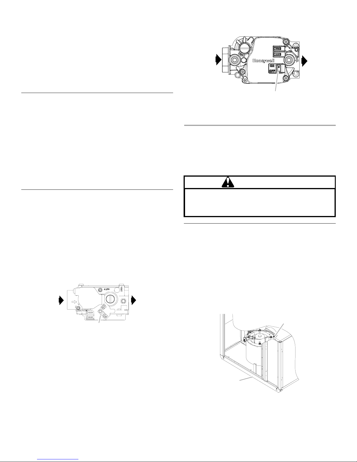
9. If no gas odor is detected after 5 minutes, move or rotate the
C
C
furnace’s gas control valve On/Off switch to the ON position.
NOTE: The switch should turn easily. Do not use excessive
force.
10. Reinstall the burner compartment door.
11. Open the external manual gas shutoff valve.
12. Turn on the electrical power to the unit.
13. Adjust the thermostat to a setting above room temperature.
14. After the burners are lit, set the thermostat to the desired
temperature.
Heating Shutdown
To shut down operation, follow the steps listed below.
1. Set the thermostat to the lowest setting.
2. Turn OFF electrical power to the unit.
3. Remove the heat exchanger door on the side of the unit by
removing the screws.
4. Move the gas control switch to the OFF position.
NOTE: Do not use excessive force.
5. Close the external manual gas shutoff valve.
6. Reinstall the heat exchanger door.
7. If cooling and/or air circulation is desired, turn ON the
electrical power.
Cooling Operation
Cooling operation may be obtained as follows:
1. Place the room thermostat selector switch in the COOL
position (or AUTO, if available, and if automatic changeover
from cooling to heating is desired).
2. Set the room thermostat to the desired temperature.
3. If the cooling system does not energize, wait 5 minutes. The
system start-up may be delayed by the short-cycle protector
feature of the ignition control board. Check the manual reset
devices on the rollout limit switch, as described in this
manual.
Gas Control Valve—White-Rodgers 36G22
A
Gas Control Valve—Honeywell Model VR8215—Single
Stage
A
B
A. Inlet
B. On/Off selector switch
C. Outlet
SAFETY CIRCUITS
A number of safety circuits are employed to ensure safe and
proper unit operation. These circuits serve to control any
potential safety hazards and, provide inputs in the monitoring and
diagnosis of abnormal operation.
WARNING
If the secondary limit control should open, the reason
must be determined before the control resets. The
electrical power must be disconnected before any panel
is removed or maintenance is performed.
Secondary Limit Control
The secondary limit control is located on the blower housing and
monitors blower compartment temperatures. It is a normallyclosed (electrically), automatic-reset, temperature-activated
sensor. This limit guards against overheating as a result of
insufficient conditioned air passing over the heat exchanger. It
de-energizes the gas control valve if the blower fails.
NOTE: If the power to the unit is interrupted during the heating
cycle, it may cause the secondary limit control to trip. Once the
blower compartment temperature drops below the limit reset
temperature, the limit will automatically reset.
Secondary Limit Control
B
A. Inlet
B. On/Off selector switch
C. Outlet
A
B
A. Secondary limit control
B. Back of unit
5
Page 6
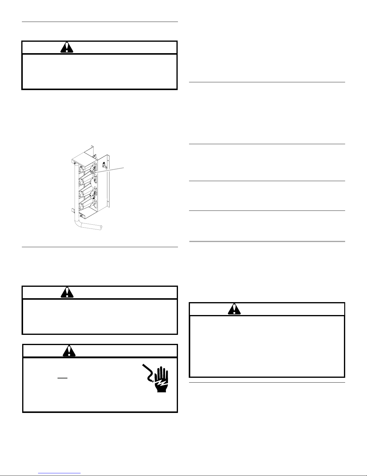
Rollout Limit Control
A
WARNING
The cause of the rollout protection device opening must
be investigated by a qualified servicer before any attempt
is made to reset the rollout protection device and turn
the unit back on. The electrical power must be
disconnected before either front panel is removed.
The rollout limit is a normally-closed (electrically), manual-reset,
temperature-activated sensor. It is mounted on the burner
bracket and monitors the burner flame. If there is an improper
draw of burner flames into the heat exchanger, the rollout limit
will detect it and shut off gas flowing to the burners. Contact a
qualified servicer to check the unit before resetting this device.
Rollout Protection on Burner Bracket
Goodman 105
If, during a call for cooling, the indoor fan runs and circulates
room temperature air while the compressor and outdoor fan do
not operate:
1. Wait 5 minutes, as a protection device may be holding the
compressor off.
2. Check the room thermostat to see if it is correctly set.
3. If the room thermostat is correctly set, call a qualified servicer
to determine if one of the compressor protection devices has
opened.
Short-Cycle Protector
A short-cycle protector is built into the ignition control. Each time
the compressor is off for less than 3 minutes, the short-cycle
protector will delay compressor start-up for up to 3 minutes. This
protects the compressor from improper operation.
NOTE: These units are not designed to provide mechanical
cooling at outdoor temperatures below 50°F (10ºC). If low
ambient cooling is needed, consult a qualified servicer.
Igniter
The unit has an electronic ignition device which lights the burners
automatically.
NOTE: Never try to light the burners by hand.
Induced Draft Blower
This unit has an induced draft blower to exhaust combustion
products.
A. Rollout protection
Compressor Protection Devices
This gas/electric package unit includes components which are
designed to protect the compressor against abnormal operating
conditions.
WARNING
To prevent personal injury or death, always disconnect
the electrical power before inspecting or servicing the
unit. Since all of the compressor protection devices reset
automatically, the contactor and outdoor fan may be
energized when reset.
WARNING
HIGH VOLTAGE!
Disconnect ALL power before servicing.
Multiple power sources may be present.
Failure to do so may cause property damage,
personal injury or death.
NOTE: The operation of the indoor blower will not be affected by
any compressor protection devices.
Indoor Air Circulator Blower
Keep the blower access door panel in place except for inspection
and maintenance.
ROUTINE MAINTENANCE
If you perform maintenance on the unit yourself, remember that
certain mechanical and electrical knowledge, skills and tools are
required to perform unit maintenance. Personal injury or death
may result If you are not properly trained. You should call your
installing dealer or place of purchase if you are uncertain about
your ability to perform maintenance.
WARNING
To avoid personal
the following procedures must be followed exactly in
sequence before inspecting the unit:
1. Turn Off gas by closing external gas shutoff valve to
the unit.
2. Turn Off electrical power by opening unit power
disconnect.
3. If the unit has been operating, wait 15 minutes for it to
cool.
Your package unit should be inspected by a qualified installer, or
service agency at least twice every year. This check should be
performed before the heating and cooling seasons begin. This
will ensure that adequate combustion air is being drawn and the
vent system is working properly. Particular attention should be
paid to the following items. Repair as necessary.
injury or death due to explosion or fire,
Annual Inspection
6
Page 7
■ Check physical support of the unit. Check that it is sound
without any sagging, cracks, or gaps, around the base.
■ Check for obvious signs of deterioration of the unit.
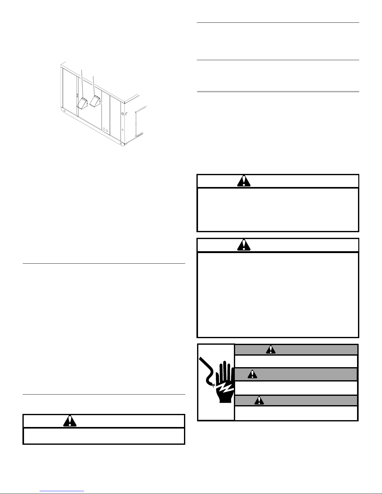
■ Flue hood and combustion air inlet. Check for blockage
(wasp nest, etc.) and corrosion.
Condenser, Evaporator and Induced Draft Motors
Bearings on the air circulating blower motor, condenser motor
and the combustion fan motor are permanently lubricated. No
additional oiling is required.
A
B
A. Combustion air inlet
B. Flue hood
■ Return air connection. Check for physical soundness and
ensure that the connection is firmly sealed to the package
unit casing.
■ Heat exchanger. Check for corrosion and/or obstructions
within the heat exchanger passageways.
■ Burners. Check for proper ignition, burner flame, and flame
sense.
■ Wiring. Check electrical connections for tightness and/or
corrosion. Check wires for damage.
■ Filters. Check that filters are clean and in the proper
placement in the unit or duct system.
■ Louvers. Inspect air inlet louvers inside the heat exchanger
compartments. Ensure the area is clean and free of dirt and
debris.
Replacing or Cleaning the Filter
IMPORTANT NOTE: Never operate unit without a filter installed
as dust and lint will build up on internal parts resulting in loss of
efficiency, equipment damage and possible fire.
A return air filter is not supplied with this unit; however, there
must be a means of filtering the return air. The filter(s) may be
located in the return air duct(s). Consult with your installing dealer
for the actual location of the return air filter(s) in your unit.
A dirty filter is the most common cause of inadequate heating or cooling
performance. Filter inspection should be made at least every 2 months;
more often if necessary because of local conditions and usage.
Dirty throwaway filters should be discarded and replaced with a new,
clean filter. Dirty permanent filters should be washed with water,
thoroughly dried and sprayed with a filter adhesive before being
reinstalled. Filter adhesives may be found at many hardware stores.
Permanent filters should last several years. However, should one
become worn or uncleanable, it should be replaced.
When installing a new filter or reinstalling an old one, always make
certain the airflow arrows on the filter point in the proper direction.
Clean Outside Coil—Qualified Servicer Only
WARNING
To avoid personal
disconnect the electrical switch before cleaning the coil(s).
injury or death due to electrical shock,
Compressor
The compressor motor is hermetically sealed and does not
require additional oiling.
SAFETY LABELS
NOTE: If safety labels are missing or illegible, contact the
installing dealer.
To obtain the proper safety labels, the model and serial number of
the unit must be supplied. These numbers are recorded on the
nameplate of the unit. For your convenience, record this
information here:
Model Number: _________________________________________________
Serial Number:__________________________________________________
WARNING
If not installed, operated and maintained in accordance
with manufacturer's instructions, this product could expose
you to substances in fuel or from fuel combustion which
can cause death or serious illness and which are known
to the State of California to cause cancer, birth defects
or other reproductive harm.
WARNING
Heating units should not be utilized without reasonable,
routine inspection, maintenance and supervision. If the
building in which any device is located will be vacant,
care should be taken that such device is routinely
inspected, maintained and monitored in the event that the
building may be exposed to freezing temperatures and
will be vacant. All water-bearing pipes should be drained.
The building should be properly winterized, and the water
source closed. In the even that the building may be
exposed to freezing temperatures and will be vacant, any
hydronic coil units should be drained as well and, in such
case, alternative heat sources should be utilized.
WARNING
HAZARD OF ELECTRIC SHOCK
DISCONNECT THE ELECTRIC POWER BEFORE SERVICING.
AVERTISSEMENT
DANGER DE CHOC ÉLETRIQUE
DECONNECTER LE CIRCUIT D'ALIMENTATION ÉLECTRIQUE
AVANT L'ENTRETIEN.
ADVERTENCIA
PELIGRO DE CHOQUE ELÉCTRICO
DESCONECTE LA ENERGÍA ELÉCTRICA ANTES DEL
MANTENIMIENTO.
The coil, with the outside air flowing over it, should be inspected
annually and cleaned as frequently as necessary to keep the
finned areas free of leaves, grass, seeds and debris.
7
Page 8
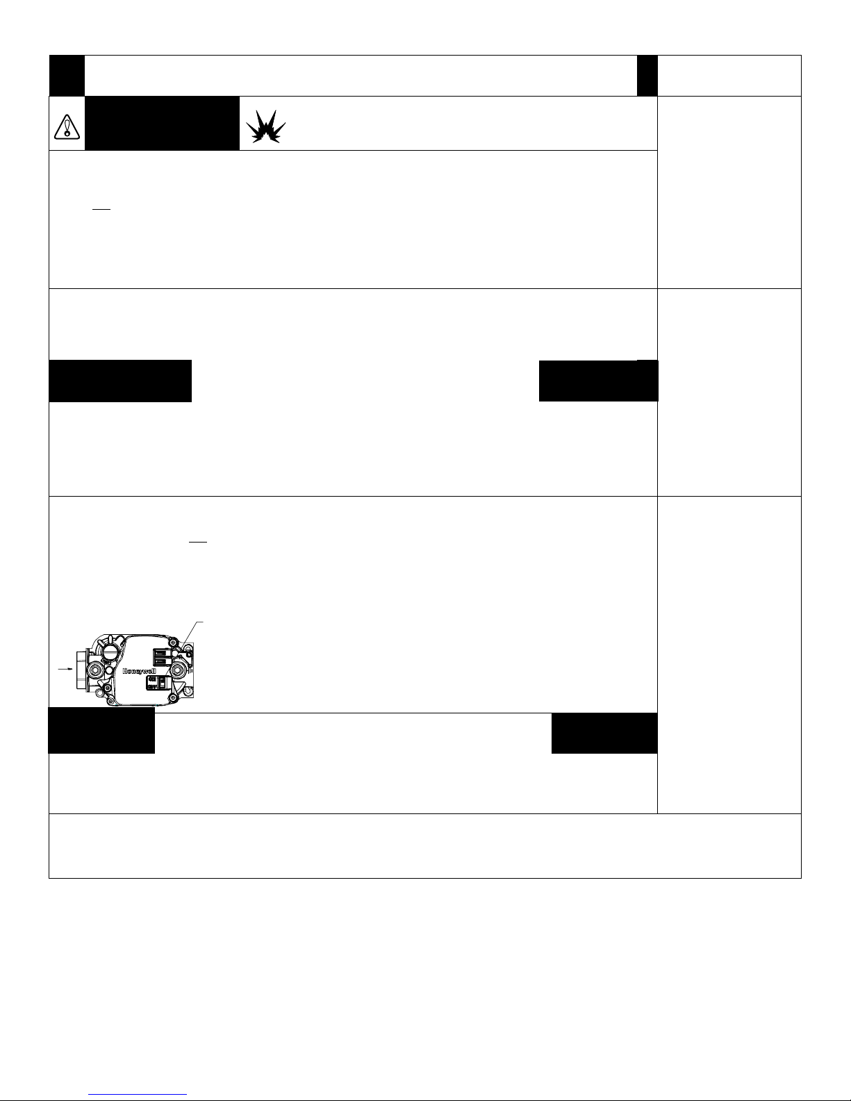
FOR YOUR SAFETY READ BEFORE OPERATING
W
©
WARNING
A. This appliance does not have a pilot. It
is equipped with an ignition device
which automatically lights the burner.
try to light the burner by hand.
Do not
B. BEFORE OPERATING, smell all around
the appliance area for gas. Be sure to
smell next to the floor because some
gas is heavier than air and will settle on
the floor.
WHAT TO DO IF YOU SMELL GAS
■ Do not try to light any appliance.
■
Do not touch any electrical switch; do
not use any phone in your building.
OPERATING INSTRUCTIONS
1. STOP! Read the safety information
above on this label.
2. Set the thermostat to lowest setting.
3. Turn off all electric power to the
appliance.
6. This appliance is equipped with an
ignition device which automatically
lights the burner. Do not
burner by hand.
7. Remove control access panel.
8. Move the gas control switch or knob to
“OFF.”
try to light the
GAS CONTROL
SWITCH SHOWN
IN "ON" POSITION
TO TURN OFF GAS TO APPLIANCE
1. Set the thermostat to lowest setting.
2. Turn off all electric power to the
appliance if service is to be performed.
If you do not follow these instructions exactly, a fire or explosion
may result causing property damage, personal injury or loss of
life.
■ Immediately call your gas supplier from a neighbor’s
phone. Follow the gas supplier’s instructions.
■ If you cannot reach your gas supplier, call the fire
department.
C. Use only your hand to push in or turn the gas control lever.
Never use tools. If the lever will not push in or turn by hand,
don’t try to repair it; call a qualified service technician. Force
or attempted repair may result in a fire or explosion.
D. Do not use this appliance if any part has been underwater.
Immediately call a qualified service technician to inspect the
appliance and to replace any part of the control system and
any gas control which has been underwater.
4. Wait five (5) minutes to clear out any gas. Then smell for gas,
including near the floor. If you then smell gas, STOP! Follow
“B” in the safety information above on this label. If you don’t
smell gas, go to next step.
5. Move the gas control switch or knob to “ON.”
9. Replace control access panel.
10. Turn on all electric power to the appliance.
11. Set thermostat to desired setting.
12. If the appliance will not operate, follow the instructions “To
Turn Off Gas To Appliance” and call your service technician or
gas company.
3. Remove control access panel.
4. Move the gas control switch or knob to “OFF.” Do not force.
5. Replace control access panel.
WARNING:
installation, adjustment,
alteration, service or
maintenance can cause
injury or property damage.
Refer to the user’s
information manual
provided with this furnace.
For assistance or
additional information,
consult a qualified
installer, service agency or
the gas supplier
This furnace must be
installed in accordance
with the manufacturer’s
instructions and local
codes. In the absence of
local codes, follow the
National Fuel Gas Code,
ANSI Z223.1.
WARNING: If not
installed, operated and
maintained in
accordance with the
manufacturer’s
instructions, this product
could expose you to
substances in fuel
combustion which can
cause death or serious
illness and which are
known to the State of
California to cause
cancer, birth defects or
othe reproductive harm.
This product contains
fiberblass insulation.
Fiberglass insulation
contains a chemical
known by the State of
California to cause
cancer.
Improper
FOR YOUR SAFETY Do not store or use gasoline or other flammable
vapors and liquids in the vicinity of this or any other appliance.
If you need further assistance, you can write to the below
address with any questions or concerns:
Tradewinds Distributing Company, LLC
14610 Breakers Drive
Jacksonville, FL 32258
PHI-116B
2010. All rights reserved.
Manufactured under license by Tradewinds Distributing Company, LLC, Jacksonville, Florida.
Warranty provided by manufacturer. All other trademarks are owned by their respective companies.
ASSISTANCE OR SERVICE
Please include a daytime phone number in your correspondence.
Or call toll free: 1-866-944-7575.
®Registered Trademark/TM Trademark of Whirlpool, U.S.A.,
Printed in U.S.A.
4/10
 Loading...