

Whirlpool WOSA2EC0HZ01, WOSA2EC0HZ00, WOSA2EC0HN01, WOSA2EC0HN00, WOS72EC0HV01 Installation Guide [en, fr]
...Page 1

INSTALLATION INSTRUCTIONS
IMPORTANT:
Sa
IMPOR
À conserver pour consultation par l'inspecteur local des installations électriques.
27" (68.6 CM) AND 30" (76.2 CM) ELECTRIC
SINGLE AND DOUBLE BUILT-IN OVEN
FLUSH INSTALLATION KIT
INSTRUCTIONS D’INSTALLATION
ENSEMBLE D’INSTALLATION EN AFFLEUREMENT
POUR FOUR ÉLECTRIQUE ENCASTRÉ SIMPLE ET
DOUBLE DE27"(68,6 CM) ET 30" (76,2 CM)
Flush Installation Kit Part Number
Ensemble d'installation en
affleurement référence
W11173681 27” (68.6 cm), white WOS51EC7HW, WOD51EC7HW
W11173683 30” (76.2 cm), white
W11173685 27” (68.6 cm), black
W11173691 30” (76.2 cm), black
W11173693 27” (68.6 cm), stainless steel
W11123003 30” (76.2 cm), stainless steel
W11173700 27” (68.6 cm), black stainless WOS72EC7HV, WOD77EC7HV
W11173703 30” (76.2 cm), black stainless WOS72EC0HV, WOD77EC0HV
W11123005 30” (76.2 cm), bronze WOSA2EC0HN, WODA7EC0HN
Size and Color
Dimensions et couleur
UL Listed for Model Numbers
Homologation UL pour les modèles
numéro
WOS51EC0HW, WOD51EC0HW,
WOS72EC0HW, WOD77EC0HW
WOS51EC7HB, WOD51EC7HB,
WOS72EC7HB, WOD77EC7HB
WOS51EC0HB, WOD51EC0HB,
WOS72EC0HB, WOD77EC0HB
WOS51EC7HS, WOD51EC7HS,
WOS72EC7HS, WOD77EC7HS
WOS51EC0HS, WOD51EC0HS,
WOS72EC0HS, WOD77EC0HS,
WOS97EC0HZ, WOSA2EC0HZ,
WOD97EC0HZ, WODA7EC0HZ
Table of Contents/Table des matières
BUILT-IN OVEN SAFETY ................................................................2
INSTALLATION REQUIREMENTS
Tools and Parts
Location Requirements
INSTALLATION INSTRUCTIONS
Prepare Built-In Oven
Remove Oven Door(s)
Replace Oven Door(s)
Positioning Oven Feet
Replace Plastic Spacers
Install Oven
Install Deector Kit Bracket
Complete Installation
.............................................................................2
................................................................2
...................................................................5
..................................................................5
..................................................................6
..................................................................6
..............................................................7
...................................................................................8
...................................................................9
.................................................2
...................................................5
.........................................................9
SÉCURITÉ DU FOUR ENCASTRÉ
EXIGENCES D’INSTALLATION
Outillage et pièces
Exigences d’emplacement
INSTRUCTIONS D’INSTALLATION
Préparation du four encastré
Dépose de la/des porte(s) du four
Réinstallation de la/des porte(s) du four
Positionnement des pieds du four
Remplacement des cales d’espacement en plastique
Installation du four
Installation du support de la trousse du déecteur
Achever l’installation
......................................................................11
......................................................................17
..................................................................19
..............................................10
...................................................11
.........................................................11
.............................................14
.....................................................14
.............................................14
.............................................15
....................................14
.............16
...................18
ve for local electrical inspector's use.
TANT :
W11115048A
Page 2
BUILT-IN OVEN SAFETY
Your safety and the safety of others are very important.
We have provided many important safety messages in this manual and on your appliance. Always read and obey all safety
messages.
This is the safety alert symbol.
This symbol alerts you to potential hazards that can kill or hurt you and others.
All safety messages will follow the safety alert symbol and either the word “DANGER” or “WARNING.”
These words mean:
You can be killed or seriously injured if you don't immediately
DANGER
WARNING
All safety messages will tell you what the potential hazard is, tell you how to reduce the chance of injury, and tell you what can
happen if the instructions are not followed.
follow instructions.
You
can be killed or seriously injured if you don't
instructions.
follow
INSTALLATION REQUIREMENTS
Tools and Parts
Gather the required tools and parts before starting installation.
Read and follow the instructions provided with any tools listed here.
Tools Needed
■ Phillips screwdriver
■ Measuring tape
■ Drill (for wall cabinet installations)
1
■
/8" (3 mm) drill bit (for wall cabinet installations)
■ Level
■ Flat-blade screwdriver
Parts Needed
■ #8-14 x 1" screws - (2) single ovens, (4) double ovens
included with built-in oven
■ (2) #8-18 x
built-in oven
■ (4) #8-18 x
built-in oven
■ Bottom vent included with built-in oven
■ (2) feet double oven included with built-in oven
■ (2) front feet double oven included with built-in oven
Parts Supplied
■ Deector bracket
3
/8" screws - bottom vent included with
3
/8" screws - double oven feet included with
Location Requirements
IMPORTANT: Observe all governing codes and ordinances.
NOTE: Refer to the following “Location Requirements” and the
“Location Requirements” section of the Installation Instructions
provided with your built-in oven.
■ Cabinet opening dimensions that are shown must be used.
Given dimensions provide minimum clearance with oven.
■ Recessed installation area must provide complete enclosure
around the recessed portion of the oven.
■ Oven support surface must be solid, level, and ush with
bottom of cabinet cutout.
■ Floor must be able to support a single oven weight of
129lbs (59 kg) for 27" (68.6 cm) models or 154 lbs (70 kg)
for30"76.2 cm) models.
■ Floor must be able to support a double oven weight of
251lbs (114 kg) for 27" (68.6 cm) models or 288 lbs (131 kg)
for 30" (76.2 cm) models.
IMPORTANT: To avoid damage to your cabinets, check with
your builder or cabinet supplier to make sure that the materials
used will not discolor, delaminate, or sustain other damage. This
oven has been designed in accordance with the requirements
of UL and CSA International and complies with the maximum
allowable wood cabinet temperatures of 194°F (90°C).
■ Plastic spacers - (2) single ovens, (4) double ovens
■ #8-18 x
(76.2 cm) models
2
1
/8" screws - (2) for 27" (68.6 cm) models), (4) for 30"
Page 3
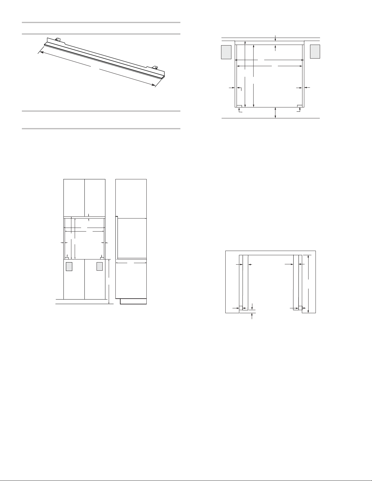
Deflector Bracket Dimensions
AA
Single Ovens Undercounter - Flush Installations
(without cooktop installed above)
A
27" (68.6 cm) Models
A. 2615/16" (68.4 cm) overall width
30" (76.2 cm) Models
15
A. 29
/16" (76.0 cm) overall width
Cabinet Dimensions - Single Ovens,
Flush Installations
A 25" (63.5 cm) minimum cutout depth is required.
These dimensions will result in a 1/4" (6 mm) reveal on the top,
a1/4" (6 mm) reveal on the sides, and a 1/8" (3 mm) reveal on
thebottom of the wall oven.
The front face of the cleats and platform will be visible and
should be treated as a nished surface.
Single Ovens Installed in Cabinet - Flush Installation
A
B
C
D
E
F
G
F
G
A
B
A
C
D
E
F
G
G
H
Front View
27" (68.6 cm) Models
A. Recommended junction box
location
3
B.
/4" (19 mm) top cleat*
1
C. 27
/4" (69.2 cm) minimum
width of ush inset cutout
7
D. 25
/8" (65.7 cm) minimum
width of opening
1
E. 29
/4" (74.3 cm) minimum
height of ush inset cutout
2
F. 28¹/
" (72.4 cm)
recommended cutout height
5
G.
/8" (17 mm) side cleat*
1
H.
/2" x 2" (13 mm x 51 mm)
spacer the entire depth of
the cabinet*
5
I. 4
/8" (11.7 cm) bottom of
cutout to oor
* Cleats and spacers must be recessed 13/8" (3.5 cm) from the
front of the cabinet.
H
I
30" (76.2 cm) Models
A. Recommended junction box
location
3
B.
/4" (19 mm) top cleat*
4
C. 30¹/
" (76.8 cm) minimum
width of ush inset cutout
7
D. 28
/8" (73.3 cm) minimum
width of opening
1
E. 29
/4" (74.3 cm) minimum
height of ush inset cutout
1
F. 28
/2" (72.4 cm)
recommended cutout height
11
G.
/16" (17 mm) side cleat*
1
H.
/2" x 2" (13 mm x 51 mm)
spacer the entire depth of
the cabinet*
5
I. 4
/8" (11.7 cm) bottom of
cutout to oor
H
H
Front View Side View
27" (68.6 cm) Models
3
A.
/4" (19 mm) top cleat*
1
B. 27
/4" (69.2 cm) minimum
width of ush inset cutout
7
C. 25
/8" (65.7 cm) minimum
width of opening
1
D. 29
/4" (74.3 cm) minimum
height of ush inset cutout
1
E. 28
/2" (72.4 cm)
recommended cutout height
11
F.
/16" (17 mm) side cleat*
1
G.
/2" x 2" (13 mm x 50.8 mm)
spacer the entire depth of the
cutout*
H. Recommended junction box
location
5
I. 4
/8" - 32" (11.7 cm -
81.3cm) bottom of cutout to
oor
J. 25" (63.5 cm) minimum depth
of cutout
J
I
30" (76.2 cm) Models
3
A.
/4" (19 mm) top cleat*
1
B. 30
/4" (76.8 cm) minimum
width of ush inset cutout
7
C. 28
/8" (73.3 cm) minimum
width of opening
1
D. 29
/4" (74.3 cm) minimum
height of ush inset cutout
1
E. 28
/2" (72.4 cm)
recommended cutout height
11
F.
/16" (17 mm) side cleat*
1
G.
/2" x 2" (13 mm x 51 mm)
spacer the entire depth of
the cutout*
H. Recommended junction box
location
5
I. 4
/8" - 32" (11.7 cm -
81.3cm) bottom of cutout
to oor
J. 25" (63.5 cm) minimum
depth of cutout
B
C
D
D
Top View
27" (68.6 cm) Models
1
A.
/2" x 2" (13 mm x 51 mm)
spacer the entire depth of
the cutout*
B. 25" (63.5 cm) depth of
cutout
3
C. 1
/8" (3.5 cm) recess from
front of cabinet
11
D.
/16" (17 mm) side cleat*
30" (76.2 cm) Models
1
A.
/2" x 2" (13 mm x 51 mm)
spacer the entire depth of
the cutout*
B. 25" (63.5 cm) depth of
cutout
3
C. 1
/8" (3.5 cm) recess from
front of cabinet
11
D.
/16" (17 mm) side cleat*
* Cleats and spacers must be recessed 13/8" (3.5 cm) from
thefront of the cabinet.
* Cleats and spacers must be recessed 13/8" (3.5 cm) from the
front of the cabinet.
3
Page 4
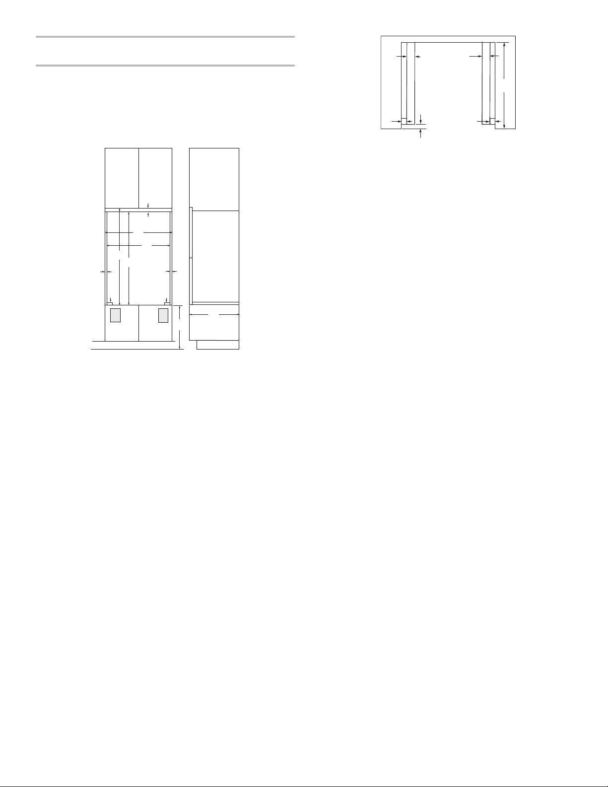
Cabinet Dimensions - Double Ovens,
AA
Flush Installations
A 253/8" (64.4 cm) minimum cutout depth is required.
These dimensions will result in a 1/4" (6 mm) reveal on the top,
a1/4" (6 mm) reveal on the sides, and a 1/8" (3 mm) reveal on
thebottom of the wall oven.
The front face of the cleats and platform will be visible and
should be treated as a nished surface.
Double Ovens Installed in Cabinet - Flush Installations
A
B
C
D
F
E
F
G G
B
C
D
D
Top View
27" (68.6 cm) Models
1
A.
/2" x 2" (13 mm x 51 mm)
spacer the entire depth of
the cutout*
3
B. 25
/8" (64.4 cm) depth of
cutout
3
C. 1
/8" (3.5 cm) recess from
front of cabinet
11
D.
/16" (17 mm) side cleat*
30" (76.2 cm) Models
1
A.
/2" x 2" (13 mm x 51 mm)
spacer the entire depth of
the cutout*
3
B. 25
/8" (64.4 cm) depth of
cutout
3
C. 1
/8" (3.5 cm) recess from
front of cabinet
11
D.
/16" (17 mm) side cleat*
* Cleats and spacers must be recessed 13/8" (3.5 cm) from the
front of the cabinet.
H
H
J
I
Front View Side View
27" (68.6 cm) Models
9
A.
/16" (14 mm) top cleat*
1
B. 27
/4" (69.2 cm) minimum
width of ush inset cutout
7
C. 25
/8" (65.7 cm) minimum
width of opening
D. 52" (132.1 cm) minimum
height of ush inset cutout
7
E. 51
/16" (130.6 cm)
recommended cutout height
11
F.
/16" (17 mm) side cleat*
1
G.
/2" x 2" (1.3 cm x 5.1 cm)
spacer the entire depth of
the cutout*
H. Recommended junction box
location
5
I. 4
/8" - 143/4" (11.7 cm-
37.5cm) bottom of cutout to
oor
3
J. 25
/8" (64.4 cm) minimum
depth of cutout
30" (76.2 cm) Models
9
A.
/16" (14 mm) top cleat*
1
B. 30
/4" (76.8 cm) minimum
width of ush inset cutout
7
C. 28
/8" (73.3 cm) minimum
width of opening
D. 52" (132.1 cm) minimum
height of ush inset cutout
7
E. 51
/16" (130.6 cm)
recommended cutout height
11
F.
/16" (17 mm) side cleat*
1
G.
/2" x 2" (1.3 cm x 5.1 cm)
spacer the entire depth of
the cutout*
H. Recommended junction box
location
5
I. 4
/8" - 143/4" (11.7 cm-
37.5cm) bottom of cutout to
oor
3
J. 25
/8" (64.4 cm) minimum
depth of cutout
* Cleats and spacers must be recessed 13/8" (3.5 cm) from the
front of the cabinet.
4
Page 5
INSTALLATION INSTRUCTIONS
Locked
Prepare Built-In Oven
NOTES:
■ Refer to the following “Installation Instructions” and
the “Installation Instructions” section of the Installation
Instructions provided with your built-in oven.
■ Refer and adhere to the “Electrical Requirements”
section,and complete the instructions in the “Make
Electrical Connection” section of the Installation
Instructionsprovidedwith your built-in oven.
1. Decide on the nal location for the oven. Avoid drilling
orcutting into house wiring during installation.
WARNING
Excessive Weight Hazard
Use two or more people to move and install oven.
Failure to do so can result in back or other injury.
2. To avoid oor damage, set the oven onto cardboard prior
to installation. Do not use handle or any portion of the front
frame for lifting.
3. Remove the shipping materials and tape from the oven.
Remember to keep the corner posts and other materials
thatmay be needed for installation.
4. Remove the hardware package from inside the bag
containing literature.
5. Move oven and cardboard close to the oven’s nal location.
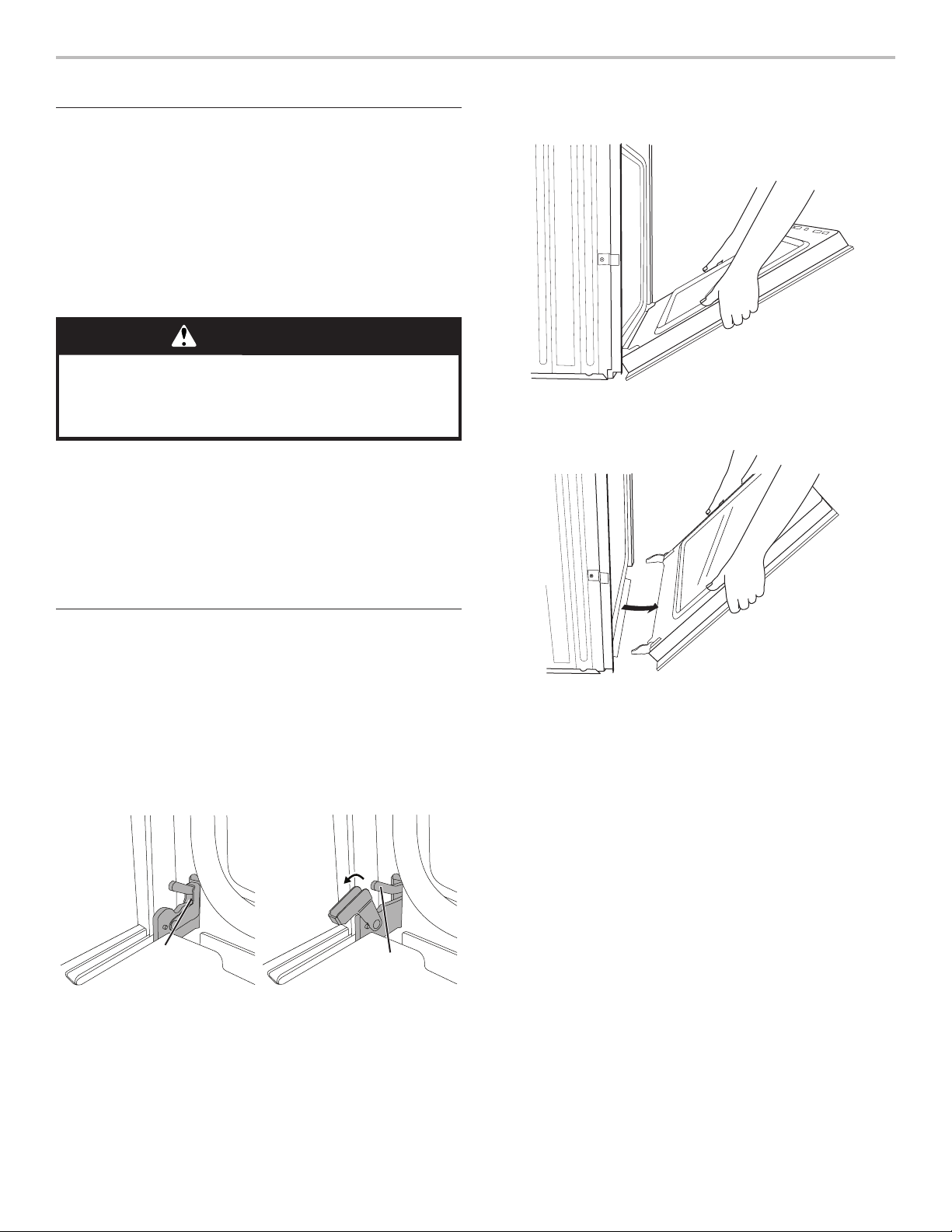
4. Partially close the door to engage the door latch locks. The
door will stop at this point.
5. Using two hands, grasp the edges of the oven door. Lift and
pull the oven door toward you, and remove. You may need to
gently shift door from side to side as you pull.
Remove Oven Door(s)
IMPORTANT: Use two hands to remove oven door(s).
1. Prior to removing the oven door, prepare a surface where
you will place it. This surface should be at and covered with
a soft blanket, or use the corner posts from your packaging
material.
2. Open the oven door.
3. Locate the oven door hinge locks in both corners of the oven
door, and rotate the hinge locks toward the oven door to the
unlocked position. If the door hinge lock is not rotated fully
(see illustration B), the door will not remove properly.
position
Grip here
to rotate.
A Oven door hinge lock
in locked position
Unlocked
position
Soft close hinge
arm on select models
B. Oven door hinge lock in
partially unlocked position
6. Set the oven door(s) aside on the prepared covered work
surface with the oven door resting on its handle.
7. To continue with the oven installation, go to the “Positioning
Oven Feet” section.
5
Page 6
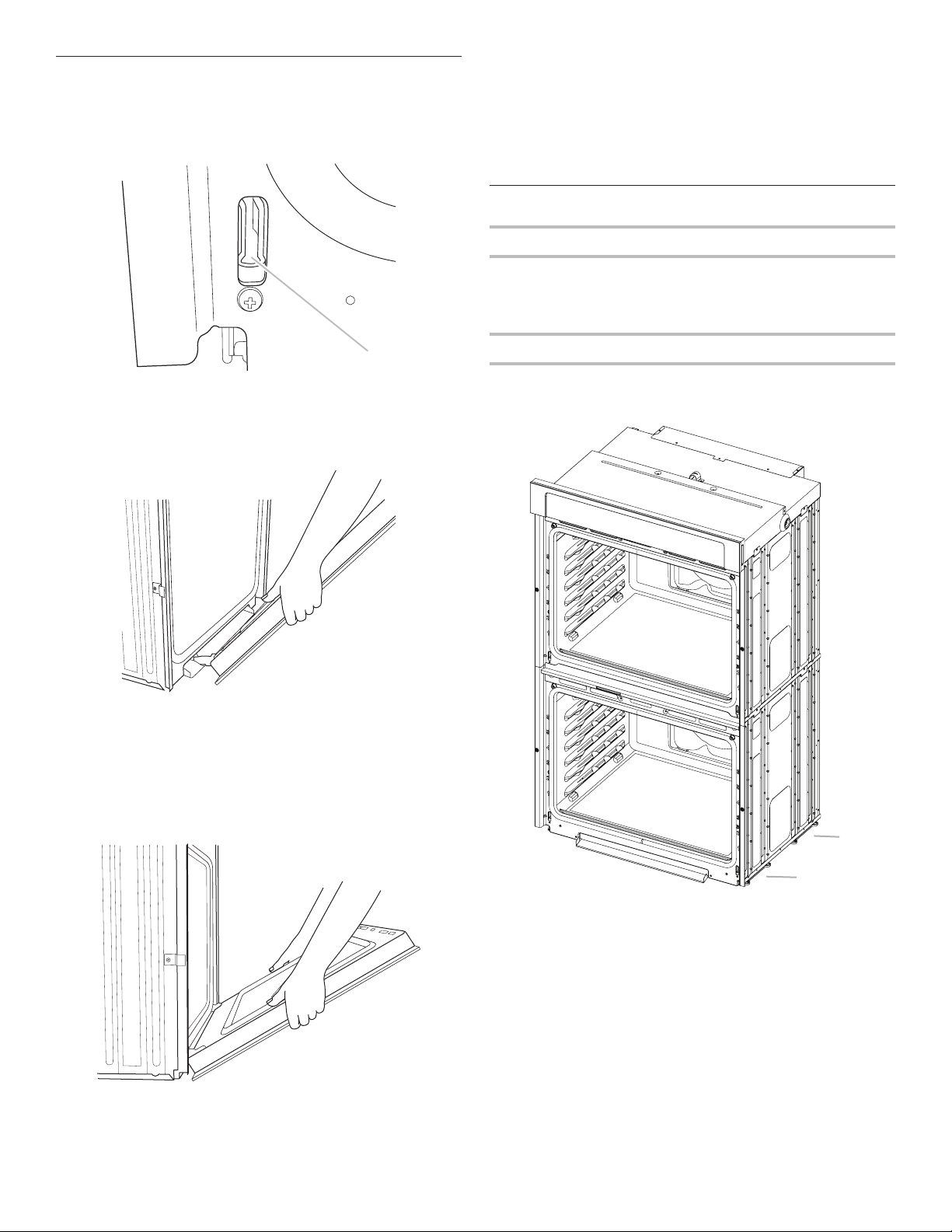
Replace Oven Door(s)
A
A
1. Using two hands, grasp side edges of door at the midpoint.
Face the oven cavity.
2. Locate the slots on each side of the oven cavity for the door
hinge locks.
6. Close the oven door.
7. When the hinges are properly installed and the door closed,
there should be an even gap between the door and the
control panel. If one side of the oven door is hanging lower
than the other, the hinge on that side is not properly installed.
Repeat the steps to remove, then replace the oven door. See
the “Remove Oven Door(s)” and “Replace Oven Door(s).”
sections.
Positioning Oven Feet
Single Ovens
The positioning of the oven feet allows a single oven to be
installed in a recommended cutout height of 281/2" (72.4 cm).
Go to the “Make Electrical Connection” section in the Installation
Instructions provided with your built-in oven.
A
A. Slot in the oven cavity for door hinge lock
3. At a 45° angle, align door hinges with slots in the lower
frontof the oven cavity. Slowly insert door, making sure you
maintain the 45° angle. You will know the door is engaged
inthe slot when you feel a slight drop.
4. Lower the oven door to the fully open position. If the oven
door does not open to a full 90 degrees, repeat steps 1
through 3.
5. Locate the oven door hinge locks in the corners of the oven
door, and rotate the hinge locks toward the oven cavity to
the locked position.
See Step 3 (illustration A) in the “Remove Oven Door(s)”
section for proper locked position.
Double Ovens
The oven feet need to be installed to allow a double oven to be
installed in a recommended cutout height of 517/16" (130.6 cm).
NOTE: Do not remove the spacers.
A. Spacers
6
Page 7
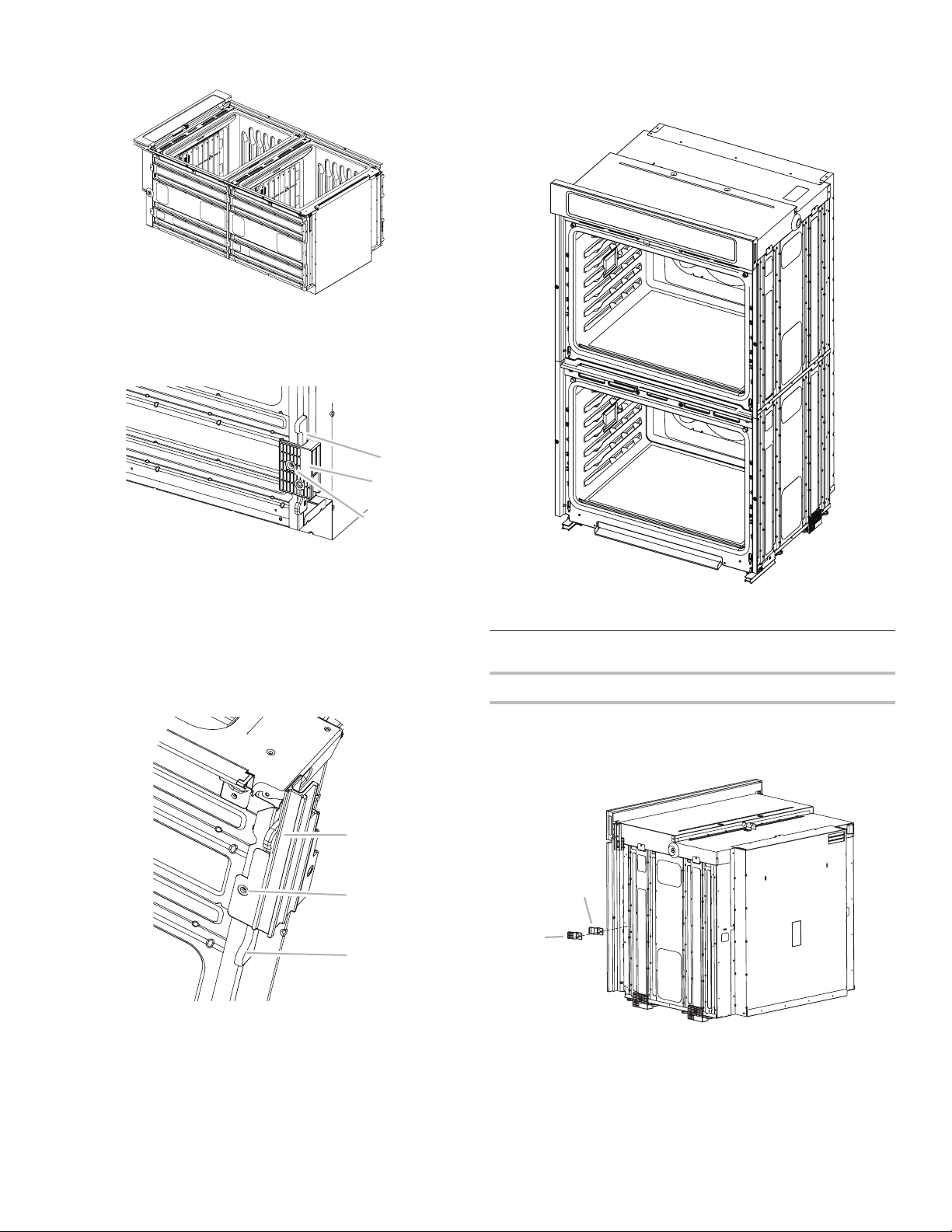
1. Using 2 or more people, place the oven on its back on a
A
A
B
covered surface.
2. Install a foot on the left rear spacer using a #8-18 x 3/8"
screw.
NOTE: Position the foot so the long side of the foot is
facingtoward the top of the oven.
B
5. In the same manner, install a front foot on the right front of
the oven.
6. Using 2 or more people, place the oven in its upright
position.
C
A. Spacer
B. Foot
C. #8-18 x
3
/8" screw
3. In the same manner, install a foot on the right rear of
theoven.
4. Install a front foot on the left front spacer using a
#8-18x3/8"screw.
NOTE: Position the foot so the long side of the foot is
facingtoward the inside of the oven.
B
C
7. Go to the “Make Electrical Connection” section in the
Installation Instructions provided with your built-in oven.
Replace Plastic Spacers
Replace Plastic Spacers on Single Ovens
1. Remove the screw attaching the plastic spacer (A) to the
right side of the oven.
2. Using the screw removed, install a new plastic spacer (B)
provided with this kit.
A
A. Front foot
B. #8-18 x
C. Spacer
3
/8" screw
A. Plastic spacer
B. New plastic spacer
7
Page 8
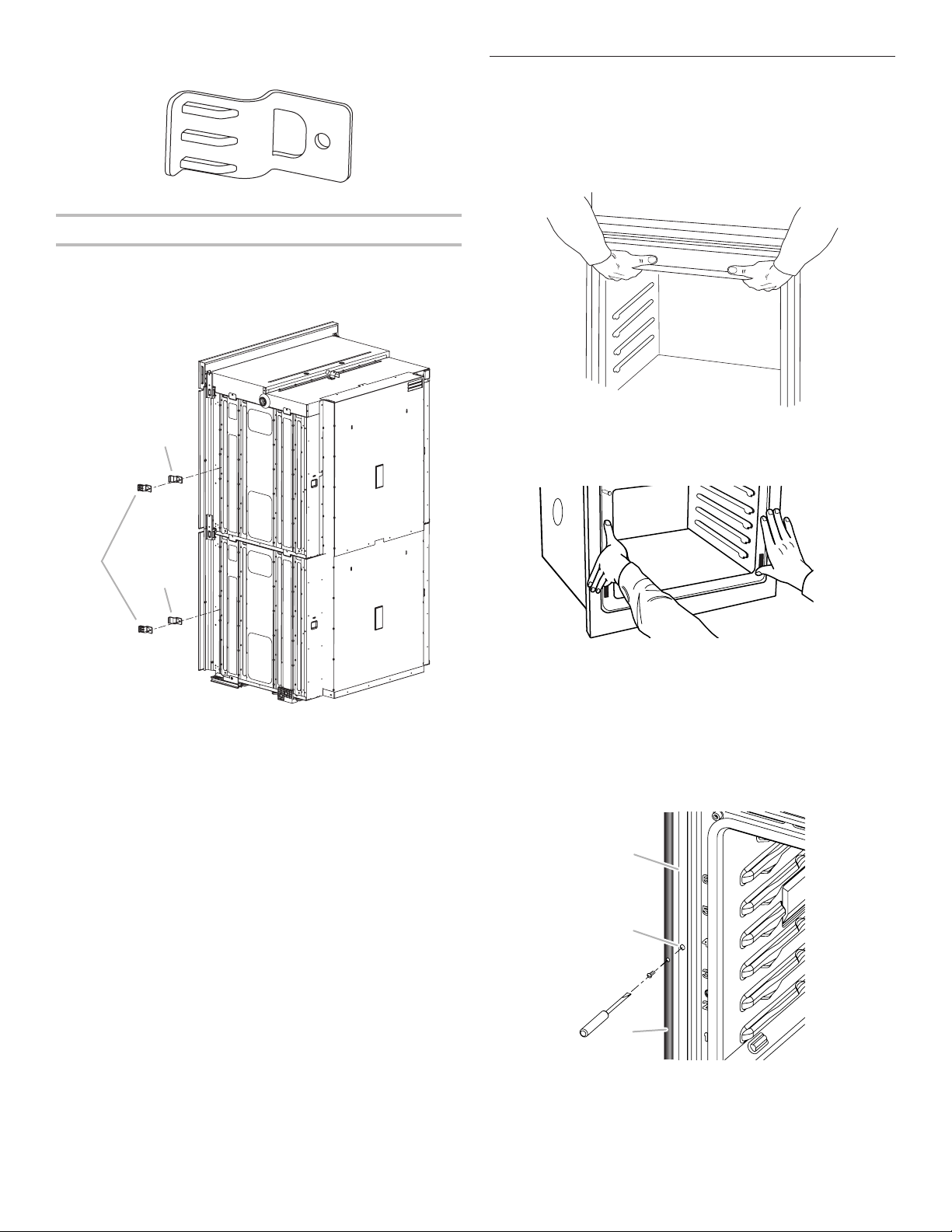
3. In the same manner, remove and replace the plastic spacer
B
on the left side of the oven.
New plastic spacer
Replace Plastic Spacers on Double Ovens
1. Remove the 2 screws, 1 in each spacer, attaching the 2
plastic spacers (A) to the right side of the oven.
2. Using the 2 screws removed, install 2 new plastic spacers
(B)provided with this kit.
Install Oven
1. Using 2 or more people, lift the oven partially into the cabinet
cutout. Use the oven opening as an area to grip.
NOTE: When pushing the microwave oven into the cabinet,
open the microwave oven door and push against the seal
area on the front frame. Do not push against the outside
edges.
A
A
A. Plastic spacer
B. New plastic spacer
3. In the same manner, remove and replace the 2 plastic
spacers on the left side of the oven.
2. Push against the front frame of the microwave oven to push
oven into cabinet. Push microwave oven completely into
cabinet and center in cabinet cutout.
3. Push the oven completely into the cabinet, and center the
oven into the cabinet cutout.
4. Remove the tape from the black front trim piece.
■ Securely fasten the oven to the cabinet using the
#8-14x3/4" screws provided.
■ Insert the screws through the hole in the black trim piece,
aligning with the hole in the oven frame. Do not
overtighten the screws.
A
B
C
A. Oven frame
B. Oven frame hole
C. Black trim piece
8
Page 9
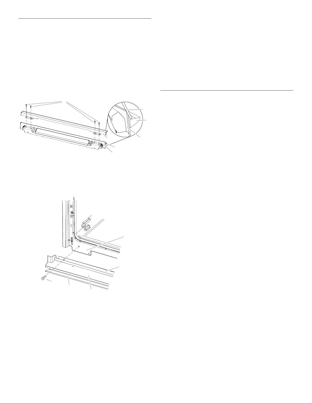
Install Deector Kit Bracket
D
A
C
A
C
This assembly is required for use when a single or double
built-in oven is installed in a ush installation.
1. Flex the upper vent piece (C) away from the lower vent
piece (D) to slide the deector bracket (B) between them.
Some force may be required to ex the upper vent trim (C)
away from the lower vent trim (D). Some force may also
be required to ex the deector bracket (B) and slide it
into position. Make sure screw holes are properly aligned
between the two pieces. See the following illustration.
2. Install the deector bracket (B) to the lower vent piece (D)
using two #8-18 x 1/4" screws on each side.
NOTE: On 27" (68.6 cm) models, only one #8-18 x 1/4"
screwis used on each side.
B
C
A. #8–18 x 1/4" screws
B. Deector bracket
C. Upper vent piece (supplied with oven)
D. Lower vent piece (supplied with oven)
3. Align vent tab (B) with oven frame (A) as shown in the
following illustration.
4. Using one #8-18 x 3/8" screw (E) on each side of the vent
tab(B), fasten the vent securely to the oven.
B
E
D
D
5. Replace the oven racks.
6. Replace the oven door. See the “Replace Oven Door(s)”
section.
7. Check that the door is free to open and close. If it is not,
repeat the removal and installation procedures. See the
“Prepare Built-In Oven” section.
8. Repeat for lower oven door.
9. Reconnect power.
10. The display panel will light.
11. If the display panel does not light, refer to the “Assistance
or Service” section of the Use and Care Guide provided
with your built-in oven or contact the dealer from whom
youpurchased your oven.
Complete Installation
B
1. Check that all parts are now installed. If there is an extra
part, go back through the steps to see which step was
skipped.
2. Check that you have all of your tools.
3. Dispose of/recycle all packaging materials.
4. For oven use and cleaning, read the Use and Care Guide.
Check Operation of Single and Double Ovens
1. At rst use, set up the language, clock, and any other
preferences if available. For more information, read the Use
and Care Guide.
2. Press OVEN on single oven models.
NOTE: Press UPPER or LOWER on double oven models.
3. Select Cooking Methods.
4. Select Broil.
5. Set the temperature.
6. Select Start.
If oven(s) does not operate, check the following:
■ Household fuse is intact and tight, or circuit breaker
has not tripped.
■ Electrical supply is connected.
■ See the “Troubleshooting” section in the Use and
CareGuide.
7. When oven has been on for 5 minutes, feel for heat.
If you do not feel heat or if an error message appears in the
display, turn off the oven and contact a qualied technician.
8. Press UPPER or LOWER on double ovens, or press OVEN
on single ovens, to cancel.
If you need Assistance or Service:
Please reference the “Warranty” section of the Use and Care
Guide.
A. Oven frame
B. Vent tab
C. Oven vent
D. Deector bracket
E. #8–18 x
3
/8" screw
9
Page 10

W11115048A
©2017. Used under license in Canada. All rights reserved.
Utilisé sous licence au Canada. Tous droits réservés.
09/17
 Loading...