

Whirlpool WMH32519HS, AMV6507RGS Dimension Guide
MICROWAVE HOOD COMBINATION
A B
(43.5 cm)
(41.3 cm)
INSTALLATION INSTRUCTIONS
PRODUCT MODEL NUMBERS
WMH32519H
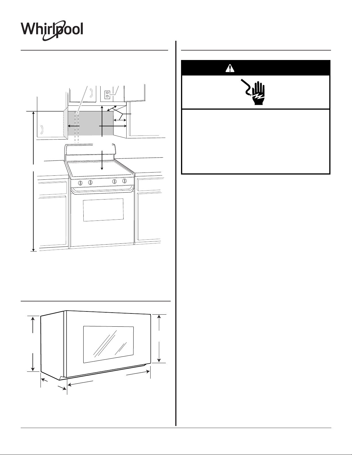
Installation Dimensions
NOTE: The grounded 3 prong outlet must be inside the upper cabinet.
See the “Electrical Requirements” section.
ELECTRICAL REQUIREMENTS
WARNING
12" (30.5 cm) min.
14" (35.6 cm) max.
upper cabinet and
side cabinet depth
66" (167.6 cm) min.
30"
(76.2 cm)
min.
30"
(76.2 cm)
typical*
A. 2" x 4" (5.08 x 10.16) wall stud
B. Grounded 3 prong outlet
*30" (76.2 cm) is typical for 66” (167.6 cm) installation height. Exact
dimensions may vary depending on type of range/
cooktop below.
Electrical Shock Hazard
Plug into a grounded 3 prong outlet.
Do not remove ground prong.
Do not use an adapter.
Do not use an extension cord.
Failure to follow these instructions can result in death,
fire, or electrical shock.
Observe all governing codes and ordinances.
Required:
■ A 120-volt, 60 Hz, AC-only, 15- or 20-amp electrical supply with a fuse
or circuit breaker
Recommended:
■ A time-delay fuse or time-delay circuit breaker
■ A separate circuit serving only this microwave oven
PRODUCT DIMENSIONS
"
¹⁄₈
17
"
³⁄₁₆
+/(0.5 cm)
Up to
16
(42.5 cm)*
³⁄₄
"
*Overall depth of product will vary slightly depending on
door design.
Because Whirlpool Corporation includes a continuous commitment to improve our
products, we reserve the right to change materials and specifications without notice.
⁷⁄₈
29
" (76.0 cm)
"
¹⁄₄
16
Dimensions are for planning purposes only. For complete details, see Installation
Instructions packed with product. Specifications subject to change without notice.
Page 1 of 3
Ref. W11084412A
05/31/2017

VENTING DESIGN SPECIFICATIONS
A
B
C
E
D
A B C
D E F G
This section is intended for architectural designer and builder/ contractor
reference only.
NOTES:
■ Vent materials needed for installation are not provided with microwave
hood combination.
■ We do not recommend using a flexible metal vent.
■ To avoid possible product damage, be sure to vent air outside, unless
using recirculation installation. Do not vent exhaust air into concealed
spaces, such as spaces within walls or ceilings, attics, crawl spaces,
or garages.
For optimal venting installation, we recommend:
■ Using roof or wall caps that have backdraft dampers
■ Using a rigid metal vent
■ Using the most direct route by minimizing the length of the vent and
number of elbows to provide efficient performance
■ Using uniformly sized vents
■ Using duct tape to seal all joints in the vent system
■ Using caulking compound to seal exterior wall or roof opening around
cap
■ Not installing 2 elbows together for optimal hood performance
If venting through the wall, be sure that there is proper clearance within
the wall for the damper to open fully.
If venting through the roof, and rectangular-to-round transition
is used, be sure there are at least 3" (7.6 cm) of clearance
between the top of the microwave oven and the transition
piece. See “Rectangular-to-Round Transition” illustration.
Rectangular-to-Round Transition
NOTE: The minimum 3" (7.6 cm) clearance must exist between the top
of the microwave oven and the rectangular to round transition piece so
that the damper can open freely and fully.
3" (7.6 cm)
F
A. Roof cap
B. 6" (15.2 cm) min. diameter round vent
C. Elbow (for wall venting only)
D. Wall cap
E. 3¹⁄₄" x 10" to 6" (8.3 x 25.4 cm to 15.2 cm)
rectangular to round transition piece
F. Vent extension piece, at least 3" (7.6 cm) high
Recommended Standard Fittings
The following length equivalents are for use when figuring vent length.
See the examples in “Recommended Vent Length.”
Roof venting Roof cap
Wall venting
Because Whirlpool Corporation includes a continuous commitment to improve our
products, we reserve the right to change materials and specifications without notice.
A. Rectangular-to-round transition piece: 3¹⁄₄" x 10" to 6" = 5 ft
(8.3 x 25.4 cm to 15.2 cm = 1.5 m)
B. Roof cap: 3¹⁄₄" x 10" = 24 ft (8.3 x 25.4 cm = 7.3 m)
C. 90° elbow: 3¹⁄₄" x 10" = 25 ft (8.3 x 25.4 cm = 7.6 m)
D. 90° elbow: 6" = 10 ft (15.2 cm = 3 m)
Wall cap
E. Wall cap: 3¹⁄₄" x 10" = 40 ft (8.3 x 25.4 cm = 12.2 m)
F. 45° elbow: 6" = 5 ft (15.2 cm = 1.5 m)
G. 90° flat elbow: 3¹⁄₄" x 10" = 10 ft (8.3 x 25.4 cm = 3 m)
Dimensions are for planning purposes only. For complete details, see Installation
Instructions packed with product. Specifications subject to change without notice.
Page 2 of 3
Ref. W11084412A
05/31/2017
 Loading...