

Whirlpool WMB, WMB36VB-1A, WMB48VB-1A, WMB60VB-1A, WMB24 Installation Instructions
...
AIR HANDLER INSTALLATION INSTRUCTIONS
Table of Contents
AIR HANDLER SAFETY .................................................................1
INSTALLATION REQUIREMENTS................................................1
Tools and Parts ............................................................................2
Location Requirements................................................................ 2
Installation Configurations ...........................................................3
Electrical Requirements ...............................................................3
Ductwork Requirements ..............................................................4
INSTALLATION INSTRUCTIONS..................................................4
Inspect Shipment.........................................................................4
AIR HANDLER SAFETY
Your safety and the safety of others are very important.
We have provided many important safety messages in this manual and on your appliance. Always read and obey all safety
messages.
This is the safety alert symbol.
This symbol alerts you to potential hazards that can kill or hurt you and others.
All safety messages will follow the safety alert symbol and either the word “DANGER” or “WARNING.”
These words mean:
Install Ductwork............................................................................4
Install Filter....................................................................................4
Make Electrical Connections .......................................................5
Complete Installation....................................................................7
SEQUENCE OF OPERATION ......................................................10
AIR HANDLER MAINTENANCE ..................................................10
ASSISTANCE OR SERVICE.........................................................10
Accessories ................................................................................10
WARRANTY ..................................................................................11
You can be killed or seriously injured if you don't immediately
DANGER
WARNING
All safety messages will tell you what the potential hazard is, tell you how to reduce the chance of injury, and tell you what can
happen if the instructions are not followed.
follow instructions.
can be killed or seriously injured if you don't
You
instructions.
INSTALLATION REQUIREMENTS
These instructions are intended as a general guide only and do
not supersede any national or local codes in any way.
Compliance with all local, state, or national codes pertaining to
this type of equipment should be determined prior to installation.
Read this entire instruction manual, as well as the instructions
supplied in separate equipment, before starting the installation.
All models are designed for indoor installation only.
Whirlpool© Model WMB
0650329-60
The installation of the air handler, field wiring, warm air ducts, etc.
must conform to the requirements of the National Electrical
Code, ANSI/NFPA No. 70 (latest edition) in the United States, and
any state laws, and local ordinances (including plumbing or
wastewater codes). Local authorities having jurisdiction should
be consulted before installation is made. Such applicable
regulations or requirements take precedence over the general
instructions in this manual.
follow
Install the conditioned air plenum, ducts and air filters (not
provided) in accordance with NFPA 90B Standard for the
Installation of Warm Air Heating and Air-Conditioning Systems
(latest edition).
The air handler is provided with flanges for the connection of the
plenum and ducts.
Air filters (not provided) must be listed as Class 2 furnace air
filters.
The air handler may be used with an optional modular evaporator
coil (WEM) in upflow, counterflow, or horizontal applications. See
“Installation Configuration Options” in “Installation
Configurations” for acceptable system configurations. The
mounting plates and the necessary hardware to connect the air
handler and modular evaporator coil cabinets together are
included with this air handler.
An optional electric heater may be installed in this cabinet. For
electric heater accessory, refer to the electric heater rating plate
for specific information regarding the electric supply.
Do not remove the cabinet knockouts until it has been
determined which knockouts will need to be removed for the
installation.
Select any accessories that are to be included in this installation.
Select the final installation position which best suits the site
conditions. Consider required clearances, space, routing
requirements for refrigerant line, condensate disposal, filters,
ductwork, wiring, and accessibility for service. Refer to the air
handler rating plate on the air handler for specific information.
Tools and Parts
Gather the required tools and parts before starting installation.
Read and follow the instructions provided with any tools listed
here.
Tools Needed
■ ¹⁄₄" nut driver
■ Level
■ Screwdriver
■ Adjustable wrench
Parts Needed
Check local codes, check existing electrical supply, and read
“Ductwork Requirements,” and “Electrical Requirements,” before
purchasing parts.
■ UL listed wire nuts
Parts Supplied
The mounting plates and the necessary hardware to connect the
air handler and modular evaporator coil cabinets together are
included with the air handler.
■ Tape measure
■ Hammer
■ Sealant
Location Requirements
WARNING
Explosion Hazard
Keep flammable materials and vapors, such as
gasoline, away from air handler.
Place air handler so that heating elements are at least
18 inches (46 cm) above the floor for a garage
installation.
Failure to follow these instructions can result in death,
explosion, or fire.
NOTE: When used on cooling applications, excessive sweating
may occur when the air handler with optional evaporator coil
(WEM) is installed in a very humid space.
■ If installed in an unconditioned space, sealant should be
applied around the electrical wires, refrigerant tubing, and
condensate lines where they enter the cabinet.
■ Electrical wires should be sealed on the inside where they exit
the conduit opening. Sealant is required to prevent air
leakage into and condensate from forming inside the air
handler, control box, and on electrical controls.
■ The air handler must be installed in such a way as to allow
free access to the optional coil/filter compartment and
blower/control compartment.
Installation Clearances
Non-Ducted Return Closet Installation
The air handler can be installed in a closet with a false bottom to
form a return air plenum, with a return air plenum through the wall
of the closet, with an air duct routed through the floor, or with
another approved method. Louvered closet doors or return air
grilles are field supplied. Local codes may limit application of
systems without a ducted return to single-story buildings.
■ Louvered closet doors shall be sized with the minimum
opening required to provide minimum return air free area. See
Minimum Filter Requirements Chart.
■ Louvers installed in a closet to provide return air shall be
sized with minimum opening required to provide minimum air
return free area. See Minimum Filter Requirements Chart.
■ Return air plenum installed through the floor shall be sized
with minimum opening required to provide minimum return
free area. See Minimum Filter Requirements Chart.
■ If the free area is not known, assume a 25% free area for
wood or a 75% free area for metal louvers or grilles.
■ If the return air plenum is used, the return air grille should be
immediately in front of the opening in the plenum to allow for
the free flow of return air.
■ When not installed in front of the opening, there must be
adequate clearance around the air handler to allow for the
free flow of return air.
2
Installation Configurations
For ease in installation, it is best to make any necessary coil
configuration changes before setting the air handler in place. See
“Installation Configuration Options” later in this section.
Installation Configuration Options
NOTE: Typical installations with optional WEM modular
evaporator coil are shown.
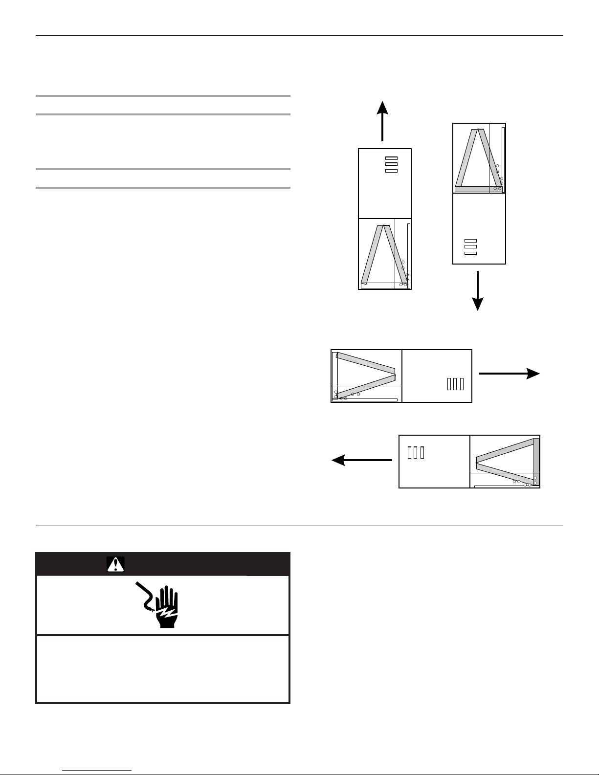
Vertical Installations
Upflow/Counterflow
The air handler must be supported on the bottom only and set on
a field-supplied supporting frame with an air return opening.
Securely attach the air handler to the supporting frame.
Horizontal Installations
Horizontal installations can be left-hand or right-hand air supply.
The cabinet must be supported by the building structure to
ensure cabinet integrity. Ensure that there is adequate room to
remove the blower access panel if installing in the horizontal
position.
Suspended Cabinet Installation
NOTE: Air handlers cannot be installed in such a way that the
blower access panel is facing up or down.
■ The suspending means must be field fabricated, and should
consist of two “cradles” made by attaching two rods to a
length of angle iron or equivalent structural steel.
■ Locate the cradles so that they are as close as possible to the
ends of the air handler (this will provide access for removal of
major components such as the blower assembly).
■ Provide enough clearance between the suspension rods and
the air handler to allow removal of the blower access panel.
Counterflow
Upflow
Electrical Requirements
WARNING
Electrical Shock Hazard
Electrically ground air handler.
Connect ground wire to ground terminal marked “GND”.
Failure to do so can result in death or electrical shock.
NOTES:
■ Use copper conductors only.
Left to Right
Airflow
Right to Left
Airflow
Horizontal
■ All field wiring must be done in accordance with National
Electrical Code, applicable requirements of UL and local
codes where applicable.
■ Electrical wiring, disconnect means and over-current
protection are to be supplied by the installer. Refer to the air
handler rating plate for maximum overcurrent protection,
minimum circuit ampacity, as well as operating voltage.
■ The power supply must be sized and protected according to
the specifications supplied on the product.
■ This air handler is factory-configured for 240 Volt, single
phase, 60 cycles. For 208 Volt applications, see “208 Volt
Conversion” in the “Make Electrical Connections” section.
■ For optional electric heater applications, see “Accessories.”
Refer to the instructions provided with the accessory for
proper installation.
3
Ductwork Requirements
■ Install the conditioned air plenum, ducts and air filters (not
provided) in accordance with NFPA 90B Standard for the
Installation of Warm Air Heating and Air-Conditioning
Systems (latest edition).
■ The air handler is provided with flanges for the connection of
the plenum and ducts.
■ All air filters (not provided) must be listed as Class 2 furnace
air filters.
INSTALLATION INSTRUCTIONS
■ Supply and return ductwork must be adequately sized to
meet the system’s air requirements and static pressure
capabilities. Ductwork should be insulated with a minimum of
1" thick insulation with a vapor barrier in conditioned areas or
2" minimum in unconditioned areas.
■ Supply plenum should be the same size as the flanged
opening provided around the blower outlet and should
extend ideally at least 3 ft from the air handler before turning
or branching off plenum into duct runs. The plenum forms an
extension of the blower housing and minimizes air expansion
losses from the blower.
Inspect Shipment
WARNING
Excessive Weight Hazard
Use two or more people to move and install air handler.
Failure to do so can result in back or other injury.
The air handler is completely factory assembled, and all
components are performance tested. Each unit consists of a
blower assembly and controls in an insulated, galvanized factoryfinished enclosure. Knockouts are provided for electrical wiring
entrance.
■ Check the unit rating plate to confirm specifications are as
ordered.
■ Upon receipt of equipment, inspect it for possible shipping
damage. Be sure to examine the unit inside the carton if the
carton is damaged.
■ If damage is found, it should be noted on the carrier’s freight
bill. Damage claims should be filed with the carrier
immediately. Claims of shortages should be filed with the
seller within 5 days.
NOTE: If any damages are discovered and reported to the carrier,
do not install the unit as your claim may be denied.
Install Ductwork
IMPORTANT:
■ Install ductwork in accordance with NFPA 90B Standard for
the Installation of Warm Air eating and Air-Conditioning
Sytems (latest edition) and any local codes.
■ Connect supply air duct to the flange on top of the unit. If an
isolation connector is used, it must be non-flammable.
■ A return air duct system is recommended. If the unit is
installed in a confined space or closet, the entire duct cross
sectional area must meet minimum return air free area.
Install Filter
Filters are not supplied with these air handlers. It is the installer's
responsibility to install properly sized filters in accordance with
the Minimum Filter Requirements Chart.
■ The filter size is determined by the “Nominal Tons Air
Conditioning & Nominal Airflow” (see chart).
■ Areas and dimensions shown for cleanable filters are based
on filters rated at 600 ft per minute face velocity.
■ Typical filter sizes are shown; however, any combination of
filters whose area equals or exceeds the minimum area
shown is satisfactory.
Minimum Filter Requirements Chart
Nominal Tons
Air Conditioning
& Nominal
Airflow
Up to 2 Tons
800 - 900 CFM
2¹⁄₂ To n s
900-1000 CFM
3 Tons
1100 - 1300 CFM
3¹⁄₂ To n s
1300 - 1500 CFM
4 Tons
1500 - 1700 CFM
5 Tons
1900 - 2100 CFM
* 2 disposable filters required for these units
If a central return air filter-grille is used, the air handler does not
require a filter.
Square Inch Surface Area
&Nominal Size
Disposable
Filters
432 sq. in.
20" x 25"
480 sq. in.
20" x 30"
576 sq. in.
*14" x 25"
672 sq. in.
*16" x 25"
768 sq. in.
*20" x 25"
960 sq. in.
*20" x 30"
Cleanable
Filters
260 sq. in.
15" x 20"
288 sq. in.
14" x 25"
346 sq. in.
16" x 25"
404 sq. in.
20" x 25"
461 sq. in.
20" x 25"
576 sq. in.
24" x 25"
Minimum
Return Air
Free Area
260 sq. in.
288 sq. in.
346 sq. in.
404 sq. in.
461 sq. in.
576 sq. in.
4
 Loading...