

Page 1
AIR HANDLER INSTALLATION INSTRUCTIONS
Table of Contents
AIR HANDLER SAFETY .................................................................1
INSTALLATION REQUIREMENTS................................................1
Tools and Parts ............................................................................2
Location Requirements................................................................ 2
Installation Configurations ...........................................................3
Electrical Requirements ...............................................................3
Ductwork Requirements ..............................................................4
INSTALLATION INSTRUCTIONS..................................................4
Inspect Shipment.........................................................................4
AIR HANDLER SAFETY
Your safety and the safety of others are very important.
We have provided many important safety messages in this manual and on your appliance. Always read and obey all safety
messages.
This is the safety alert symbol.
This symbol alerts you to potential hazards that can kill or hurt you and others.
All safety messages will follow the safety alert symbol and either the word “DANGER” or “WARNING.”
These words mean:
Install Ductwork............................................................................4
Install Filter....................................................................................4
Make Electrical Connections .......................................................5
Complete Installation....................................................................7
SEQUENCE OF OPERATION ......................................................10
AIR HANDLER MAINTENANCE ..................................................10
ASSISTANCE OR SERVICE.........................................................10
Accessories ................................................................................10
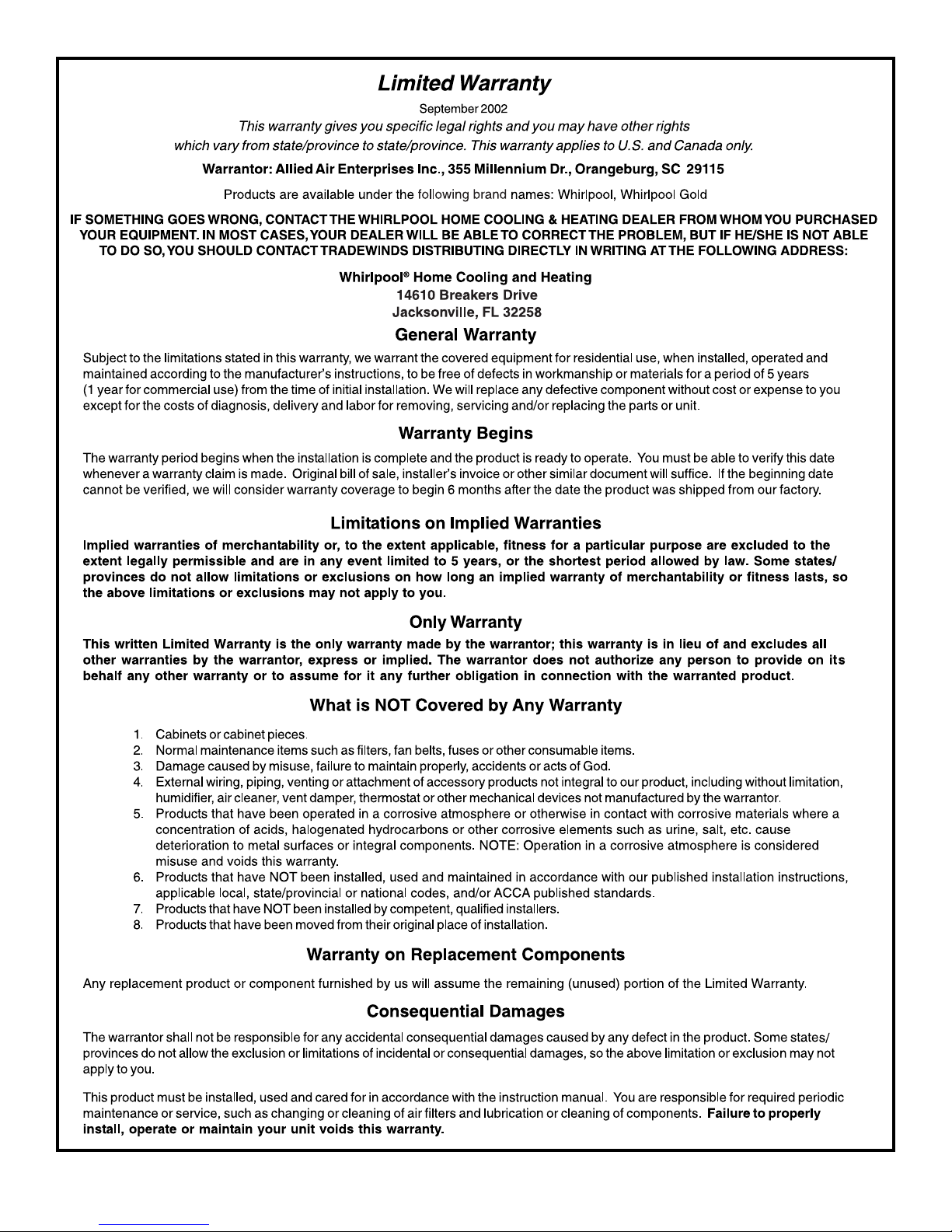
WARRANTY ..................................................................................11
You can be killed or seriously injured if you don't immediately
DANGER
WARNING
All safety messages will tell you what the potential hazard is, tell you how to reduce the chance of injury, and tell you what can
happen if the instructions are not followed.
follow instructions.
can be killed or seriously injured if you don't
You
instructions.
INSTALLATION REQUIREMENTS
These instructions are intended as a general guide only and do
not supersede any national or local codes in any way.
Compliance with all local, state, or national codes pertaining to
this type of equipment should be determined prior to installation.
Read this entire instruction manual, as well as the instructions
supplied in separate equipment, before starting the installation.
All models are designed for indoor installation only.
Whirlpool© Model WMB
0650329-60
The installation of the air handler, field wiring, warm air ducts, etc.
must conform to the requirements of the National Electrical
Code, ANSI/NFPA No. 70 (latest edition) in the United States, and
any state laws, and local ordinances (including plumbing or
wastewater codes). Local authorities having jurisdiction should
be consulted before installation is made. Such applicable
regulations or requirements take precedence over the general
instructions in this manual.
follow
Page 2
Install the conditioned air plenum, ducts and air filters (not
provided) in accordance with NFPA 90B Standard for the
Installation of Warm Air Heating and Air-Conditioning Systems
(latest edition).
The air handler is provided with flanges for the connection of the
plenum and ducts.
Air filters (not provided) must be listed as Class 2 furnace air
filters.
The air handler may be used with an optional modular evaporator
coil (WEM) in upflow, counterflow, or horizontal applications. See
“Installation Configuration Options” in “Installation
Configurations” for acceptable system configurations. The
mounting plates and the necessary hardware to connect the air
handler and modular evaporator coil cabinets together are
included with this air handler.
An optional electric heater may be installed in this cabinet. For
electric heater accessory, refer to the electric heater rating plate
for specific information regarding the electric supply.
Do not remove the cabinet knockouts until it has been
determined which knockouts will need to be removed for the
installation.
Select any accessories that are to be included in this installation.
Select the final installation position which best suits the site
conditions. Consider required clearances, space, routing
requirements for refrigerant line, condensate disposal, filters,
ductwork, wiring, and accessibility for service. Refer to the air
handler rating plate on the air handler for specific information.
Tools and Parts
Gather the required tools and parts before starting installation.
Read and follow the instructions provided with any tools listed
here.
Tools Needed
■ ¹⁄₄" nut driver
■ Level
■ Screwdriver
■ Adjustable wrench
Parts Needed
Check local codes, check existing electrical supply, and read
“Ductwork Requirements,” and “Electrical Requirements,” before
purchasing parts.
■ UL listed wire nuts
Parts Supplied
The mounting plates and the necessary hardware to connect the
air handler and modular evaporator coil cabinets together are
included with the air handler.
■ Tape measure
■ Hammer
■ Sealant
Location Requirements
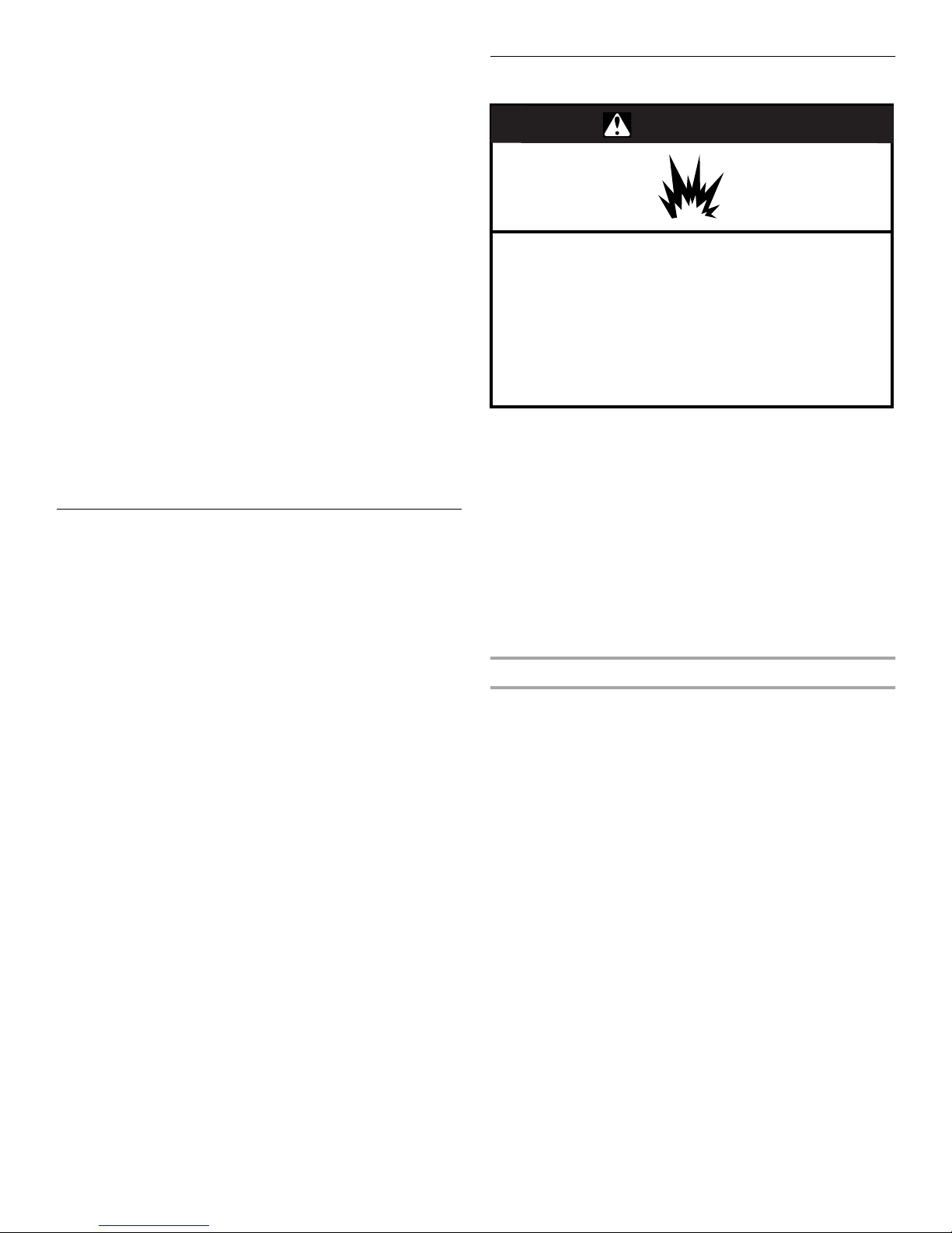
WARNING
Explosion Hazard
Keep flammable materials and vapors, such as
gasoline, away from air handler.
Place air handler so that heating elements are at least
18 inches (46 cm) above the floor for a garage
installation.
Failure to follow these instructions can result in death,
explosion, or fire.
NOTE: When used on cooling applications, excessive sweating
may occur when the air handler with optional evaporator coil
(WEM) is installed in a very humid space.
■ If installed in an unconditioned space, sealant should be
applied around the electrical wires, refrigerant tubing, and
condensate lines where they enter the cabinet.
■ Electrical wires should be sealed on the inside where they exit
the conduit opening. Sealant is required to prevent air
leakage into and condensate from forming inside the air
handler, control box, and on electrical controls.
■ The air handler must be installed in such a way as to allow
free access to the optional coil/filter compartment and
blower/control compartment.
Installation Clearances
Non-Ducted Return Closet Installation
The air handler can be installed in a closet with a false bottom to
form a return air plenum, with a return air plenum through the wall
of the closet, with an air duct routed through the floor, or with
another approved method. Louvered closet doors or return air
grilles are field supplied. Local codes may limit application of
systems without a ducted return to single-story buildings.
■ Louvered closet doors shall be sized with the minimum
opening required to provide minimum return air free area. See
Minimum Filter Requirements Chart.
■ Louvers installed in a closet to provide return air shall be
sized with minimum opening required to provide minimum air
return free area. See Minimum Filter Requirements Chart.
■ Return air plenum installed through the floor shall be sized
with minimum opening required to provide minimum return
free area. See Minimum Filter Requirements Chart.
■ If the free area is not known, assume a 25% free area for
wood or a 75% free area for metal louvers or grilles.
■ If the return air plenum is used, the return air grille should be
immediately in front of the opening in the plenum to allow for
the free flow of return air.
■ When not installed in front of the opening, there must be
adequate clearance around the air handler to allow for the
free flow of return air.
2
Page 3
Installation Configurations
For ease in installation, it is best to make any necessary coil
configuration changes before setting the air handler in place. See
“Installation Configuration Options” later in this section.
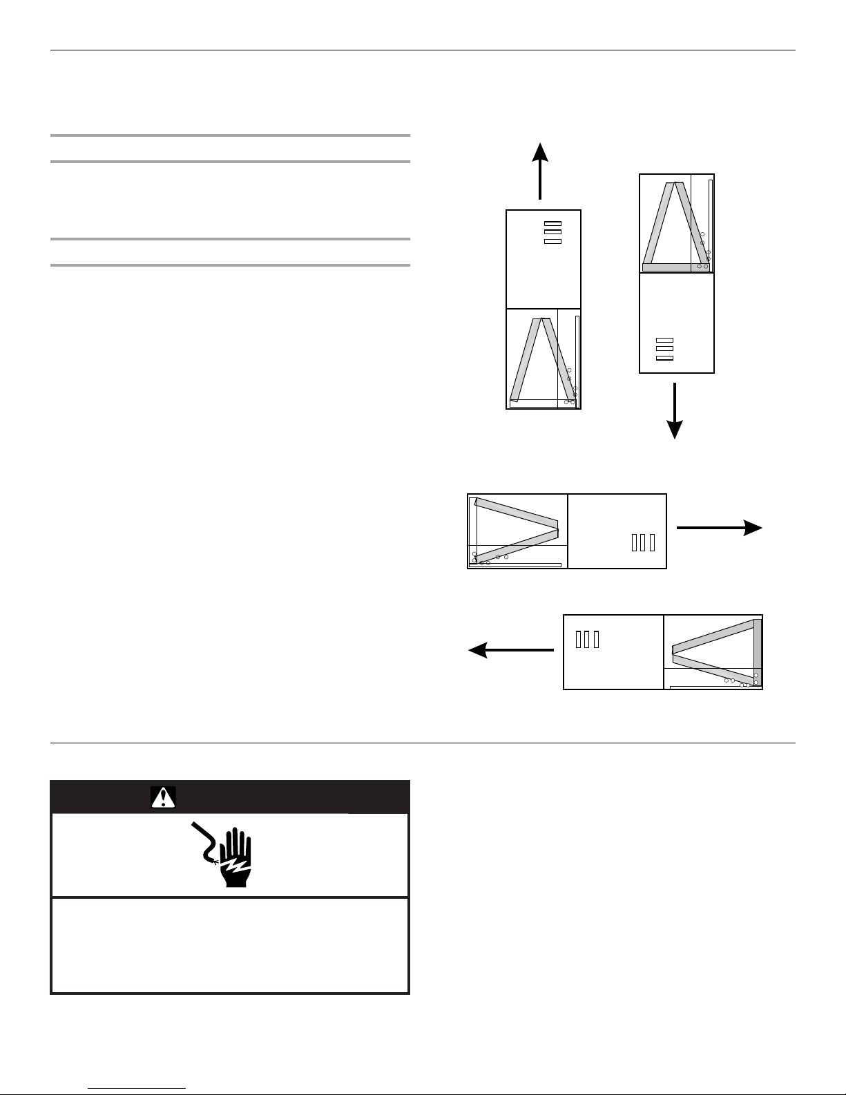
Installation Configuration Options
NOTE: Typical installations with optional WEM modular
evaporator coil are shown.
Vertical Installations
Upflow/Counterflow
The air handler must be supported on the bottom only and set on
a field-supplied supporting frame with an air return opening.
Securely attach the air handler to the supporting frame.
Horizontal Installations
Horizontal installations can be left-hand or right-hand air supply.
The cabinet must be supported by the building structure to
ensure cabinet integrity. Ensure that there is adequate room to
remove the blower access panel if installing in the horizontal
position.
Suspended Cabinet Installation
NOTE: Air handlers cannot be installed in such a way that the
blower access panel is facing up or down.
■ The suspending means must be field fabricated, and should
consist of two “cradles” made by attaching two rods to a
length of angle iron or equivalent structural steel.
■ Locate the cradles so that they are as close as possible to the
ends of the air handler (this will provide access for removal of
major components such as the blower assembly).
■ Provide enough clearance between the suspension rods and
the air handler to allow removal of the blower access panel.
Counterflow
Upflow
Electrical Requirements
WARNING
Electrical Shock Hazard
Electrically ground air handler.
Connect ground wire to ground terminal marked “GND”.
Failure to do so can result in death or electrical shock.
NOTES:
■ Use copper conductors only.
Left to Right
Airflow
Right to Left
Airflow
Horizontal
■ All field wiring must be done in accordance with National
Electrical Code, applicable requirements of UL and local
codes where applicable.
■ Electrical wiring, disconnect means and over-current
protection are to be supplied by the installer. Refer to the air
handler rating plate for maximum overcurrent protection,
minimum circuit ampacity, as well as operating voltage.
■ The power supply must be sized and protected according to
the specifications supplied on the product.
■ This air handler is factory-configured for 240 Volt, single
phase, 60 cycles. For 208 Volt applications, see “208 Volt
Conversion” in the “Make Electrical Connections” section.
■ For optional electric heater applications, see “Accessories.”
Refer to the instructions provided with the accessory for
proper installation.
3
Page 4
Ductwork Requirements
■ Install the conditioned air plenum, ducts and air filters (not
provided) in accordance with NFPA 90B Standard for the
Installation of Warm Air Heating and Air-Conditioning
Systems (latest edition).
■ The air handler is provided with flanges for the connection of
the plenum and ducts.
■ All air filters (not provided) must be listed as Class 2 furnace
air filters.
INSTALLATION INSTRUCTIONS
■ Supply and return ductwork must be adequately sized to
meet the system’s air requirements and static pressure
capabilities. Ductwork should be insulated with a minimum of
1" thick insulation with a vapor barrier in conditioned areas or
2" minimum in unconditioned areas.
■ Supply plenum should be the same size as the flanged
opening provided around the blower outlet and should
extend ideally at least 3 ft from the air handler before turning
or branching off plenum into duct runs. The plenum forms an
extension of the blower housing and minimizes air expansion
losses from the blower.
Inspect Shipment
WARNING
Excessive Weight Hazard
Use two or more people to move and install air handler.
Failure to do so can result in back or other injury.
The air handler is completely factory assembled, and all
components are performance tested. Each unit consists of a
blower assembly and controls in an insulated, galvanized factoryfinished enclosure. Knockouts are provided for electrical wiring
entrance.
■ Check the unit rating plate to confirm specifications are as
ordered.
■ Upon receipt of equipment, inspect it for possible shipping
damage. Be sure to examine the unit inside the carton if the
carton is damaged.
■ If damage is found, it should be noted on the carrier’s freight
bill. Damage claims should be filed with the carrier
immediately. Claims of shortages should be filed with the
seller within 5 days.
NOTE: If any damages are discovered and reported to the carrier,
do not install the unit as your claim may be denied.
Install Ductwork
IMPORTANT:
■ Install ductwork in accordance with NFPA 90B Standard for
the Installation of Warm Air eating and Air-Conditioning
Sytems (latest edition) and any local codes.
■ Connect supply air duct to the flange on top of the unit. If an
isolation connector is used, it must be non-flammable.
■ A return air duct system is recommended. If the unit is
installed in a confined space or closet, the entire duct cross
sectional area must meet minimum return air free area.
Install Filter
Filters are not supplied with these air handlers. It is the installer's
responsibility to install properly sized filters in accordance with
the Minimum Filter Requirements Chart.
■ The filter size is determined by the “Nominal Tons Air
Conditioning & Nominal Airflow” (see chart).
■ Areas and dimensions shown for cleanable filters are based
on filters rated at 600 ft per minute face velocity.
■ Typical filter sizes are shown; however, any combination of
filters whose area equals or exceeds the minimum area
shown is satisfactory.
Minimum Filter Requirements Chart
Nominal Tons
Air Conditioning
& Nominal
Airflow
Up to 2 Tons
800 - 900 CFM
2¹⁄₂ To n s
900-1000 CFM
3 Tons
1100 - 1300 CFM
3¹⁄₂ To n s
1300 - 1500 CFM
4 Tons
1500 - 1700 CFM
5 Tons
1900 - 2100 CFM
* 2 disposable filters required for these units
If a central return air filter-grille is used, the air handler does not
require a filter.
Square Inch Surface Area
&Nominal Size
Disposable
Filters
432 sq. in.
20" x 25"
480 sq. in.
20" x 30"
576 sq. in.
*14" x 25"
672 sq. in.
*16" x 25"
768 sq. in.
*20" x 25"
960 sq. in.
*20" x 30"
Cleanable
Filters
260 sq. in.
15" x 20"
288 sq. in.
14" x 25"
346 sq. in.
16" x 25"
404 sq. in.
20" x 25"
461 sq. in.
20" x 25"
576 sq. in.
24" x 25"
Minimum
Return Air
Free Area
260 sq. in.
288 sq. in.
346 sq. in.
404 sq. in.
461 sq. in.
576 sq. in.
4
Page 5
Make Electrical Connections
208/240 Volt Installations
WARNING
Electrical Shock Hazard
Disconnect all power supplies before servicing.
Replace all parts and panels before operating.
Failure to do so can result in death or electrical shock.
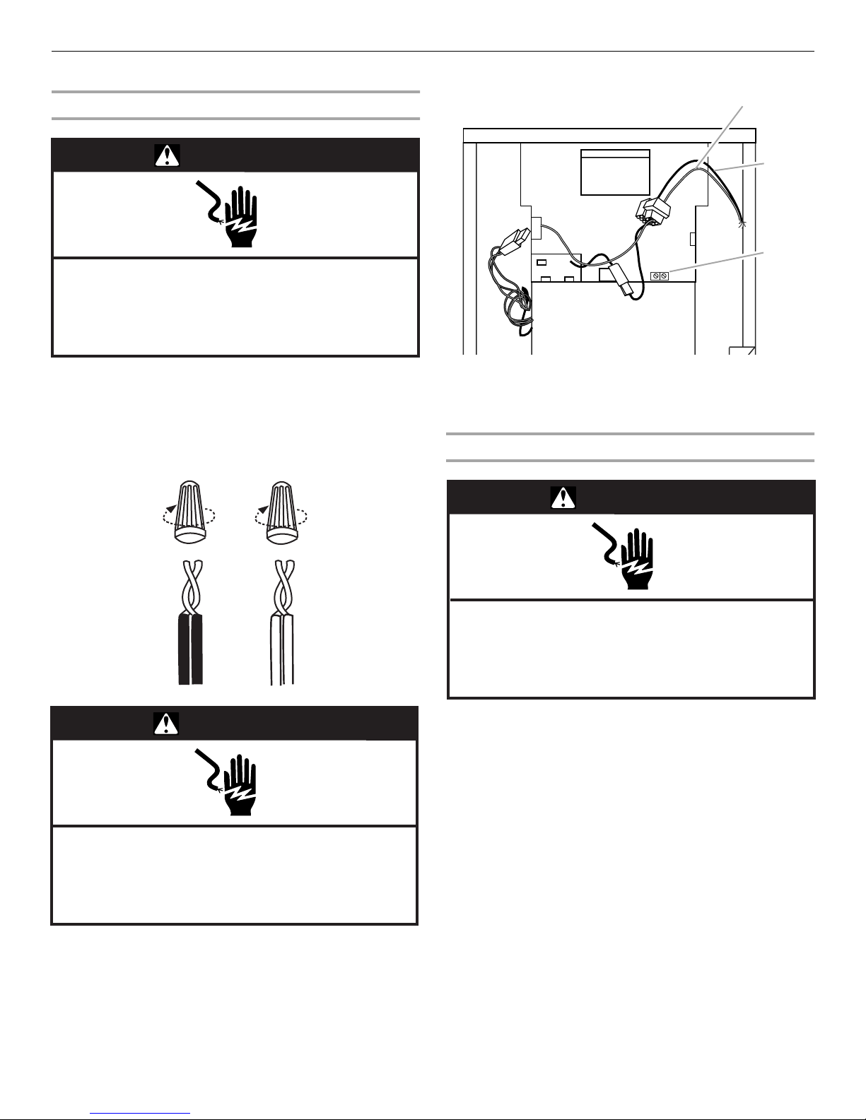
1. Disconnect all power supplies.
2. Remove the blower access panel.
3. Route the field supply wires to the air handler electrical
connection box.
4. Using UL listed wire nuts, connect the field supply wires to
the air handler (black to black and yellow to yellow).
A
B
C
GND
A. Connect yellow to yellow
B. Connect black to black
C. Connect ground wire to ground terminal marked “GND”
6. Replace the blower access panel.
208 Volt Conversion
WARNING
WARNING
Electrical Shock Hazard
Electrically ground air handler.
Connect ground wire to ground terminal marked “GND”.
Failure to do so can result in death or electrical shock.
5. Connect ground wire to terminal marked “GND.”
Electrical Shock Hazard
Disconnect all power supplies before servicing.
Replace all parts and panels before operating.
Failure to do so can result in death or electrical shock.
1. Disconnect all power supplies.
2. Remove the blower access panel.
3. Move the 2 connected black transformer leads from the
240 Volt terminal on the transformer to the 208 Volt terminal
on the transformer. See the appropriate wiring diagram for
your model.
5
Page 6
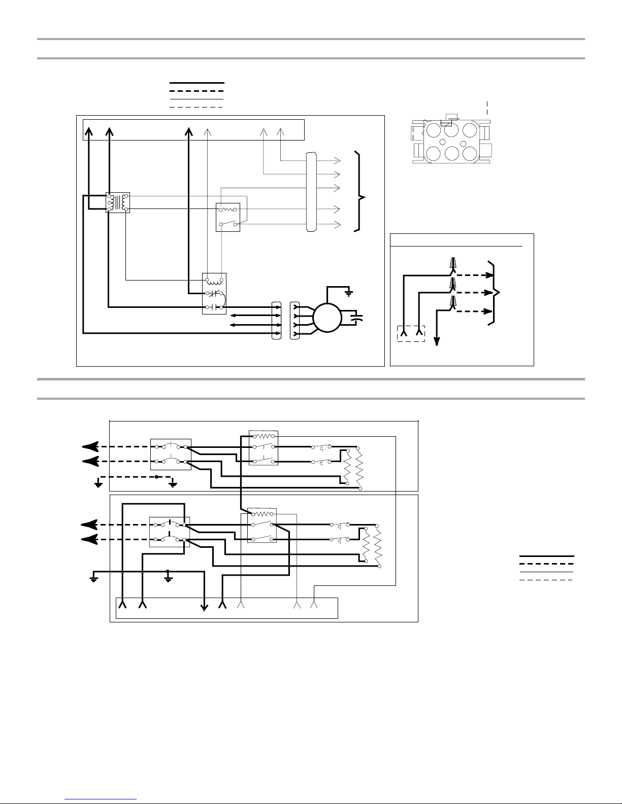
Wiring Diagram—Blower (PSC Motor)
Power (Factory Wired)
Power (Field Wired)
Control (Factory Wired)
Control (Field Wired)
23456
1
14 Y L2
14 BK L1
COM
208V
240V
TR
24
18 R
24V
18 BU
(H) (H)53
C
12
TD **
14 R
18 G
18 BU
3
6
4
1
5
2
BWR
++
Models 12, 25, 31 and 49
Will Be Factory Set to Low.
BK: Black W: White
R: Red
BU: Blue
++
14 BU (MED)
14 R (LO)
14 BK (HI)
14 Y (COM)
G: Green
Y: Yellow
18 BK
BU
4
R
3
BK
2
Y
1
+
W2
W1
C
G
R
MTR
BK
W
BU
G
R
BR / W
BR
GND
CAP
Control Circuit Wiring to
be 24 Volt, N.E.C. Class 2
Plug Pin
Location
1
4
** TD = Time Delay (Optional)
TR = Transformer
BWR = Blower Relay
MTR = Blower Motor
To
CAP = Motor Capacitor
by Others
Thermostat
GND = Ground Connection
Wiring Diagram - No Heat
Wire Nuts
by Others
14 Y (240V)
2
14 G
To
Ground Lug
14 BK
1
6-Pin
Plug
Amp 350781 - 1
6-Pin Cap
2
3
6
5
L1
L2 or
Neutral
15 Amp
Supply
Voltage
Wiring Diagram—Optional Electric Heat
CB2
*CB1
14 Y
To Blower
Ground Lug
GND
GND
12 BK
12 BK
12 BK
12 BK
14 G
220
208 / 240
Voltage
by Others
L1B
L2B
L1A
L2A
14 BK
12 6
14 R
3
18 BU
18 BU
4
5
3
12 Y
12 Y
5
3
12 Y
12 Y
SEQ2
SEQ1
18 BK
12 BK
4
1
12 BK
4
1
12 BK
12 BK
18 W
5
LS3
LS4
HE4
LS1
LS2
6-Pin Plug
2nd Stage
HE3
1st Stage
HE2
HE1
Heaters Used:
5 KW = HE1
7.5 & 10 KW = HE1 & HE2
15 KW = HE1, HE2 & HE3
20 KW = HE1, HE2, HE3 & HE4
* TB = Terminal Block (Optional)
* CB = Circuit Breaker (Optional)
SEQ = Sequencer
GND = Ground Lug
LS = Limit Switch
HE = Heater Element
Power (Factory Wired)
Power (Field Wired)
Control (Factory Wired)
Control (Field Wired)
6
Page 7
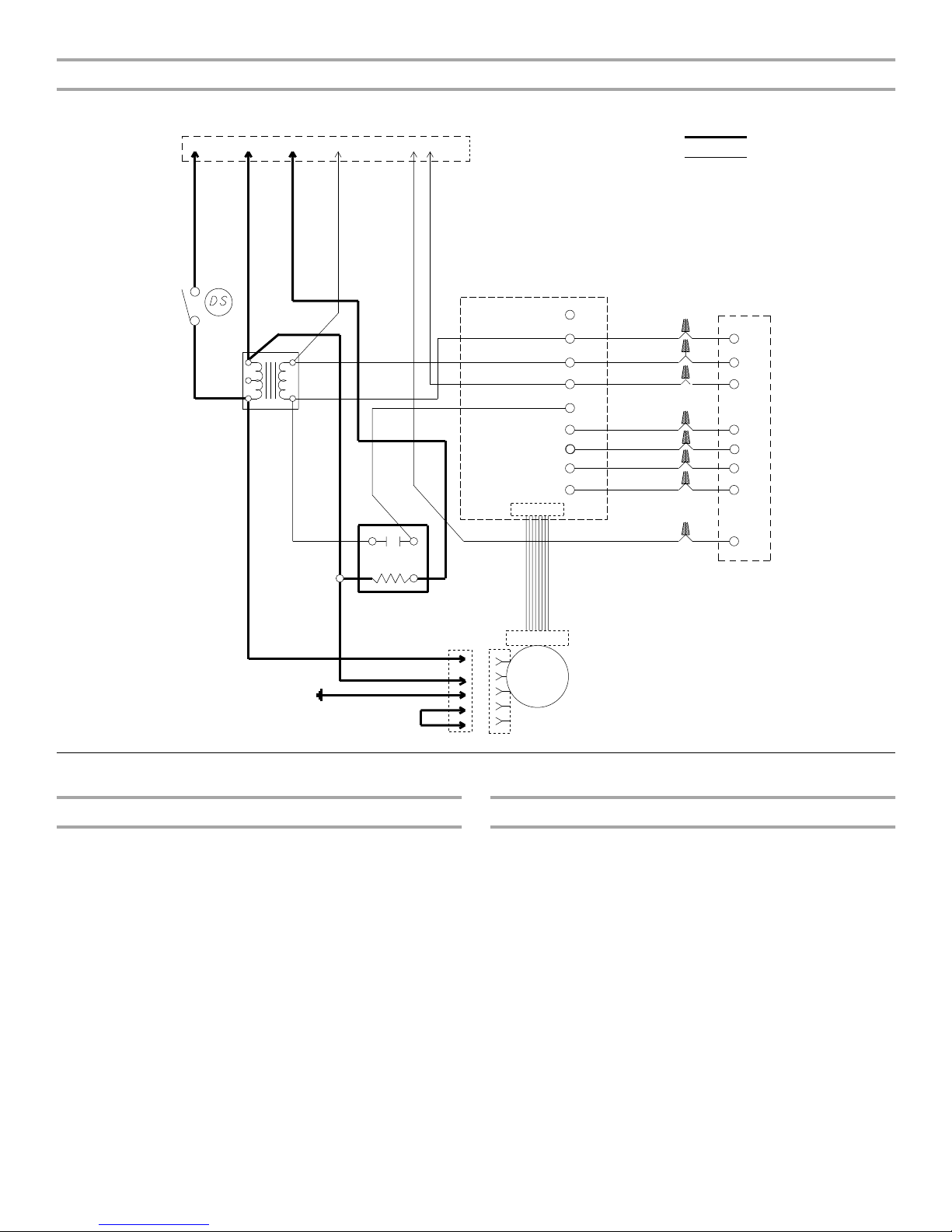
Wiring Diagram—Blower (Variable Speed Motor)
L2
14 Y
TR
18 BK
6-Pin Plug
14 R
24V
BU
24V
R
R 24V
18 BU
18 Y
1234 56
L1
14 BK
COM
208V
240V
18 W
18 BK
18 R
18 BU
18 W
Plug & Cap
Power (Factory Wired)
Control (Factory Wired
Transformer TR
Blower Motor MTR
Ground Connection GND
Blower Relay BWR
Control Board
Hum
18 R
R
C1
18 BU
EM
18 BK
W1
O
18 OR
18 BU/W
Y2
Y1
16-Pin
18 Y
18 G
G
R
C1
W2
O
Y2
Y1
G
Thermostat
240
BWR
5-Pin
Plug
18 BK
18 Y
18 G
GND
Complete Installation
Pre-Start Check
■ Is unit properly located, level, secure, and serviceable?
■ Is the wiring neat, correct, and in accordance with the wiring
diagram?
■ Is the air handler properly grounded and connected to a
properly sized fuse or circuit breaker?
■ Is the thermostat correctly wired, level, and in a good
location?
■ Are all access panels in place and secure?
■ Are any accessories properly installed?
(16)
18 BR
18 W
W1
16-Pin
5
4
MTR
Plug & Cap
3
2
1
5-Pin Cap
Check Airflow (PSC Motor)
Cooling blower speed—if cooling is used
■ For proper cooling operation, the airflow through the indoor
coil should be between 350 and 450 CFM per ton of cooling
capacity (or 350 - 450 CFM per 12,000 Btu/h) based on the
rating of the outdoor condensing unit.
■ The cooling blower speed is factory configured to provide
correct airflow for an outdoor condensing unit or heat pump
that matches the maximum cooling capacity rating of the air
handler.
■ If the outdoor condensing unit is smaller than the maximum
cooling capacity rating for the air handler, the cooling blower
speed may need to be changed. Refer to Blower
Performance Chart—PSC Motor.
IMPORTANT: The cooling blower speed must be set to provide a
minimum of 350 CFM airflow per ton (12,000 Btu/h) of outdoor
cooling capacity. The heating blower speed must be set
according to the heater installation instructions if installed.
7
Page 8
To change blower speed: Refer to “Wiring Diagram—
Blower (PCS Motor)” and “Wiring Diagram—Optional
Electric Heat.”
WARNING
Electrical Shock Hazard
Disconnect all power supplies before servicing.
Replace all parts and panels before operating.
Failure to do so can result in death or electrical shock.
1. Disconnect all power supplies.
2. Remove the air handler access panel.
3. Locate pin number 2 on the blower relay. Two black wires are
connected to this terminal pin. One connects to pin number
5 on the blower relay, one connects to either a red, blue or
black wire from terminal 1 (T1).
4. Remove the wire going to the 4-pin blower motor connector
from the splice.
5. Connect the blower lead (Red [LO], Blue [MED] or Black [HI])
for the correct blower speed onto the splice from the 4-pin
blower motor connector.
NOTE: Unused blower speeds are shipped from the factory
covered with a plastic cap. Remove this cap from the new
blower speed terminal and replace it over the factory-set
blower terminal.
6. Replace all panels.
7. Reconnect power.
Blower Performance Chart—PSC Motor
Air
Handler
Model
Blower
Speed
CFM @ ESP. - in W.C.
0.1 0.2 0.3 0.4 0.5 0.6
Check Airflow (Variable Speed Motor)
For proper cooling operation, the airflow through the indoor coil
should be between 350 and 450 CFM per ton of cooling capacity
(or 350 - 450 CFM per 12,000 Btu/h) based on the rating of the
outdoor condensing unit.
IMPORTANT: The cooling blower speed must be set to provide a
minimum of 350 CFM airflow per ton (12,000 Btu/h) of outdoor
cooling capacity.
To change blower speed: Refer to “Wiring Diagram—
Blower (Variable Speed Motor).”
WARNING
Electrical Shock Hazard
Disconnect all power supplies before servicing.
Replace all parts and panels before operating.
Failure to do so can result in death or electrical shock.
1. Disconnect all power supplies.
2. Locate the control board in the blower control box.
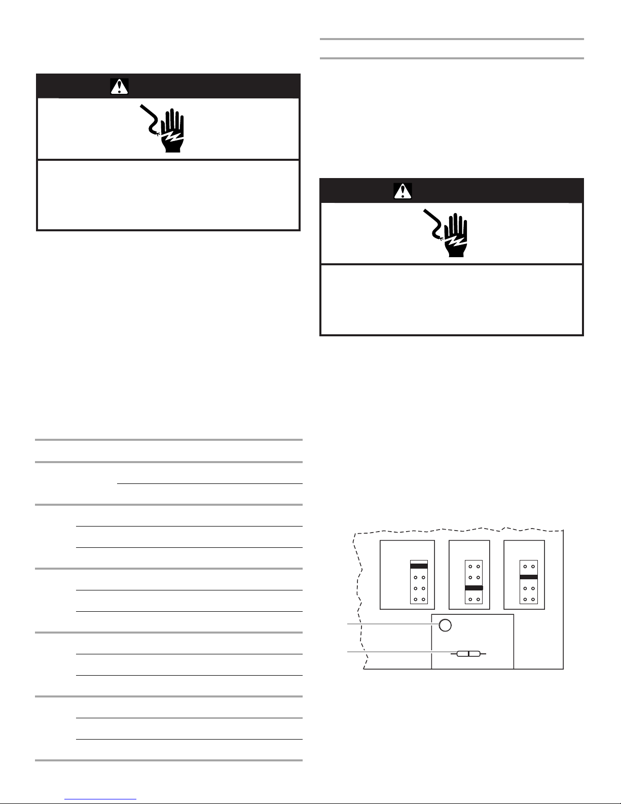
3. Set the HEAT and COOL taps by moving the board jumpers
to the A, B, C, or D positions (see Control Board Taps and
Dehumidify Resistor) based on the information found in the
Blower Performance Chart—Variable Speed Motor.
NOTE: If using a humidistat, the dehumidify resistor located
on the bottom right of the control board must be removed to
enable it. See Control Board Taps and Dehumidify Resistor.
The HUM terminal on the board must be connected to the
Normally Closed contact of the humidistat so that the board
senses an open circuit on high humidity. If a humidistat is
used, the dehumidify LED (see D1 below) will light when the
humidistat opens and the motor runs at reduced airflow.
WMB24
CC-1A
WMB36
CC-1A
WMB48
CC-1A
WMB60
CC-1A
Low 583 563 557 541 522 473
Medium 862 855 834 794 748 677
High 1,159 1,096 1,029 957 871 794
Low 838 827 808 778 746 699
Medium 1,265 1,255 1,235 1,215 1,173 1,118
High 1,358 1,340 1,311 1,282 1,231 1,179
Low 1,161 1,153 1,138 1,115 1,091 1,050
Medium 1,569 1,541 1,507 1,460 1,405 1,341
High 1,769 1,735 1,703 1,626 1,570 1,489
Low 1,632 1,566 1,581 1,544 1,482 1,417
Medium 2,163 2,103 2,058 2,000 1,947 1,855
High 2,398 2,394 2,266 2,180 2,109 2,042
8
Control Board Taps and Dehumidify Resistor
.
COOLHEATADJUST
NORM A
(+)
(–)
TEST
A
B
A. Dehumidify LED
B. Dehumidify resistor
4. If desired, adjust ADJUST tap from NORM: (+) will increase
airflow by 10% or (-) will decrease airflow by 12%
5. Reconnect all power supplies.
A
B
C
D
D1
DEHUMIDIFY
CUT TO ENABLE
B
C
D
Page 9

Blower Performance Chart—Variable Speed Motor
The versatility of the variable speed motor enables the air handler
to tailor its performance to the different modes of operation
encountered in heating and cooling. All variable speed air
handlers are capable of operation at more than one nominal
airflow rate.The operation of a variable speed air handler blower
at different airflow rates is determined by the control board taps
Before beginning the setup, become familiar with the information
found in the Blower Performance Chart—Variable Speed Motor.
The data in the Blower Performance Chart—Variable Speed
Motor is categorized by model size and mode of operation. Use
the information provided to determine the CFM taps needed for
cooling and heating.
and the thermostat. See the Blower Performance Chart—Variable
Speed Motor.
Blower Performance Chart—Variable Speed Motor
CFM @ E.S.P. - inches W.C.
Air Handler
Model
WMB36VB-1A Y1
WMB48VB-1A Y1
WMB60VB-1A Y1
NOTES:
■ Humidistat will reduce cooling airflow by 10% in high humidity.
■ Adjust the Control Board Tap (+) will increase airflow by 10%, while the Control Board Tap (-) will decrease airflow by 12%.
■ Adjust the Control Board Tap (-) test will cause the motor to run at 70% of full airflow. Use this for troubleshooting only.
■ At the start of a call for cooling, there is a short run at 82% of airflow for 7.5 minutes.
■ At the end of a call for cooling, there is a blower delay of 1 minute.
Energized Thermostat
Te rm in al
Y1/Y2
G
Y1/Y2
G
Y1/Y2
G
Control
Board Tap0.10.20.30.40.50.60.70.8
A 852 858 859 872 879 879 879 879
B 707 724 728 741 741 745 733 733
C 617 603 598 603 608 603
D 497 482 473 470 455 452 437 423
A 1,215 1,215 1,208 1,208 1,209 1,209 1,202 1,202
B 995 1,012 1,035 1,035 1,036 1,036 1,036 1,020
C 817 817 827 827 836 837 837 837
D 652 638 643 648 648 657 657 644
A 637 623 637 637 637 637 628 628
B 572 556 556 551 562 545 523 517
C 514 502 490 484 465 458 437 426
D 466 445 437 412 403 392 386 382
A 1,134 1,123 1,123 1,113 1,102 1,091 1,079 1,074
B 991 972 956 949 937 923 909 909
C 847 826 807 793 778 753 736 712
D 687 664 646 619 612 581 557 531
A 1,676 1,656 1,635 1,624 1,613 1,608 1,608 1,598
B 1,435 1,404 1,398 1,398 1,392 1,380 1,375 1,362
C 1,234 1,220 1,212 1,205 1,197 1,184 1,169 1,161
D 995 987 978 979 962 953 946 937
A 799 785 763 746 724 707 683 655
B 681 665 646 629 611 580 548 522
C 577 536 513 475 456 427 388 369
D 480 428 394 343 307 278
A 1,246 1,231 1,211 1,180 1,143 1,099 1,065 1,053
B 1,121 1,104 1,078 1,044 993 969 944 927
C 977 952 900 864 836 817 807 797
D 863 811 764 738 724 707 694 677
A 1,835 1,834 1,809 1,787 1,775 1,762 1,733 1,692
B 1,644 1,637 1,623 1,609 1,601 1,572 1,542 1,487
C 1,392 1,380 1,374 1,361 1,322 1,296 1,255 1,220
D 1,214 1,193 1,177 1,139 1,094 1,035 1,028 997
A 913 874 826 791 768 757 737 729
B 836 790 739 713 705 694 675 661
C 739 691 643 636 624 610 600 585
D 675 610 582 572 556 547 528 502
9
Page 10

SEQUENCE OF OPERATION
Cooling (cooling only or heat pump)
When the thermostat calls for cooling, the circuit between R and
G is completed, and the blower relay is energized. The Normally
Open contacts close, causing the indoor blower motor to
operate. The circuit between R and Y is also completed; this
circuit closes the contactor in the outdoor unit starting the
compressor and outdoor fan motor. Circuit R and O energizes
the reversing valve, switching it to the cooling position. (The
reversing valve remains energized as long as selector switch is
in the COOL position.)
Heating (electric heat only)
When the thermostat calls for heat, the circuit between R and W
is completed, and the heat sequencer relay is energized. A time
delay follows before the heating elements and the indoor blower
motor come on. Units with a second heat sequencer relay can be
connected with the first sequencer to W on the thermostat
subbase or connected to a second stage on the subbase.
Heating (heat pump)
When the thermostat calls for heat, the circuits between R and Y
and R and G are completed. Circuit R-Y energizes the contactor
starting the outdoor fan motor and the compressor. Circuit R
and G energizes the blower relay starting the indoor blower
motor.
If the room temperature should continue to fall, the circuit
between R and W 1 is completed by the second stage heat room
thermostat. Circuit R-W 1 energizes a heat sequencer relay. The
completed circuit will energize supplemental electric heat (if
available). Units with a second heat sequencer relay can be
connected with the first sequencer to W 1 on the thermostat or
connected to a second heating stage W 2 on the thermostat
subbase.
Variable Speed Features
Start
When called into operation, the variable speed motor will slowly
ramp up to normal operating speed. This eliminates the noise
and discomfort that results caused by the initial blast of air
encountered with standard air handlers. It can take up to
7.5 minutes to reach normal operating speed.
Continuous Blower Operation
The comfort level of the living space can be enhanced when
using this feature by allowing continuous circulation of air in
between calls for cooling or heating. The circulation of air
between calls for cooling or heating occurs at 50% of the
normal airflow rate (350 CFM minimum).
Reduced Airflow Operation
For situations where humidity control is a problem, the variable
speed motor can be enabled to operate at a 10% reduction in
the normal airflow rate under the control of a humidistat. This
can be achieved by connecting to a standard humidity control
that is normally closed and opens on humidity rise.
The Control Board
The control board regulates airflow selection and features LED
indicators that display operating mode, humidity control, and
airflow CFM. The red LED flashes once for each 100 CFM. For
example, if the operating CFM is 1200, the CFM LED will flash
12 times, then pause before repeating the 12-flash pattern.
Thermostat signals for emergency heat (EM), optional auxiliary
heat (W1), reversing valve (O), compressor (Y1), and blower (G)
are all indicated by lit LED’s on this board.
This model is designed for use with heat pumps as well as air
conditioning systems. The control board needs to sense a signal
on the “O” thermostat wire in order to use cooling delay timing.
For a straight air conditioning system, connect the “O” wire to the
thermostat “R” wire.
Some WMB air handlers are equipped with a variable speed
motor and will deliver a constant airflow within a wide range of
external static pressures. The variable speed blower offers the
following comfort features:
AIR HANDLER MAINTENANCE
IMPORTANT: Do not operate system without a filter. A filter is
required to protect the coil, blower, and internal parts from
excessive dirt and dust. See “Installation Configurations” for the
location of the filter in the unit cabinet and the service panel
giving access to unit filter. The filter is placed in the supply air
return duct by the installer.
■ Inspect air filters at least once a month and replace or clean
as required. Dirty filters are the most common cause of
inadequate heating or cooling performance.
ASSISTANCE OR SERVICE
If you need further assistance, you can write to the below
address with any questions or concerns:
Whirlpool
14610 Breakers Drive
Jacksonville, FL 32258
Please include a daytime phone number in your correspondence.
®
Home Cooling and Heating
■ Replace disposable filters. Cleanable filters can be cleaned
by soaking in mild detergent and rinsing with cold water.
■ Install new/clean filters with the arrows on the side pointing in
the direction of airflow.
■ Do not replace a cleanable (high velocity) filter with a
disposable (low velocity) filter unless return air system is
properly sized for it.
■ If water should start coming from the secondary drain line, a
problem exists which should be investigated and corrected.
Contact a qualified person.
Accessories
To order accessories, contact your Whirlpool© Home Cooling and
Heating dealer.
Electric Heat Kits
Refer to the accessory kit label on the front panel of the air
handler for electric heat kit accessory options and applications.
10
Page 11
11
Page 12

Keep this book and your sales slip together for future
reference. You must provide proof of purchase or installation
date for in-warranty service.
Write down the following information about your air handler to
better help you obtain assistance or service if you ever need it.
You will need to know the complete model and serial number. You
can find this information on the air handler rating plate.
Dealer name____________________________________________________
Address ________________________________________________________
Phone number __________________________________________________
Model number __________________________________________________
Serial number __________________________________________________
Installation date ________________________________________________
0650329-60
© 2006. All rights reserved.
Manufactured under license by Tradewinds Distributing Company, LLC., Coconut Grove, Florida
®Registered Trademark/TM Trademark of Whirlpool, U.S.A.,
Printed in U.S.A.
5/06
 Loading...