

Page 1
AIR HANDLER INSTALLATION INSTRUCTIONS
Table of Contents
AIR HANDLER SAFETY .................................................................1
INSTALLATION REQUIREMENTS................................................2
Tools and Parts ............................................................................3
Location Requirements................................................................ 3
Installation Configurations ...........................................................3
Electrical Requirements ...............................................................4
Ductwork Requirements ..............................................................4
INSTALLATION INSTRUCTIONS..................................................5
Inspect Shipment.........................................................................5
Install Ductwork............................................................................5
AIR HANDLER SAFETY
Install Blower—Cased Evaporator Coil........................................5
Install Filter....................................................................................6
Make Electrical Connections .......................................................7
Complete Installation..................................................................20
SEQUENCE OF OPERATION ......................................................23
Cooling—Cooling Only or Heat Pump.......................................23
Heating—Electric Heat Only ......................................................23
Heating—Heat Pump .................................................................23
AIR HANDLER MAINTENANCE ..................................................23
ASSISTANCE OR SERVICE.........................................................23
Accessories ................................................................................23
Recognize this symbol as a safety precaution.
Recognize Safety Symbols, Words and Labels
The following symbols and labels are used throughout this
manual to indicate immediate or potential hazards. It is the
owner’s responsibility to read and comply with all safety
information and instructions accompanying these symbols.
Failure to heed safety information increases the risk of serious
personal injury or death, property damage and/or product
damage.
WARNING
Hazards or unsafe practices could result in property
damage, product damage, severe personal injury or death.
Goodman 1
CAUTION
Hazards or unsafe practices may result in property
damage, product damage, personal injury or death.
CAUTION
Hazards or unsafe practices may result in property
or product damage.
Goodman 9
WARNING
Installation and repair of this unit should
be performed ONLY by individuals meeting
the requirements of an “Entry Level Technician”
as specified by the Air-Conditioning, Heating and
Refrigeration Institute (AHRI). Attempting to
install or repair this unit without such background may
result in product damage, personal injury or death.
Goodman 7
WARNING
HIGH VOLTAGE!
Disconnect ALL power before servicing.
Multiple power sources may be present.
Failure to do so may cause property damage,
personal injury or death.
Goodman 6
Placeholder
for Bar
Code
Whirlpool© Models WMAHM, WMAHV
WPIO-239E
Page 2
WARNING
This product is factory-shipped for use with 208/240/1/60
electrical power supply. DO NOT reconfigure this air
handler to operate with any other power supply.
Goodman 33
DANGER
WARNING
To avoid property damage, personal injury or death due to
electrical shock, this unit MUST have an uninterrupted,
unbroken electrical ground. The electrical ground circuit
may consist of an appropriately sized electrical wire
connecting the ground lug in the unit control box to the
building electrical service panel.
Other methods of grounding are permitted if performed
in accordance with the National Electric Code (NEC)
/American National Standards Institute (ANSI) /National
Fire Protection Association (NFPA) 70 and local/state
codes. In Canada, electrical grounding is to be in
accordance with the Canadian Electric Code (CSA) C22.1.
Goodman 34
CAUTION
When installing or servicing this equipment, safety
clothing, including hand and eye protection, is strongly
recommended. If installing in an area that has special
safety requirements (hard hats, etc.), observe these
requirements.
Goodman 35
WARNING
Goodman 37
To prevent the risk of property damage, personal injury, or
death, do not store combustible materials or use gasoline
or other flammable liquids or vapors in the vicinity of this
unit.
CARBON MONOXIDE POISONING HAZARD
Special Warning for Installation of Furnace or Air Handling
Units in Enclosed Areas such as Garages, Utility Rooms or
Parking Areas.
Carbon monoxide producing devices (such as an
automobile, space heater, gas water heater, etc.) should
not be operated in enclosed areas such as unventilated
garages, utility rooms or parking areas because of the
danger of carbon monoxide (CO) poisoning resulting from
the exhaust emissions. If a furnace or air handler is
installed in an enclosed area such as a garage, utility room
or parking area and a carbon monoxide producing device is
operated therein, there must be adequate, direct outside
ventilation.
This ventilation is necessary to avoid the danger of CO
poisoning which can occur if a carbon monoxide producing
device continues to operate in the enclosed area. Carbon
monoxide emissions can be (re)circulated throughout the
structure if the furnace or air handler is operating in any
mode.
CO can cause serious illness including permanent brain
damage or death.
IMPORTANT: The United States Environmental Protection
Agency (EPA) has issued various regulations regarding the
introduction and disposal of refrigerants in this unit. Failure to
follow these regulations may harm the environment and can lead
to the imposition of substantial fines. These regulations may vary
by jurisdiction. A certified technician must perform the installation
and service of this product. Should questions arise, contact your
local EPA office.
This product is designed and manufactured to permit installation
in accordance with national codes. It is the installer’s
responsibility to install this unit in accordance with national codes
and/or prevailing local codes and regulations.
Goodman 38
INSTALLATION REQUIREMENTS
These instructions are intended as a general guide only and do
not supersede any national or local codes in any way.
Compliance with all local, state, or national codes pertaining to
this type of equipment should be determined prior to installation.
Read this entire instruction manual, as well as the instructions
supplied in separate equipment, before starting the installation.
All models are designed for indoor installation only.
The installation of the air handler, field wiring, warm air ducts, etc.
must conform to the requirements of the National Electrical
Code, ANSI/NFPA No. 70 (latest edition) in the United States, and
any state laws, and local ordinances (including plumbing or
wastewater codes). Local authorities having jurisdiction should
be consulted before installation is made. Such applicable
regulations or requirements take precedence over the general
instructions in this manual.
2
Install the conditioned air plenum, ducts and air filters (not
provided) in accordance with NFPA 90B Standard for the
Installation of Warm Air Heating and Air-Conditioning Systems
(latest edition).
The air handler is provided with flanges for the connection of the
plenum and ducts.
Air filters (not provided) must be listed as Class 2 furnace air
filters.
The air handler may be used with an optional modular evaporator
coil (WMAH) in upflow, counterflow, or horizontal applications.
See “Installation Configuration Options” in “Installation
Configurations” for acceptable system configurations. The
mounting plates and the necessary hardware to connect the air
handler and modular evaporator coil cabinets together are
included with this air handler.
Page 3

An optional electric heater may be installed in this cabinet. For
electric heater accessory, refer to the electric heater rating plate
for specific information regarding the electric supply.
Do not remove the cabinet knockouts until it has been
determined which knockouts will need to be removed for the
installation.
Select any accessories that are to be included in this installation.
Select the final installation position which best suits the site
conditions. Consider required clearances, space, routing
requirements for refrigerant line, condensate disposal, filters,
ductwork, wiring, and accessibility for service. Refer to the air
handler rating plate on the air handler for specific information.
Tools and Parts
Gather the required tools and parts before starting installation.
Read and follow the instructions provided with any tools listed
here.
■ Louvered closet doors shall be sized with the minimum
opening required to provide minimum return air free area. See
Minimum Filter Requirements Chart.
■ Louvers installed in a closet to provide return air shall be
sized with minimum opening required to provide minimum air
return free area. See Minimum Filter Requirements Chart.
■ Return air plenum installed through the floor shall be sized
with minimum opening required to provide minimum return
free area. See Minimum Filter Requirements Chart.
■ If the free area is not known, assume a 25% free area for
wood or a 75% free area for metal louvers or grilles.
■ If the return air plenum is used, the return air grille should be
immediately in front of the opening in the plenum to allow for
the free flow of return air.
■ When not installed in front of the opening, there must be
adequate clearance around the unit to allow for the free flow
of return air.
Tools Needed
■ ⁵⁄₁₆" nut driver
■ Level
■ Screwdriver
■ Adjustable wrench
■ Tape measure
■ Hammer
■ Sealant
Parts Needed
Check local codes, check existing electrical supply, and read
“Ductwork Requirements,” and “Electrical Requirements,” before
purchasing parts.
■ UL listed wire connectors
Parts Supplied
The mounting plates and the necessary hardware to connect the
air handler and modular evaporator coil cabinets together are
included with the air handler.
Location Requirements
NOTE: When used on cooling applications, excessive sweating
may occur when the unit with optional evaporator coil is installed
in a very humid space.
■ If this unit is located in an area with high ambient temperature
and/or high humidity, the air handler may be subject to
nuisance sweating of the casing. On these installations, a
wrap of 2" (5.1 cm) fiberglass insulation with a vapor barrier is
recommended.
■ If the air handler is installed in an unconditioned space,
sealant should be applied around the electrical wires,
refrigerant tubing, and condensate lines where they enter the
cabinet.
■ Electrical wires should be sealed on the inside where they exit
the conduit opening. Sealant is required to avoid air leakage
into and condensate from forming inside the unit, control box,
and on electrical controls.
■ The unit must be installed in such a way as to allow free
access to the optional coil/filter compartment and blower/
control compartment.
Installation Clearances
Non-Duct Return Closet Installation
The unit can be installed in a closet with a false bottom to form a
return air plenum, with a return air plenum through the wall of the
closet, with an air duct routed through the floor, or with another
approved method. Louvered closet doors or return air grilles are
field supplied. Local codes may limit application of systems
without a duct return to single-story buildings.
Clearances and Accessibility
■ The unit can be positioned for upflow, counterflow, horizontal
right or horizontal left operation.
■ Zero clearance is allowed on all sides for combustible
materials.
■ 36" (91.4 cm) should be allotted on the door side for
maintenance and service.
■ To reduce the risk of rusting, do not install the unit blower
directly on the ground or on a floor that is likely to be wet. In
such environments, the unit must be elevated by use of a
sturdy, nonporous material.
Installation Configurations
For ease in installation, it is best to make any necessary coil
configuration changes before setting the unit in place. See
“Installation Configuration Options” later in this section.
Vertical Installations
Upflow/Counterflow
■ The unit must be supported on the bottom only and set on a
field-supplied supporting frame with an air return opening.
■ Securely attach the unit to the supporting frame.
Horizontal Installations
■ Horizontal installations can be left-hand or right-hand air
supply.
■ The cabinet must be supported by the building structure to
ensure cabinet integrity.
■ Ensure that there is adequate room to remove the blower
access panel if installing in the horizontal position.
Suspended Cabinet Installation
NOTE: Units cannot be installed in such a way that the blower
access panel is facing up or down.
■ The suspending means must be field fabricated, and should
consist of 2 “cradles” made by attaching 2 rods to a length of
angle iron or equivalent structural steel.
■ Locate the cradles so that they are as close as possible to the
ends of the unit (this will provide access for removal of major
components such as the blower assembly).
■ Provide enough clearance between the suspension rods and
the unit to allow removal of the blower access panel.
3
Page 4
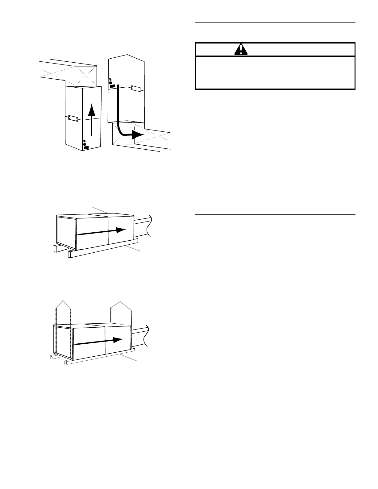
Installation Configuration Options
A
A
NOTE: Typical installations with optional WMAH modular
evaporator coil are shown.
Applications—Upflow/Counterflow
A
Electrical Requirements
WARNING
To avoid the risk of injury, electrical shock or death, the
furnace must be electrically grounded in accordance with
local codes or, in their absence, with the latest edition of the
National Electric Code (NEC).
Goodman 31
A
C
Upflow
A. Blower cabinet
B. Airflow direction
C. Coil cabinet
Attic Installation
Hanging Installation
B
A. Coil cabinet
B. Blower cabinet
C. Airflow direction
A
A. Blower cabinet
B. Airflow direction
C. Support
B
Counterflow
B
C
B
C
NOTES:
■ Use copper conductors only.
■ All field wiring must be done in accordance with National
Electrical Code, applicable requirements of UL and local
codes where applicable.
C
■ Electrical wiring, disconnect means and overcurrent
protection are to be supplied by the installer. Refer to the air
handler rating plate for maximum overcurrent protection,
minimum circuit ampacity, as well as operating voltage.
■ The power supply must be sized and protected according to
the specifications supplied on the product.
■ This air handler is factory-configured for 240-volt, single
phase, 60 cycles. For 208-volt applications, see “208-Volt
Conversion” in the “Make Electrical Connections” section.
■ For optional electric heater applications, see “Accessories.”
Refer to the instructions provided with the accessory for
proper installation.
Ductwork Requirements
■ Install the conditioned air plenum, ducts and air filters (not
provided) in accordance with NFPA 90B Standard for the
Installation of Warm Air Heating and Air-Conditioning
Systems (latest edition).
■ The air handler is provided with flanges for the connection of
the plenum and ducts.
■ All air filters (not provided) must be listed as Class 2 furnace
air filters.
■ The supply and return ductwork must be adequately sized to
meet the system’s air requirements and static pressure
capabilities. Ductwork should be insulated with a minimum of
1" (2.5 cm) thick insulation with a vapor barrier in the
conditioned areas or 2" (5.1 cm) minimum in unconditioned
areas.
■ The supply plenum should be the same size as the flanged
opening provided around the blower outlet and should
extend ideally at least 36" (91.4 cm) from the air handler
before turning or branching off plenum into the duct runs. The
plenum forms an extension of the blower housing and
minimizes air expansion losses from the blower.
A. Rods
B. Airflow direction
C. Support
4
Page 5
INSTALLATION INSTRUCTIONS
Inspect Shipment
The air handler is completely factory assembled, and all
components are performance tested. Each unit consists of a
blower assembly and controls in an insulated, galvanized factoryfinished enclosure. Knockouts are provided for electrical wiring
entrance.
■ Check the unit rating plate to confirm specifications are as
ordered.
■ Upon receipt of equipment, inspect it for possible shipping
damage. Be sure to examine the unit inside the carton if the
carton is damaged.
■ If damage is found, it should be noted on the carrier’s freight
bill. Damage claims should be filed with the carrier
immediately. Claims of shortages should be filed with the
seller within 5 days.
NOTE: If any damages are discovered and reported to the carrier,
do not install the unit as your claim may be denied.
Install Ductwork
IMPORTANT:
■ Install the ductwork in accordance with NFPA 90B Standard
for the Installation of Warm Air Heating and Air-Conditioning
Sytems (latest edition) and any local codes.
■ Connect the supply air duct to the flange on top of the unit. If
an isolation connector is used, it must be nonflammable.
■ A return air duct system is recommended. If the unit is
installed in a confined space or closet, the entire duct cross
sectional area must meet the minimum return air free area.
Install Blower—Cased Evaporator Coil
1. Secure the coil and blower together with the 2 connector
plates and screws supplied in the blower bag assembly.
2. Use 1 connector plate and 6 screws on each side of the unit.
3. If accessory electric heat is to be added, install now
according to the instructions shipped with the heater kit.
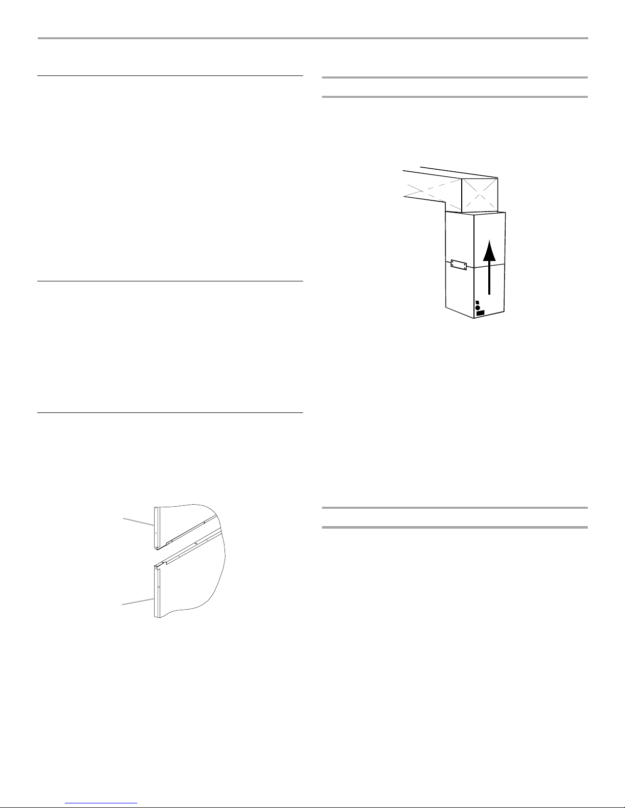
Upflow Installation
For upflow installations, the blower cabinet must sit on top of the
coil cabinet.
NOTE: All panels should be in place before installing the cabinet.
Upflow Installation
B
A
C
A. Blower cabinet
B. Airflow direction
C. Coil cabinet
1. Place the blower and coil cabinet assembly upright on the
return duct or duct opening. Ensure that there is ample
support for the cabinet assembly and all attached ductwork.
2. Connect the refrigerant and condensate drain connections
according to the evaporator coil installation instructions.
Ensure that the refrigerant and drain lines do not interfere with
service access to the unit.
3. Attach the supply ductwork.
4. Seal the connections between the unit and the ductwork as
required to reduce/eliminate air leakage.
Make electrical connections as specified in “Electrical
Connections.”
A
B
A. Top cabinet
B. Bottom cabinet
Counterflow Installation
For counterflow installations, the evaporator coil cabinet must sit
on top of the blower cabinet.
NOTE: All panels should be in place when installing the unit.
5
Page 6
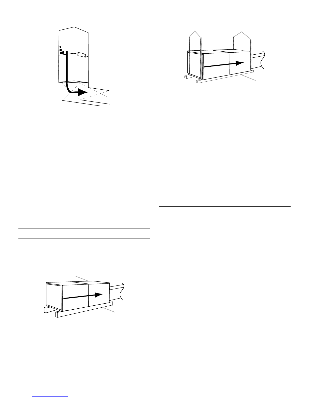
Counterflow Application
Hanging Installation
A
B
C
A. Coil cabinet
B. Blower cabinet
C. Airflow direction
NOTES:
■ Supply ductwork for counterflow applications must be
Class I.
■ If combustible ductwork is used, sheet metal protection is
required.
1. Place the blower and coil cabinet assembly supply outlet on
the supply duct or duct opening. Ensure there is ample
support for the unit and all attached ductwork.
2. Connect the refrigerant and condensate drain connections
according to the evaporator coil installation instructions.
Ensure refrigerant and drain lines do not interfere with service
access to the unit.
3. Attach the return ductwork.
4. Seal the connections between the unit and the ductwork as
required to reduce/eliminate air leakage.
5. Make electrical connections as specified in “Electrical
Connections.”
Horizontal Installation
For horizontal installations, the coil cabinet must be upstream of
the blower cabinet.
NOTE: All panels should be in place when installing the unit.
A
A
B
C
A. Rods
B. Airflow direction
C. Support
1. Set the unit near its final installation place. The unit must be
supported along the entire length of the unit.
2. Install rubber isolation pads to reduce sound and vibration
transmission.
3. Ensure there is ample support for the unit and all attached
ductwork.
4. If installed above a finished ceiling or living space, be sure to
place a secondary drain pan under the entire unit, and pipe
the drain separately from the main condensate drain.
5. Connect the refrigerant and condensate drain connections
according to the coil section installation instructions.
6. Ensure that the refrigerant and drain lines do not interfere with
service access to the unit.
7. Attach the return and supply ductwork.
8. Seal connections.
9. Make electrical connections as specified in “Electrical
Connections.”
Install Filter
Filters are not supplied with these air handlers. It is the installer's
responsibility to install properly sized filters in accordance with
the Minimum Filter Requirements Chart.
■ The filter size is determined by the “Nominal Tons Air
Conditioning and Nominal Airflow” (see chart).
■ Areas and dimensions shown for cleanable filters are based
on filters rated at 600 ft per minute face velocity.
Attic Installation
A
B
A. Blower cabinet
B. Airflow direction
C. Support
6
C
Page 7
■ Typical filter sizes are shown; however, any combination of
filters whose area equals or exceeds the minimum area
shown is satisfactory.
Minimum Filter Requirements Chart
2
Nominal Tons
Air Conditioning
and Nominal
Airflow
Up to 2 Tons
800 to 900 CFM
2¹⁄₂ Tons
900 to 1,000 CFM
3 Tons
1,100 to 1,300 CFM
3¹⁄₂ Tons
1,300 to 1,500 CFM
4 Tons
1,500 to 1,700 CFM
Sq. In. (cm
and Nominal Size—In. (cm)
Disposable
Filters
432 (2,787)
20 x 25
(50.8 x 63.5)
480 (3,097)
20 x 30
(50.8 x 76.2)
576 (3,716)
*14 x 25
(35.6 x 63.5)
672 (4,335)
*16 x 25
(40.6 x 63.5)
768 (4,955)
*20 x 25
(50.8 x 63.5)
) Surface Area
Cleanable
Filters
260 (1,677)
15 x 20
(38.1 x 50.8)
288 (1,858)
14 x 25
(35.6 x 63.5)
346 (2,232)
16 x 25
(40.6 x 63.5)
404 (2,606)
20 x 25
(50.8 x 63.5)
461 (2,974)
20 x 25
(50.8 x 63.5)
Minimum
Return Air
Free
Area—sq.
2
in. (cm
260 (1,677)
288 (1,858)
346 (2,232)
404 (2,606)
461 (2,974)
)
WARNING
Goodman 40
To avoid the risk of personal injury, wiring to the unit must
be properly polarized and grounded.
WARNING
All wiring must comply with applicable local and national
codes. Type and location of fused disconnect switch(es)
must comply with all applicable codes and provide overcurrent protection as shown on the nameplate.
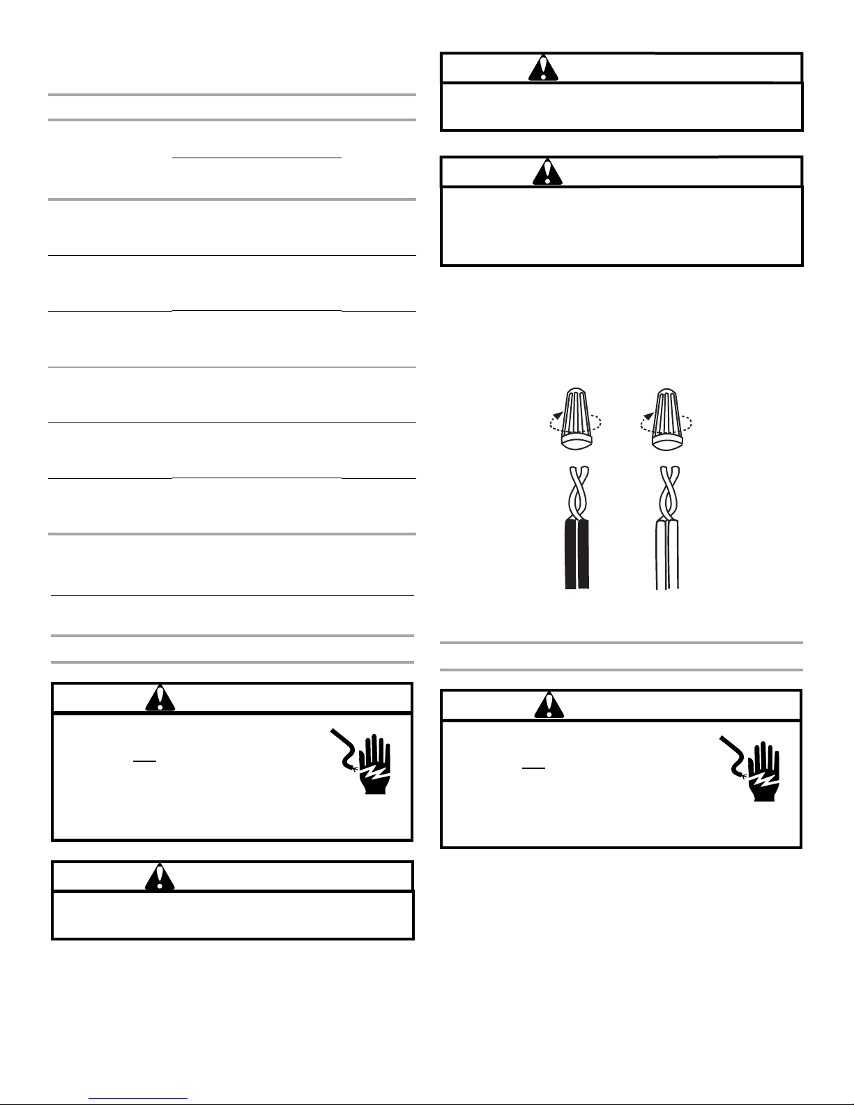
1. Disconnect all power supplies.
2. Remove the blower access panel.
3. Route the field supply wires to the air handler electrical
connection box.
4. Using UL-listed wire connectors, connect the field supply
wires to the air handler (black to black and yellow to yellow).
Goodman 41
5 Tons
1,900 to 2,100 CFM
*2 disposable filters required for these units
If a central return air filter-grille is used, the air handler does not
require a filter.
960 (6,194)
*20 x 30
(50.8 x 76.2)
576 (3,716)
24 x 25
(61 x 63.5)
576 (3,716)
Make Electrical Connections
208/240 Volt Installations
WARNING
HIGH VOLTAGE!
Disconnect ALL power before servicing.
Multiple power sources may be present.
Failure to do so may cause property damage,
personal injury or death.
To avoid the risk of fire or equipment damage, use
copper conductors.
Goodman 6
WARNING
Goodman 22
5. Connect ground wire to terminal marked “GND.”
6. Replace the blower access panel.
208 Volt Conversion
WARNING
HIGH VOLTAGE!
Disconnect ALL power before servicing.
Multiple power sources may be present.
Failure to do so may cause property damage,
personal injury or death.
1. Disconnect all power supplies.
2. Remove the blower access panel.
3. Move the 2 connected black transformer leads from the
240 Volt terminal on the transformer to the 208 Volt terminal
on the transformer. See the appropriate wiring diagram for
your model.
Goodman 6
7
Page 8
WARNING
Disconnect ALL power before servicing.
Goodman 6 Long
HIGH VOLTAGE!
Multiple power sources may be present.
Failure to do so may cause property damage, personal injury or death.
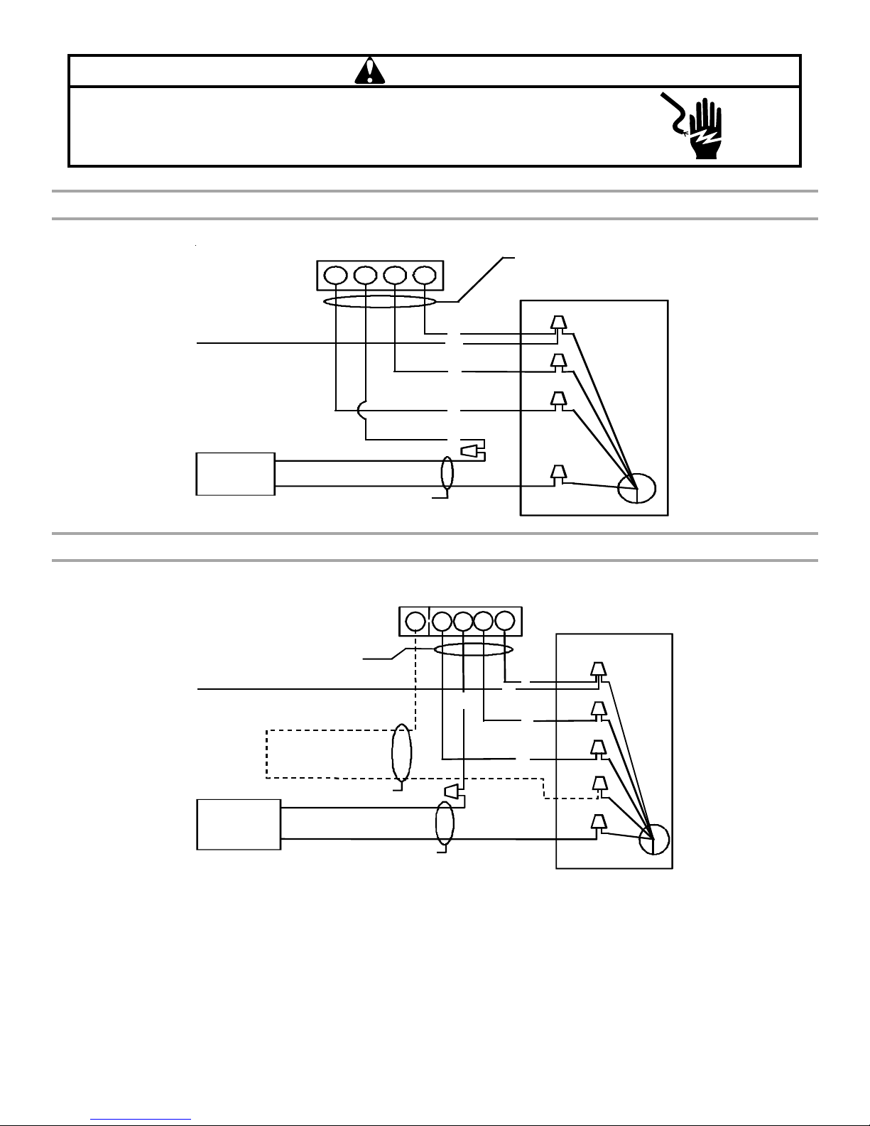
WMAHM Wiring Diagram—Low Voltage for Cooling Unit with Optional Heat Kit—10KW and Below
#18 Gauge - 4 Wires With Cooling,
3 Wires Without Cooling
Unit
Red
Green
White
Blue
To Comfort Alert
Module (If Used)
Contactor
Coil
To Condensing
Unit 24V Connections
Room Thermostat
WY
#18 Gauge - 2 Wires
G
R
R
R
G
W
Y
WMAHM Wiring Diagram—Low Voltage for Cooling Unit with Optional Heat Kit—15KW and Above
Room Thermostat
#18 Gauge - 4 Wire With Cooling,
3 Wire Without Cooling
To Comfort Alert
Module (If Used)
Contactor
Coil
W2
Outdoor
Thermostat
(Optional)
#18 Gauge - 2 Wires
To Condensing Unit
24V Connections
#18 Gauge - 2 Wires
GR
W
Y
R
Y
R
G
W
Unit
Red
Green
White
Brown
Blue
8
Page 9
WARNING
Disconnect ALL power before servicing.
Goodman 6 Long
HIGH VOLTAGE!
Multiple power sources may be present.
Failure to do so may cause property damage, personal injury or death.
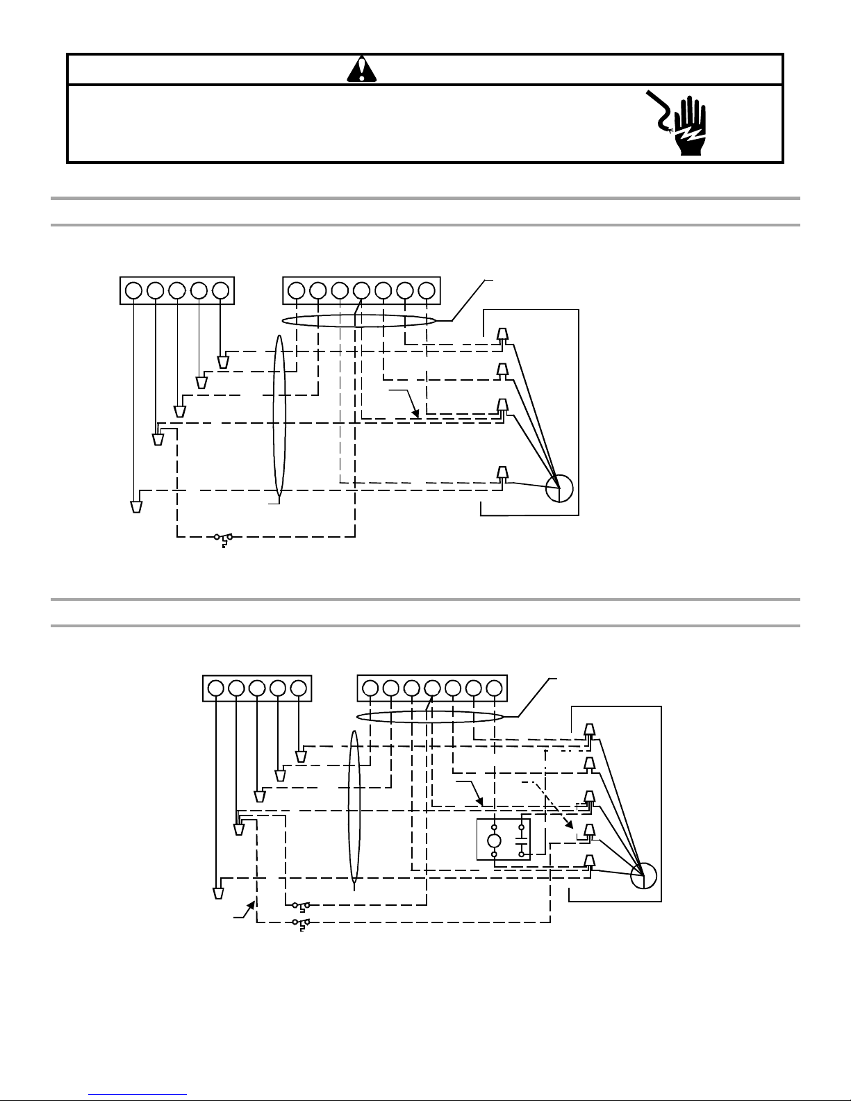
WMAHM System Composite Diagram—800 to 2000—10KW and Below
Heat Pump
W2
C
BU W OR Y R
O
Y
BU
#18 Gauge - 5 Wire
R
Y
OR
W
Y
R
Conventional
Room Thermostat
W2
O
C
G
See
Note 3
RE
W
R
BR
G
BU
#18 Gauge - 7 Wire
WMAHM Unit
Red
Green
White
Blue
Color Symbols
RRed
Y Yellow
BU Blue
V Violet
BR Brown
OR Orange
W White
PK Pink
G Green
Outdoor Thermostat (Optional) Closed on Temperature Fall
#18 Gauge - 6 Wire Needed When Outdoor Thermostat Is Used
WMAHM System Composite Diagram—1200 to 2000—Above 10KW
Heat Pump
W2
O
C
BU W OR Y R
See Note 1
YR
R
Y
OR
W
BU
#18 Gauge - 5 Wire
Outdoor Thermostat - 1
Outdoor Thermostat - 2
YOC GR
Conventional
Room Thermostat
W2
See
Note 3
W
EHR
G
BU
E
BR
1
3
R
See
Note 2
2
4
#18 Gauge - 7 Wire
WMAHM Unit
Red
Green
White
Brown
Blue
NOTES:
■ OT—Outdoor Thermostat (optional)
■ EHR—Emergency Heat Relay (optional)
1. Outdoor thermostat (OT-1) should be the first to close and the
first to open.
2. If the outdoor thermostat is not used, tie the white and brown
wires from the air handler together.
3. Remove wire when using the outdoor thermostat. #18 gauge
7 wire needed when 2 outdoor thermostats are used.
9
Page 10
WARNING
Disconnect ALL power before servicing.
Goodman 6 Long
HIGH VOLTAGE!
Multiple power sources may be present.
Failure to do so may cause property damage, personal injury or death.
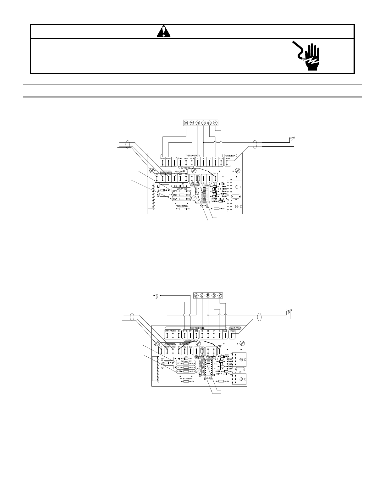
WMAHV Single-Stage Cooling with Single- or 2-Stage Heating
Cooling Only—2-Stage Heat Thermostat
Condensing Unit
To Comfort Alert
Module (If Used)
See Note 3
See Note 4
Please refer
to manual
for proper
DIP switch (CFM)
configuration.
Room Thermostat
If Needed
nd
2
Stage Heater
st
1
Stage Heater
Humidistat
(Optional)
See Note 4
NOTES:
1. Y/Y2 enables high speed fan cooling.
2. E/W1 enables low speed fan heating. W/W2 enables high
speed fan heating.
4. Cut HUM PJ6 jumper if using humidistat. Humidistat opens
on humidity rise.
5. DIP Switch 4 must be in the “ON” position.
3. OT1 PJ4 must be cut for this configuration.
Cooling Only—2-Stage Heat—1st Room Thermostat and 2nd Outdoor Thermostat
Outdoor Thermostat
Condensing Unit
To Comfort Alert
Module (If Used)
See Note 3
See Note 4
Please refer
to manual
for proper
DIP switch (CFM)
configuration.
NOTES:
st
■ 1
Stage enabled through room thermostat.
nd
■ 2
Stage enabled through closed outdoor thermostat.
1. Y/Y2 enables high speed fan cooling.
2. E/W1 enables low speed fan heating. E/W1 with outdoor
thermostat closed enables high speed fan heating.
Room Thermostat
If Needed
nd
2
Stage Heater
st
1
Stage Heater
3. OT1 PJ4 must be cut for this configuration.
4. Cut HUM PJ6 jumper if using humidistat. Humidistat opens
on humidity rise.
5. DIP Switch 4 must be in the “ON” position.
Humidistat
(Optional)
See Note 4
10
Page 11
WARNING
Disconnect ALL power before servicing.
Goodman 6 Long
HIGH VOLTAGE!
Multiple power sources may be present.
Failure to do so may cause property damage, personal injury or death.
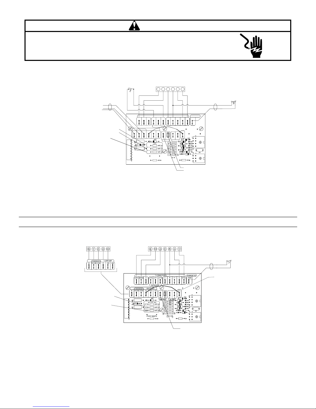
Cooling Only—2-Stage Heat—Outdoor Thermostat Enabled
Outdoor Thermostat
Condensing Unit
To Comfort Alert
Module (If Used)
See Note 3
See Note 4
See Note 5
NOTES:
st
■ 1
Stage enabled through room thermostat.
nd
■ 2
Stage enabled through closed outdoor thermostat.
1. Y/Y2 enables high speed fan cooling.
2. E/W1 enables low speed fan heating. W/W2 with outdoor
thermostat closed enables high speed fan heating.
E\W1
W/W2 O OTC OT1
CONDENSER
YCON
R
COM OW2W2 ED
HUM
Please refer
to manual
for proper
DIP switch (CFM)
configuration.
HEATPUMP
OT1
OT2
PN B1368274
W1
Room Thermostat
W1 W2
RG
Y
C
Humidistat
(Optional)
See Note 5
THERMOSTATS
OT2 C RY1
OUTDOOR
W1 W2
HEATER
HC
T
IW
S
P
I
D
If Needed
CR
24 VAC
FFO
N
O
HUMIDISTAT
HUM
Y/Y2G
Y1
nd
2
Stage Heater
st
Stage Heater
1
3. OT1 PJ4 must be cut for this configuration.
4. OT2 PJ2 must be cut for this configuration.
5. Cut HUM PJ6 jumper if using humidistat. Humidistat opens
on humidity rise.
6. DIP Switch 4 must be in the “ON” position.
WMAHV Heat Pump with Single- or 2-Stage Heating and Options for Emergency Heat
Heat Pump—1-Stage Emergency Heat and 1-Stage Auxiliary Heat
NOTES:
1. Y enables high speed fan cooling.
2. E and W2 enable high speed fan heating.
3. If OT2 PJ2 jumper is cut, E and W2 enable low speed fan
heating.
Heat Pump
See Note 3
See Note 4
Please refer
to manual
for proper
DIP switch (CFM)
configuration.
Room Thermostat
Humidistat
If Needed
(Optional)
See Note 4
st
Stage Heater
1
4. Cut HUM PJ6 jumper if using humidistat. Humidistat opens
on humidity rise.
5. DIP Switch 4 must be in the “ON” position.
Remove
Production
Wire Y1-O
11
Page 12
WARNING
Disconnect ALL power before servicing.
Goodman 6 Long
HIGH VOLTAGE!
Multiple power sources may be present.
Failure to do so may cause property damage, personal injury or death.
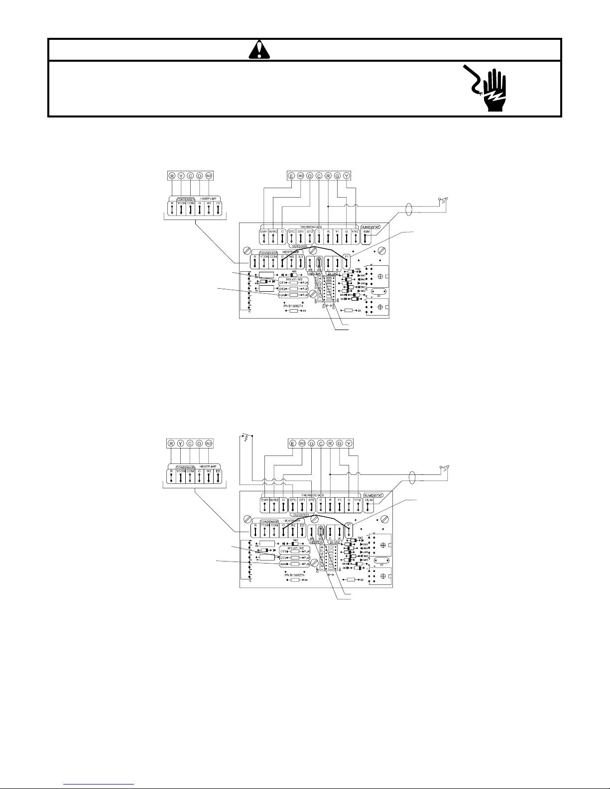
Heat Pump—2-Stage Emergency Heat and 1-Stage Auxiliary Heat
Heat Pump
See Note 3
See Note 4
Please refer
to manual
for proper
DIP switch (CFM)
configuration.
NOTES:
1. Y enables high speed fan cooling.
2. E enables low speed fan heating. W2 enables high speed fan
heating.
3. OT1 PJ4 must be cut for this configuration.
Room Thermostat
If Needed
4. Cut HUM PJ6 jumper if using humidistat. Humidistat opens
5. DIP Switch 4 must be in the “ON” position.
2nd Stage Heater
st
Stage Heater
1
on humidity rise.
Humidistat
(Optional)
See Note 4
Remove
Production
Wire Y1-O
Heat Pump—2-Stage Emergency Heat and 2-Stage Auxiliary Heat—1 Outdoor Thermostat
Heat Pump
See Note 4
NOTES:
st
■ 1
Stage auxiliary heat enabled by room thermostat.
nd
■ 2
Stage auxiliary heat enabled by room thermostat and
outdoor thermostat.
1. Y enables high speed fan cooling.
2. E enables low speed fan heating. W2 enables low speed fan
heating. W2 with OT2 closed enables high speed fan heating.
Outdoor Thermostat
See Note 3
Please refer
to manual
for proper
DIP switch (CFM)
configuration.
Room Thermostat
Humidistat
If Needed
HCTIWS
FFO
N
O
2nd Stage Heater
st
Stage Heater
1
(Optional)
See Note 4
Remove
Production
Wire Y1-O
3. OT2 PJ2 must be cut for this configuration.
4. Cut HUM PJ6 jumper if using humidistat. Humidistat opens
on humidity rise.
5. DIP Switch 4 must be in the “ON” position.
12
Page 13
WARNING
Disconnect ALL power before servicing.
Goodman 6 Long
HIGH VOLTAGE!
Multiple power sources may be present.
Failure to do so may cause property damage, personal injury or death.
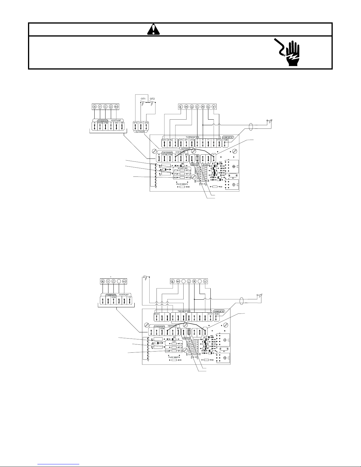
Heat Pump—2-Stage Emergency Heat and 2-Stage Auxiliary Heat—2 Outdoor Thermostats
Heat Pump
See Note 3
See Note 4
See Note 5
Please refer
to manual
for proper
DIP switch (CFM)
configuration.
NOTES:
■ No auxiliary heat in heat pump mode until outdoor thermostat
closes.
1. Y enables high speed fan cooling.
2. E enables low speed fan heating. W2 with OT1 closed
enables low speed fan heating. W2 with OT2 closed enables
high speed fan heating.
Room Thermostat
Humidistat
If Needed
2nd Stage Heater
st
Stage Heater
1
(Optional)
See Note 5
Remove
Production
Wire Y1-O
3. OT1 PJ4 must be cut for this configuration.
4. OT2 PJ2 must be cut for this configuration.
5. Cut HUM PJ6 jumper if using humidistat. Humidistat opens
on humidity rise.
6. DIP Switch 4 must be in the “ON” position.
Heat Pump—2-Stage Emergency Heat and 1-Stage Auxiliary Heat—1 Outdoor Thermostat
Heat Pump
R YCON O W2
See Note 3
See Note 5
NOTES:
■ No auxiliary heat in heat pump mode until outdoor thermostat
closes.
1. Y enables high speed fan cooling.
2. E enables low speed fan heating. W2 with OT2 closed
enables high speed fan heating.
O
See Note 4
Outdoor Thermostat
R
YCON O W2
Please refer
to manual
for proper
DIP switch (CFM)
configuration.
OUTDOOR
OT1
OT2
Room Thermostat
W2W1
O
OT2W1OT1OW/W2 OTC
G
If Needed
W2
CR
24 VAC
GY1RC
Y1
2nd Stage Heater
st
1
Stage Heater
Humidistat
(Optional)
See Note 5
Remove
Production
Wire Y1-O
3. OT1 PJ4 must be cut for this configuration.
4. OT2 PJ2 must be cut for this configuration.
5. Cut HUM PJ6 jumper if using humidistat. Humidistat opens
on humidity rise.
6. DIP Switch 4 must be in the “ON” position.
13
Page 14
WARNING
Disconnect ALL power before servicing.
Goodman 6 Long
HIGH VOLTAGE!
Multiple power sources may be present.
Failure to do so may cause property damage, personal injury or death.
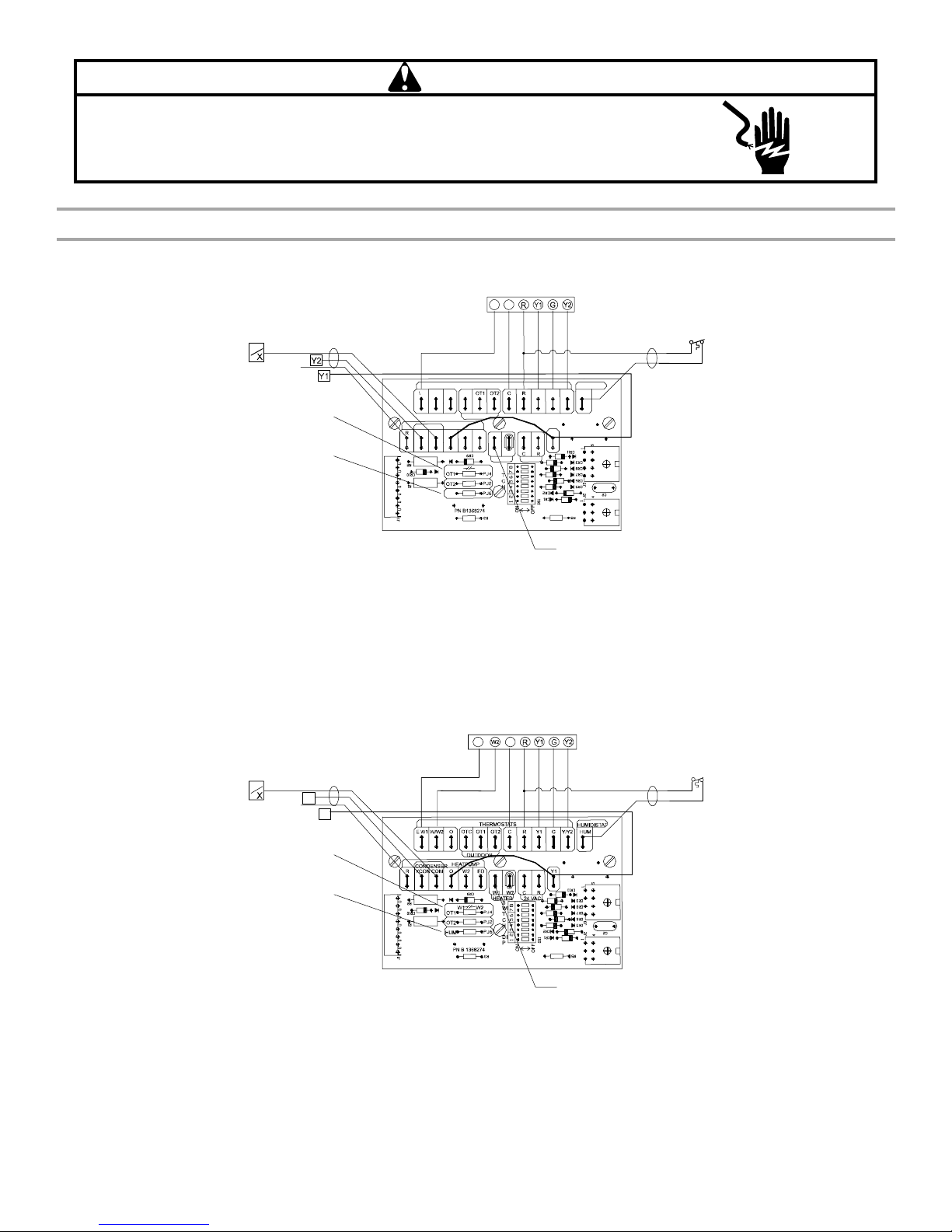
WMAHV 2-Stage Cooling with Conventional 2-Stage Thermostat
2-Speed Cooling Only—1-Stage Electric Heat
2-Speed Condensing Unit
C
To Comfort Alert
Module (If Used)
See Note 2
CONDENSER
YCON
See Note 4
Please refer
to manual
for proper
DIP switch (CFM)
configuration.
NOTES:
1. Y enables low speed fan cooling. Y/Y2 enables high speed
fan cooling.
2. E/W1 enables high speed fan heating.
3. If OT1 PJ4 jumper is cut, E/W1 enables low speed fan
heating.
OUTDOOR
HEATPUMP
COM O W2 ED
W1
HUM
W2
Room Thermostat
C
W
Humidistat
(Optional)
See Note 4
THERMOSTATS
W1 W2
HEATER
S
WI
DI
P
If Needed
Y1W/W2EW1 OOTC
24 VAC
HUMIDISTAT
HUMGY/Y2
Y1
st
Stage Heater
1
4. Cut HUM PJ6 jumper if using humidistat. Humidistat opens
on humidity rise.
5. DIP Switch 4 must be in the “OFF” position.
2-Speed Cooling Only—2-Stage Heat Thermostat
2-Speed Condensing Unit
C
To Comfort Alert
Module (If Used)
NOTES:
1. Y1 enables low speed fan cooling. Y/Y2 enables high speed
fan cooling.
2. E/W1 enables high speed fan heating.
3. If OT1 PJ4 jumper is cut, E/W1 enables low speed fan
heating.
Y2
Y1
See Note 2
See Note 4
\
Please refer
to manual
for proper
DIP switch (CFM)
configuration.
Room Thermostat
C
W
Humidistat
If Needed
(Optional)
See Note 4
st
1
Stage Heater
4. Cut HUM PJ6 jumper if using humidistat. Humidistat opens
on humidity rise.
5. DIP Switch 4 must be in the “OFF” position.
14
Page 15
WARNING
Disconnect ALL power before servicing.
Goodman 6 Long
HIGH VOLTAGE!
Multiple power sources may be present.
Failure to do so may cause property damage, personal injury or death.
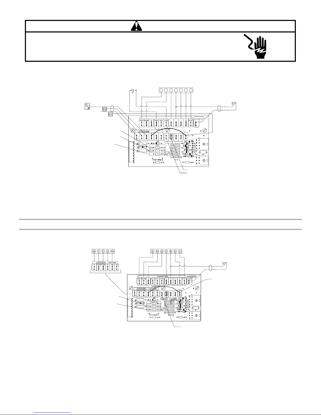
2-Speed Cooling Only—2-Stage Heat—Outdoor Thermostat Enabled
Outdoor Thermostat
2-Speed Condensing Unit
To Comfort Alert
Module (If Used)
See Note 3
See Note 4
YCONR
COMW2W2 ED
See Note 5
Please refer
to manual
for proper
DIP switch (CFM)
configuration.
NOTES:
1. Y1 enables low speed fan cooling. Y/Y2 enables high speed
fan cooling.
2. E/W1 enables low speed fan heating. W/W2 with outdoor
thermostat closed enables high speed fan heating.
3. OT1 PJ4 must be cut for this configuration.
Room Thermostat
W1 W2
R
C
If Needed
THERMOSTATS
C RY1Y1HUM
OUTDOOR
HEATPUMP
W1 W2
CR
HEATER
W1
HUM
HCTIWS
PID
NO
4. OT2 PJ2 must be cut for this configuration.
5. Cut HUM PJ6 jumper if using humidistat. Humidistat opens
on humidity rise.
6. DIP Switch 4 must be in the “OFF” position.
24 VAC
Y1 Y2
F
FO
G
HUMIDISTAT
2nd Stage Heater
st
Stage Heater
1
Humidistat
(Optional)
See Note 5
WMAHV Heat Pump with Single- or 2-Stage Heating with Conventional Thermostat and Options for Emergency Heat
Heat Pump—1-Stage Emergency Heat and 1-Stage Auxiliary Heat
NOTES:
1. Y enables high speed fan cooling.
2. E and W2 enable high speed fan heating.
3. If OT2 PJ2 jumper is cut, E and W2 enable low speed fan
heating.
Heat Pump
See Note 3
See Note 4
Please refer
to manual
for proper
DIP switch (CFM)
configuration.
Room Thermostat
Humidistat
If Needed
(Optional)
See Note 4
Remove
Production
Wire Y1-O
st
Stage Heater
1
4. Cut HUM PJ6 jumper if using humidistat. Humidistat opens
on humidity rise.
5. DIP Switch 4 must be in the “ON” position.
15
Page 16
WARNING
Disconnect ALL power before servicing.
Goodman 6 Long
HIGH VOLTAGE!
Multiple power sources may be present.
Failure to do so may cause property damage, personal injury or death.
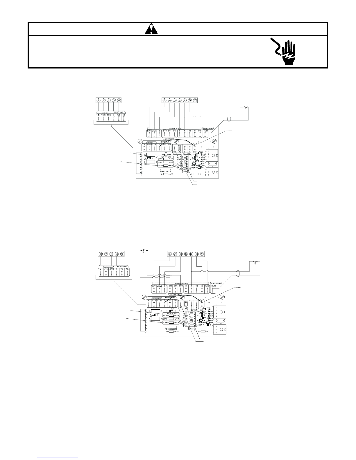
Heat Pump—2-Stage Emergency Heat and 1-Stage Auxiliary Heat
Heat Pump
See Note 3
See Note 4
Please refer
to manual
for proper
DIP switch (CFM)
configuration.
NOTES:
1. Y enables high speed fan cooling.
2. E enables low speed fan heating. W2 enables high speed fan
heating.
3. OT1 PJ4 must be cut for this configuration.
Room Thermostat
If Needed
4. Cut HUM PJ6 jumper if using humidistat. Humidistat opens
5. DIP Switch 4 must be in the “ON” position.
Humidistat
(Optional)
See Note 4
2nd Stage Heater
st
1
Stage Heater
on humidity rise.
Remove
Production
Wire Y1-O
Heat Pump—2-Stage Emergency Heat and 2-Stage Auxiliary Heat—1 Outdoor Thermostat
Heat Pump
See Note 4
NOTES:
1. Y enables high speed fan cooling.
2. E enables low speed fan heating. W2 enables low speed fan
heating. W2 with OT2 closed enables high speed fan heating.
3. OT1 PJ4 must be cut for this configuration.
See Note 3
Outdoor Thermostat
Please refer
to manual
for proper
DIP switch (CFM)
configuration.
Room Thermostat
Humidistat
If Needed
2nd Stage Heater
st
Stage Heater
1
(Optional)
See Note 4
Remove
Production
Wire Y1-O
4. Cut HUM PJ6 jumper if using humidistat. Humidistat opens
on humidity rise.
5. DIP Switch 4 must be in the “ON” position.
16
Page 17
WARNING
Disconnect ALL power before servicing.
Goodman 6 Long
HIGH VOLTAGE!
Multiple power sources may be present.
Failure to do so may cause property damage, personal injury or death.
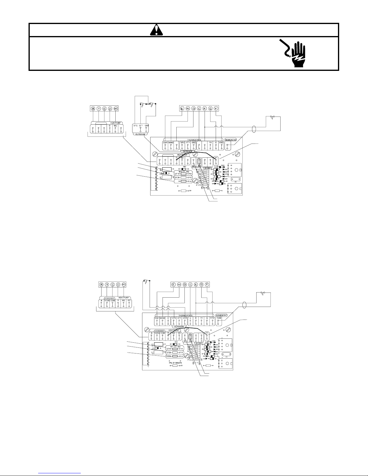
Heat Pump—2-Stage Emergency Heat and 2-Stage Auxiliary Heat—2 Outdoor Thermostats
Heat Pump
CONDEN SER
RYCON
ED
COM
CONDENSER
See Note 3
See Note 4
RYCONCOM
See Note 5
Please refer
to manual
for proper
1
DIP switch (CFM)
J
configuration.
NOTES:
■ No auxiliary heat in heat pump mode until outdoor thermostat
closes.
1. Y enables high speed fan cooling.
2. E enables low speed fan heating. W2 with OT1 closed
enables low speed fan heating. W2 with OT2 closed enables
high speed fan heating.
Room Thermostat
Humidistat
If Needed
(Optional)
See Note 5
ED
RC HUM
CR
TC
H
1SD
2nd Stage Heater
st
Stage Heater
1
Remove
Production
Wire Y1-O
5
1
3J
2
J
4
1
O
HUM
PN. B13682704
3. OT1 PJ4 must be cut for this configuration.
4. OT2 PJ2 must be cut for this configuration.
5. Cut HUM PJ6 jumper if using humidistat. Humidistat opens
on humidity rise.
6. DIP Switch 4 must be in the “ON” position.
Heat Pump—2-Stage Emergency Heat and 1-Stage Auxiliary Heat—1 Outdoor Thermostat
Heat Pump
See Note 3
See Note 4
See Note 5
NOTES:
1. Y enables high speed fan cooling.
2. E enables low speed fan heating. W2 with OT2 closed
enables high speed fan heating.
3. OT1 PJ4 must be cut for this configuration.
Outdoor Thermostat
Please refer
to manual
for proper
DIP switch (CFM)
configuration.
Room Thermostat
Humidistat
(Optional)
See Note 5
Remove
Production
Wire Y1-O
2nd Stage Heater
st
1
Stage Heater
4. OT2 PJ2 must be cut for this configuration.
5. Cut HUM PJ6 jumper if using humidistat. Humidistat opens
on humidity rise.
6. DIP Switch 4 must be in the “ON” position.
17
Page 18
WARNING
Disconnect ALL power before servicing.
Goodman 6 Long
HIGH VOLTAGE!
Multiple power sources may be present.
Failure to do so may cause property damage, personal injury or death.
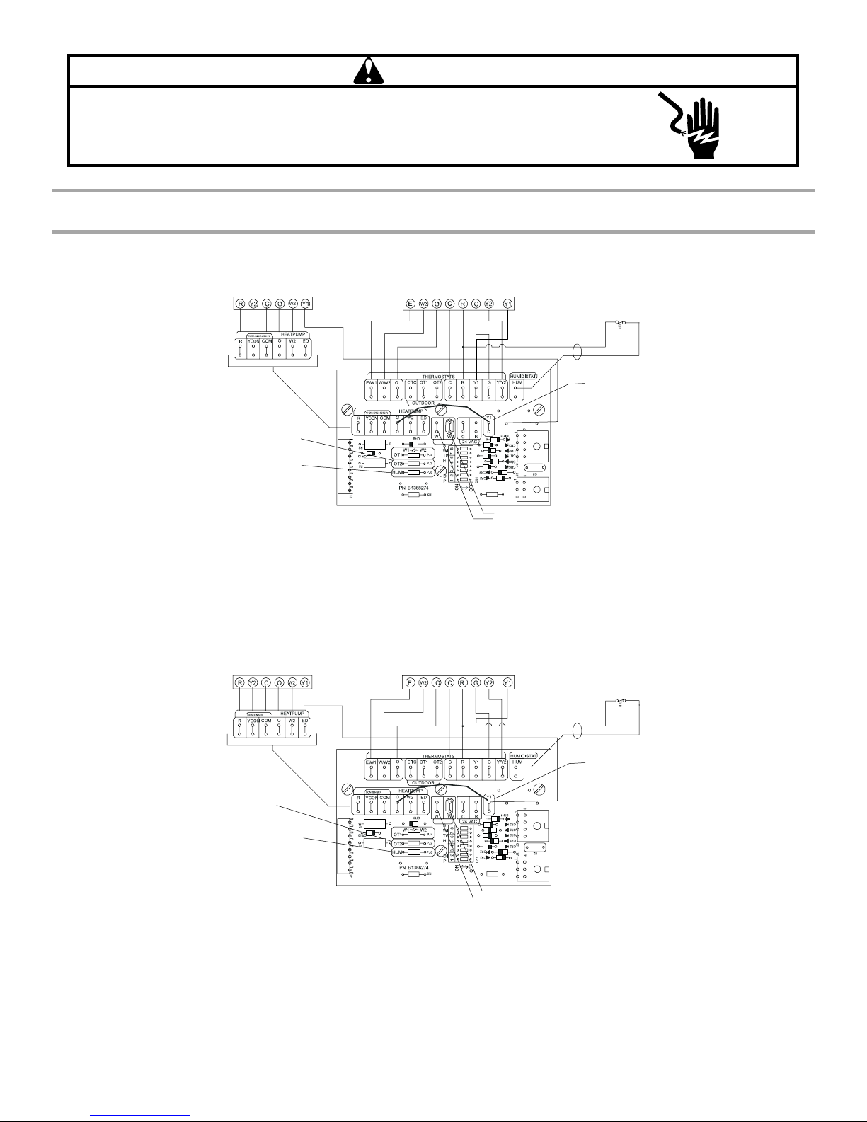
WMAHV 2-Speed Heat Pump with Single- or 2-Stage Heating and Options for Emergency Heat—Conventional
2-Stage Thermostat
Heat Pump—1-Stage Emergency Heat and 1-Stage Auxiliary Heat
2-Speed Heat Pump
See Note 3
See Note 4
Please refer
to manual
for proper
DIP switch (CFM)
configuration.
NOTES:
1. Y enables high speed fan cooling.
2. E enables low speed fan heating.
3. If OT2 PJ2 jumper is cut, E and W2 enable low speed fan
heating.
Room Thermostat
Humidistat
If Needed
nd
Stage Heater
2
st
1
Stage Heater
(Optional)
See Note 4
Remove
Production
Wire Y1-O
4. Cut HUM PJ6 jumper if using humidistat. Humidistat opens
on humidity rise.
5. DIP Switch 4 must be in the “OFF” position.
Heat Pump—2-Stage Emergency Heat and 1-Stage Auxiliary Heat
2-Speed Heat Pump
See Note 3
See Note 4
Please refer
to manual
for proper
DIP switch (CFM)
configuration.
NOTES:
1. Y enables high speed fan cooling.
2. E enables low speed fan heating. W2 enables high speed fan
heating.
3. OT2 PJ2 must be cut for this configuration.
Room Thermostat
If Needed
4. Cut HUM PJ6 jumper if using humidistat. Humidistat opens
5. DIP Switch 4 must be in the “OFF” position.
nd
2
Stage Heater
st
1
Stage Heater
on humidity rise.
Humidistat
(Optional)
See Note 4
Remove
Production
Wire Y1-O
18
Page 19
WARNING
Disconnect ALL power before servicing.
Goodman 6 Long
HIGH VOLTAGE!
Multiple power sources may be present.
Failure to do so may cause property damage, personal injury or death.
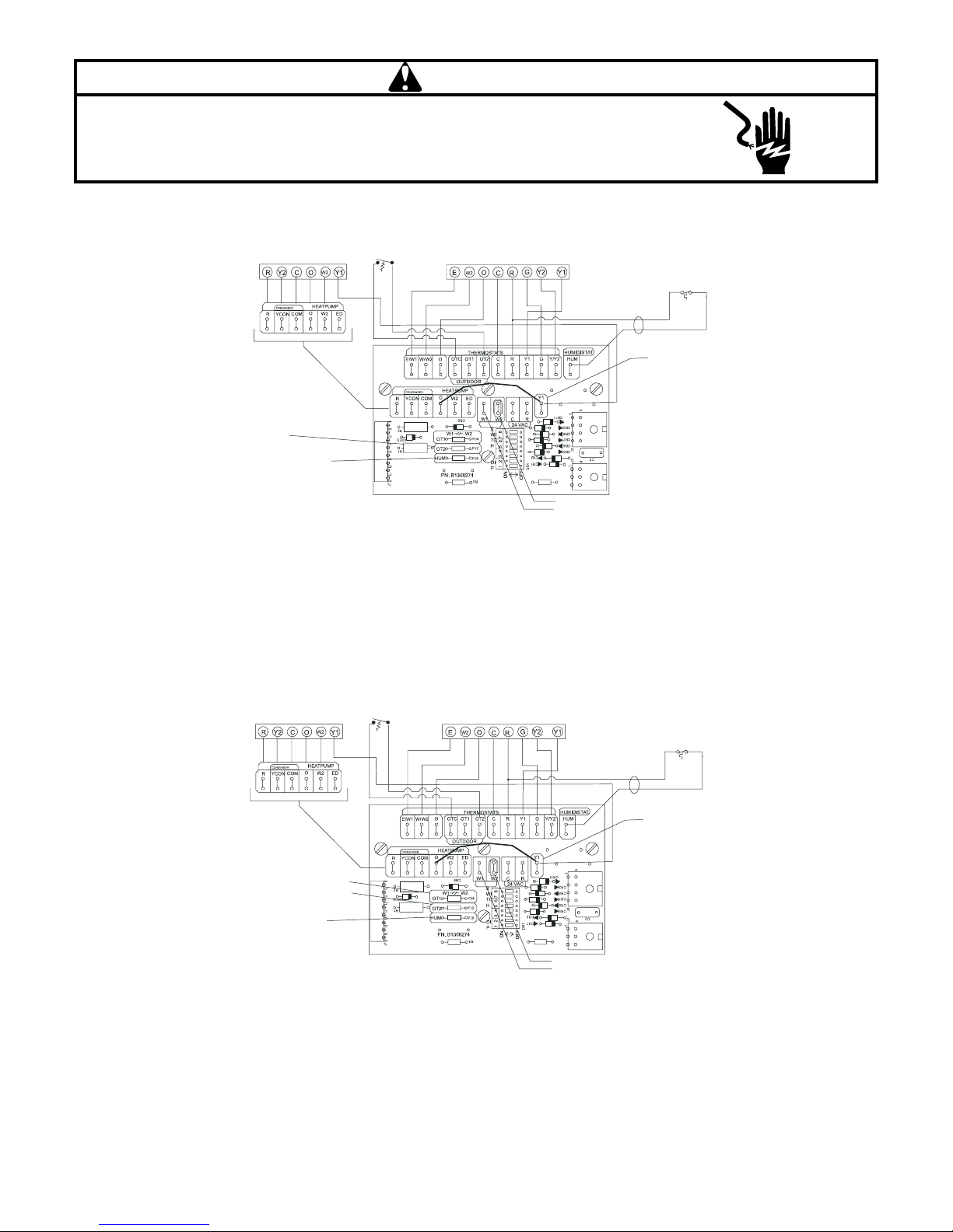
Heat Pump—2-Stage Emergency Heat and 2-Stage Auxiliary Heat—1 Outdoor Thermostat
2-Speed Heat Pump
See Note 3
See Note 4
NOTES:
st
■ 1
Stage auxiliary heat enabled by room thermostat.
nd
■ 2
Stage auxiliary heat enabled by room thermostat and
outdoor thermostat.
1. Y enables high speed fan cooling.
Outdoor Thermostat
Please refer
to manual
for proper
DIP switch (CFM)
configuration.
Room Thermostat
Humidistat
If Needed
nd
2
Stage Heater
st
1
Stage Heater
(Optional)
See Note 4
Remove
Production
Wire Y1-O
2. E enables low speed fan heating. W2 enables low speed fan
heating. W2 with OT2 closed enables high speed fan heating.
3. OT2 PJ2 must be cut for this configuration.
4. Cut HUM PJ6 jumper if using humidistat. Humidistat opens
on humidity rise.
5. DIP Switch 4 must be in the “OFF” position.
Heat Pump—2-Stage Emergency Heat and 1-Stage Auxiliary Heat—1 Outdoor Thermostat
See Note 3
See Note 4
Outdoor Thermostat
Please refer
to manual
for proper
DIP switch (CFM)
configuration.
Room Thermostat
Humidistat
If Needed
nd
2
Stage Heater
st
1
Stage Heater
(Optional)
See Note 5
Remove
Production
Wire Y1-O
3. OT1 PJ4 must be cut for this configuration.
4. OT2 PJ2 must be cut for this configuration.
5. Cut HUM PJ6 jumper if using humidistat. Humidistat opens
on humidity rise.
6. DIP Switch 4 must be in the “OFF” position.
2-Speed Heat Pump
See Note 5
NOTES:
■ No auxiliary heat in heat pump mode until outdoor thermostat
closes.
1. Y enables high speed fan cooling.
2. E enables low speed fan heating. W2 with OT2 closed
enables high speed fan heating.
19
Page 20
WARNING
Disconnect ALL power before servicing.
Goodman 6 Long
HIGH VOLTAGE!
Multiple power sources may be present.
Failure to do so may cause property damage, personal injury or death.
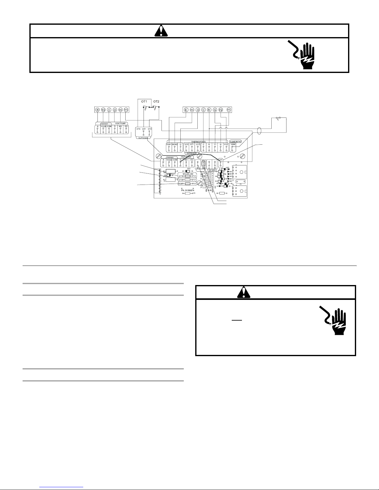
Heat Pump—2-Stage Emergency Heat and 2-Stage Auxiliary Heat—2 Outdoor Thermostats
2-Speed Heat Pump
See Note 3
See Note 4
See Note 5
Please refer
to manual
for proper
DIP switch (CFM)
configuration.
NOTES:
■ No auxiliary heat in heat pump mode until outdoor thermostat
closes.
1. Y enables high speed fan cooling.
2. E enables low speed fan heating. W2 with OT1 closed
enables low speed fan heating. W2 with OT2 closed enables
high speed fan heating.
Room Thermostat
Humidistat
If Needed
nd
2
Stage Heater
st
1
Stage Heater
(Optional)
See Note 5
Remove
Production
Wire Y1-O
3. OT1 PJ4 must be cut for this configuration.
4. OT2 PJ2 must be cut for this configuration.
5. Cut HUM PJ6 jumper if using humidistat. Humidistat opens
on humidity rise.
6. DIP Switch 4 must be in the “OFF” position.
Complete Installation
Pre-Start Check
■ Is the unit properly located, level, secure and serviceable?
■ Is the wiring neat, correct and in accordance with the wiring
diagram?
■ Is the unit properly grounded and connected to the correct
size fuse or circuit breaker?
■ Is the thermostat correctly wired, level, and in a good
location?
■ Are all of the access panels in place and secure?
■ Are all of the accessories properly installed?
Check Airflow (WMAHV Motor)
For proper cooling operation, the airflow through the indoor coil
should be between 350 and 450 CFM per ton of cooling capacity
(or 350 to 450 CFM per 12,000 Btu/h) based on the rating of the
outdoor condensing unit.
WARNING
HIGH VOLTAGE!
Disconnect ALL power before servicing.
Multiple power sources may be present.
Failure to do so may cause property damage,
personal injury or death.
The WMAHV control board is factory set with DIP Switch #4 in
the “ON” position and all other DIP switches are factory set in the
“OFF” position. For most applications, the settings are to be
changed according to the electric heat size and the outdoor unit
selection.
The WMAHV motor provides many features not available on the
traditional PSC motor. These features include:
■ Improved efficiency
■ Constant CFM
■ Soft start and stop
■ Improved humidity control
Goodman 6
20
Page 21

Motor Speed Adjustment
Each WMAHV blower motor has been preprogrammed for
operation at 4 distinct airflow levels when operating in cooling/
heat pump mode or electric heat mode. These 4 distinct levels
may also be adjusted slightly lower or higher if desired.
The adjustment between levels and the trim adjustments are
made by changing the DIP switch(s) either to an OFF or ON
position.
DIP Switch Number Function
1
Electric Heat
2
3N/A
4 Indoor Thermostat
DIP Switch Functions
The WMAHV blower motor has an electronic control that contains
an 8-position DIP switch. The functions of these DIP switches are
shown in the following chart.
5
Cooling/Heat Pump CFM
6
7
CFM Trim Adjust
8
CFM Delivery
The following table shows the CFM output for DIP switch combinations 1 and 2, and for 5 and 6.
Model Switch 1 Switch 2 Electric Heat CFM Switch 5 Switch 6 Cooling/Heat Pump CFM
WMAHV 1200 Off Off 1,200 Off Off 1,200
On Off 1,000 On Off 1,000
Off On 800 Off On 800
On On 600 On On 600
WMAHV 1600 Off Off 1,600 Off Off 1,600
On Off 1,400 On Off 1,400
Off On 1,200 Off On 1,200
On On 1,000 On On 1,000
WMAHV 2000 Off Off 1,900 Off Off 2,000
On Off 1,600 On Off 1,800
Off On 1,400 Off On 1,600
On On 1,200 On On 1,200
Thermostat—Fan Only Mode
During Fan Only Operations, the CFM output is 30% of the
cooling setting.
Humidity Control
When using a humidistat (normally closed), cut jumper PJ6 on the
control board. The humidistat will only affect the cooling airflow
by adjusting the airflow to 85%.
CFM Trim Adjustment
Minor adjustments can be made through the DIP switch
combination of 7 and 8. The following table shows the DIP switch
position for this feature.
NOTE: The airflow will not make the decreasing adjustment in
Electric Heat mode.
2-Stage Heating
When using staged electric heat, cut jumper PJ4 on the control
board.
CFM Switch 7 Switch 8
+10% On Off
-15% Off On
NOTE: If no adjustment is required, DIP switches 7 and 8 should
be left in the OFF position.
21
Page 22

Check Airflow (WMAHM Motor)
For proper cooling operation, the airflow through the indoor coil should be between 350 and 450 CFM per ton of cooling capacity
(or 350 to 450 CFM per 12,000 Btu/h) based on the rating of the outdoor condensing unit.
Speed Static WMAHM0800**-*SCFM WMAHM1200**-*SCFM WMAHM1600**-*SCFM WMAHM2000**-*SCFM
High 0.1 1,240 1,500 1,800 2,160
0.2 1,170 1,460 1,740 2,080
0.3 1,120 1,360 1,680 1,990
0.4 1,060 1,280 1,610 1,890
0.5 980 1,200 1,520 1,790
0.6 900 1,110 1,430 1,690
Medium 0.1 900 1,380 1,540 1,730
0.2 850 1,320 1,490 1,670
0.3 790 1,270 1,450 1,590
0.4 740 1,200 1,400 1,520
0.5 680 1,140 1,350 1,420
0.6 605 1,040 1,280 1,320
Low 0.1 650 1,170 1,130 1,520
0.2 590 1,130 1,100 1,450
0.3 540 1,080 1,070 1,360
0.4 500 1,020 1,030 1,290
0.5 430 950 990 1,200
0.6 330 830 930 1,090
22
Page 23
SEQUENCE OF OPERATION
Cooling—Cooling Only or Heat Pump
When the thermostat calls for cooling, the circuit between R and
G is completed, and the blower relay is energized. The normally
open contacts close, causing the indoor blower motor to operate.
The circuit between R and Y is also completed; this circuit closes
the contactor in the outdoor unit starting the compressor and
outdoor fan motor. Circuit R and O energizes the reversing valve,
switching it to the cooling position. (The reversing valve remains
energized as long as selector switch is in the COOL position.)
Heating—Electric Heat Only
When the thermostat calls for heat, the circuit between R and W
is completed, and the heat sequencer relay is energized. A time
delay follows before the heating elements and the indoor blower
motor come on. Units with a second heat sequencer relay can be
connected with the first sequencer to W on the thermostat
subbase or connected to a 2
nd
stage on the subbase.
AIR HANDLER MAINTENANCE
WARNING
HIGH VOLTAGE!
Disconnect ALL power before servicing.
Multiple power sources may be present.
Failure to do so may cause property damage,
personal injury or death.
IMPORTANT: Do not operate system without a filter. A filter is
required to keep excessive dirt and dust from the coil, blower,
and internal parts. The filter is placed in the supply air return duct
by the installer.
Goodman 6
Heating—Heat Pump
When the thermostat calls for heat, the circuits between R and Y
and R and G are completed. Circuit R-Y energizes the contactor
starting the outdoor fan motor and the compressor. Circuit R
and G energizes the blower relay starting the indoor blower
motor.
If the room temperature should continue to fall, the circuit
between R and W1 is completed by the 2
thermostat. Circuit R-W1 energizes a heat sequencer relay. The
completed circuit will energize supplemental electric heat (if
available). Units with a second heat sequencer relay can be
connected with the first sequencer to W1 on the thermostat or
connected to a second heating stage W2 on the thermostat
subbase.
■ Inspect air filters at least once a month and replace or clean
as required. Dirty filters are the most common cause of
inadequate heating or cooling performance.
■ Replace disposable filters. Cleanable filters can be cleaned
by soaking in mild detergent and rinsing with cold water.
■ Install new/clean filters with the arrows on the side pointing in
the direction of airflow.
■ Do not replace a cleanable (high velocity) filter with a
disposable (low velocity) filter unless the return air system is
properly sized for it.
■ If water should start coming from the secondary drain line, a
problem exists which should be investigated and corrected.
Contact a qualified person.
nd
stage heat room
ASSISTANCE OR SERVICE
If you need further assistance, you can write to the below
address with any questions or concerns:
Whirlpool
14610 Breakers Drive
Jacksonville, FL 32258
Please include a daytime phone number in your correspondence.
®
Home Cooling and Heating
Accessories
To order accessories, contact your Whirlpool© Home Cooling and
Heating dealer.
Electric Heat Kits
Refer to the accessory kit label on the front panel of the air
handler for electric heat kit accessory options and applications.
23
Page 24

W
PIO-239E
©
2009. All rights reserved.
Manufactured under license by Tradewinds Distributing Company, LLC., Jacksonville, Florida
®Registered Trademark/TM Trademark of Whirlpool, U.S.A.,
Printed in U.S.A.
8/09
 Loading...