

Page 1
HYBRIDCARE™ HEAT
SÉCHEUSE À POMPE À
PUMP DRYER
INSTALLATION
INSTRUCTIONS
Table of Contents
DRYER SAFETY .........................................................................2
INSTALLATION REQUIREMENTS ............................................. 3
Tools and Parts ...................................................................... 3
LOCATION REQUIREMENTS .................................................... 4
DRAIN SYSTEM ......................................................................... 5
ELECTRICAL REQUIREMENTS – U.S.A. ONLY ....................... 6
ELECTRIC DRYER POWER HOOKUP – CANADA ONLY ........ 7
INSTALL LEVELING LEGS ......................................................... 8
ELECTRICAL INSTALLATION – U.S.A. ONLY ..........................8
Power Supply Cord Connection ........................................... 9
Direct Wire Connection ....................................................... 11
CONNECT OUTLET HOSE ...................................................... 14
LEVEL DRYER .......................................................................... 15
COMPLETE INSTALLATION CHECKLIST ..............................16
DOOR REVERSAL (OPTIONAL) .............................................. 16
TROUBLESHOOTING .............................................................. 20
CHALEUR HYBRIDCARE™
INSTRUCTIONS
D’INSTALLATION
Table des matières
SÉCURITÉ DE LA SÉCHEUSE ................................................ 21
EXIGENCES D’INSTALLATION ...............................................22
Outillage et pièces ............................................................... 22
EXIGENCES D’EMPLACEMENT ............................................. 23
SYSTÈME DE VIDANGE .......................................................... 24
SÉCHEUSE ÉLECTRIQUE RACCORDEMENT
À L’ALIMENTATION ÉLECTRIQUE –
CANADA SEULEMENT ............................................................ 25
INSTALLATION DES PIEDS DE NIVELLEMENT .................... 26
CONNEXION DU TUYAU DE SORTIE ..................................... 26
RÉGLAGE DE L’APLOMB DE LA SÉCHEUSE........................27
ACHEVER L’INSTALLATION LISTE DE VÉRIFICATION ......... 28
INVERSION DE LA PORTE (FACULTATIF) .............................. 28
DÉPANNAGE ......................................COUVERTURE ARRIÈRE
Para una version de estas instrucciones en español, visite www.Whirlpool.com o www.maytag.com
INSTALLATION NOTES
Date of purchase: _________________________________
Date of installation: _______________________________
Installer: ________________________________________
Model number: ___________________________________
Serial number: ___________________________________
NOTES CONCERNANT L’INSTALLATION
Date d’achat : _____________________________________
Date d’installation : ________________________________
Installateur : ______________________________________
Numéro de modèle : ________________________________
Numéro de série : __________________________________
W11184511A
W11184519A - SP
Page 2

DRYER SAFETY
Certain internal parts are intentionally not grounded and may present a risk of electric shock
only during servicing.
Service Personnel – Do not contact the thermostat bracket while the appliance is energized.
2
Page 3

INSTALLATION REQUIREMENTS
TOOLS AND PARTS
Gather the required tools and parts before starting installation.
Tools needed:
Flat-blade screwdriver #2 Phillips screwdriver
Wire stripper (direct wire
installations)
1/4" and 5/16" nut driver
(recommended)
Channel locks
Adjustable wrench that
opens to 1" (25 mm) or
hex-head socket wrench
Parts supplied:
Leveling legs (4)
Cable ties (2)
Parts package is located in dryer drum. Check that all parts
are included.
NOTE: Do not use leveling legs supplied with dryer if installing
with a pedestal or a stack kit.
6' (1.82 m) drain
hose with couplers
If using a power supply cord:
Use a UL Listed power supply cord kit marked for use with
clothes dryers. The kit should contain:
■ A UL Listed 30 A power supply cord, rated 120/240 V
minimum. The cord should be type SRD or SRDT and
be at least 4 ft. (1.22 m) long. The wires that connect to
the dryer must end in ring terminals or spade terminals
with upturned ends.
■ A UL Listed strain relief.
Additional Accessories: (Not supplied with dryer)
Refer to your Use and Care Guide for information about
accessories available for your dryer.
Utility knife Tape measure
Level
Pliers
3
Page 4

LOCATION REQUIREMENTS
Check codes requirements. Some codes limit, or do not permit,
installing dryer in garages, closets, mobile homes, or sleeping
quarters. Contact your local building inspector.
You will need:
■ A separate 30 A circuit.
■ If using a power supply cord, a grounded electrical outlet
located within 2 ft. (610 mm) of either side of dryer. See
“Electrical Requirements.”
■ Floor must support dryer weight of 200 lbs. (90.7 kg). Also
consider weight of companion appliance.
■ Level oor with maximum slope of 1" (25 mm) under entire
dryer. If forward slope is greater than 1" (25 mm), water could
run out from front of lter. Install Extended Dryer Feet Kit, Part
Number 279810. If not level, clothes may not tumble properly
and automatic sensor cycles may not operate correctly.
■ For garage installation, place dryer at least 18" (460 mm)
above oor. If using a pedestal, you will need 18" (460 mm)
to bottom of dryer.
■ The dryer must not be installed or stored in an area where it
will be exposed to water and/or weather.
IMPORTANT: Do not operate, install, or store dryer where
it will be exposed to water, weather, or at temperatures below
40°F (4°C). Lower temperatures may cause dryer to not
shut off at end of automatic sensor cycles, resulting in longer
drying times.
DRYER DIMENSIONS
Front view:
27"
(686 mm)
Side view:
541/2"
51 " min.
(1378 mm)
(1314 mm)
31"
31 " min.
(787 mm)
(806 mm)
53/4"
(146 mm)
Back view:
61/2"
(165 mm)
NOTE: Allow
clearance behind
dryer for proper
drain hose routing
and cooling fan
ventilation. Push
dryer back as
far as possible
and make sure
drain hose is not
crushed or kinked.
*Approx. measurement
Power cord/
cable
Water
Cooling
drain
131/2"
(343 mm)
fan
29
(759 mm)
1
/2"
6
(165 mm)
7
/8"*
IMPORTANT: Do not block cooling fan, as your dryer may not
operate properly.
383/4" Min.
(984 mm)
39" Max.
(990 mm)
4
Page 5

Installation spacing for recessed area or closet
installation:
All dimensions show recommended and minimum spacing allowed.
■ Additional spacing should be considered for ease of
installation and servicing.
■ Additional clearances might be required for wall, door, oor,
moldings, and drain system.
■ Additional spacing should be considered on all sides of the dryer
to reduce noise transfer.
■ For closet installation, with a door, minimum ventilation openings
in the top and bottom of the door are required. Louvered doors
with equivalent ventilation openings are acceptable.
■ Companion appliance spacing should also be considered.
Recommended installation clearances (dryer only):
3"
18" min.
(457 mm)
(76 mm)
48 in.2 min.
(310 cm
2
)
DRAIN SYSTEM
Drain system can be installed using a oor drain, wall standpipe,
oor standpipe, or laundry tub. Select method you need.
IMPORTANT: To avoid siphoning, only 4.5" (114 mm) of drain
hose should be inside standpipe. Always secure drain hose with
cable tie.
Floor standpipe drain system
4.5"
4.5"
(114 mm)
(114 mm)
4.5"
4.5"
(114 mm)
(114 mm)
max. 54"
(1372 mm)
min. 30"
(762 mm)
Without pedestal
max. 69"
(1753 mm)
min. 30"
(762 mm)
0" – 5"*
(0 mm – 127 mm)
5"
(127 mm)
1"
(25 mm)
(76 mm)
1"
(25 mm)
3"
24 in.2 min.
(155 cm2)
*NOTE: 0" (0 mm)
spacing is allowed
behind dryer, providing
drain hose is not kinked
or pinched.
Mobile home – Additional installation requirements:
This dryer is suitable for mobile home installations. The
installation must conform to the Manufactured Home
Construction and Safety Standard, Title 24 CFR,
Part 3280 (formerly the Federal Standard for Mobile
home construction and Safety, Title 24, HUD Part 280)
or Standard CAN/CSA-Z240 MH.
With 15" (381 mm) matching pedestal
Minimum diameter for a standpipe drain: 2" (51 mm). Minimum
carry-away capacity: 17 gal. (64 L) per minute. A 1/4" (6 mm)
diameter to 1" (25 mm) diameter Standpipe Adapter Kit is
available. Top of standpipe must be at least 30" (762 mm) high;
install no higher than 54" (1.37 m) from bottom of dryer.
IMPORTANT: Only 4.5" (114 mm) of drain hose should be inside
standpipe; do not force excess hose into standpipe.
Wall standpipe drain system
4.5"
(114 mm)
See requirements for oor standpipe drain system.
5
Page 6

Laundry tub drain system
4.5"
4.5"
(114 mm)
(114 mm)
max. 54"
(1372 mm)
min. 30"
(762 mm)
Minimum capacity: 20 gal. (76 L). Top of laundry tub must
be at least 30" (762 mm) above oor; install no higher than
54" (1.37 m) from bottom of dryer.
IMPORTANT: Only 4.5" (114 mm) of drain hose should lay
on side of laundry tub. Do not lay the hose at the bottom of tub.
Floor drain system
Remove the U-bend at the end of the drain hose by cutting
the hose at the end of the U-bend for the oor drain system
as shown in the picture above.
NOTE: Cut hose so that no more than 4.5" (114 mm) of the hose
is in the oor drain to avoid siphoning.
Electrical Connection
To properly install your dryer, you must determine the type of
electrical connection you will be using and follow the instructions
provided for it here.
■ This dryer is manufactured ready to install with a 3-wire
electrical supply connection. The neutral ground conductor
is permanently connected to the neutral conductor (white wire)
within the dryer. If the dryer is installed with a 4-wire electrical
supply connection, the neutral ground conductor must be
removed from the external ground connector (green screw),
and secured under the neutral terminal (center or white wire)
of the terminal block. When the neutral ground conductor is
secured under the neutral terminal (center or white wire) of the
terminal block, the dryer cabinet is isolated from the neutral
conductor. The green ground wire of the 4-wire power cord
must be secured to the dryer cabinet with the green
ground screw.
■ If local codes do not permit the connection of a neutral
ground wire to the neutral wire, see the “Optional External
Ground for 3-Wire Connection” section.
■ A 4-wire power supply connection must be used when the
appliance is installed in a location where grounding through
the neutral conductor is prohibited. Grounding through the
neutral is prohibited for (1) new branch-circuit installations after
1996, (2) mobile homes, (3) recreational vehicles, and (4) areas
where local codes prohibit grounding through the neutral
conductors.
If using a power supply cord:
Use a UL Listed power supply cord kit marked for use with
clothes dryers. The kit should contain:
■ A UL Listed 30 A power supply cord, rated 120/240 V
minimum. The cord should be type SRD or SRDT and
be at least 4 ft. (1.22 m) long. The wires that connect to
the dryer must end in ring terminals or spade terminals
with upturned ends.
■ A UL Listed strain relief.
ELECTRICAL REQUIREMENTS –
U.S.A. ONLY
It is your responsibility:
■ To contact a qualied electrical installer.
■ To be sure that the electrical connection is adequate and
in conformance with the National Electrical Code, ANSI/
NFPA 70 – latest edition and all local codes and ordinances.
The National Electrical Code requires a 4-wire power supply
connection for homes built after 1996, dryer circuits involved
in remodeling after 1996, and all mobile home installations.
A copy of the above code standards can be obtained from:
National Fire Protection Association, One Batterymarch Park,
Quincy, MA 02269.
■ To supply the required 3- or 4-wire, single-phase, 120/240 V,
60 Hz, AC-only electrical supply (or 3- or 4-wire, 120/208 V
electrical supply, if specied on the serial/rating plate) on a
separate 30 A circuit, fused on both sides of the line. Connect
to an individual branch circuit. Do not have a fuse in the neutral
or grounding circuit.
■ Do not use an extension cord.
■ If codes permit and a separate ground wire is used, it is
recommended that a qualied electrician determine that
the ground path is adequate.
If your outlet looks like this:
Then choose a 4-wire power supply cord with
ring or spade terminals and UL Listed strain
relief. The 4-wire power supply cord, at least
4 ft. (1.22 m) long, must have four 10-gauge
copper wires and match a 4-wire receptacle of
NEMA Type 14-30R. The ground wire (ground
4-wire receptacle
(14-30R)
3-wire receptacle
(10-30R)
conductor) may be either green or bare. The
neutral conductor must be identied by a white
cover.
Then choose a 3-wire power supply cord with
ring or spade terminals and UL Listed strain
relief. The 3-wire power supply cord, at least
4 ft. (1.22 m) long, must have three 10-gauge
copper wires and match a 3-wire receptacle
of NEMA Type 10-30R.
If connecting by direct wire:
Power supply cable must match power supply (4-wire or 3-wire)
and be:
■ Flexible armored cable or nonmetallic sheathed copper cable
(with ground wire), covered with exible metallic conduit.
All current-carrying wires must be insulated.
■ 10-gauge solid copper wire (do not use aluminum) at least
5 ft. (1.52 m) long.
6
Page 7
ELECTRIC DRYER POWER
HOOKUP – CANADA ONLY
■ To supply the required 4-wire, single-phase, 120/240 V,
60 Hz., AC-only electrical supply on a separate 30 amp circuit,
fused on both sides of the line. A time-delay fuse or circuit
breaker is recommended. Connect to an individual branch
circuit.
■ This dryer is equipped with a CSA International Certied
Power Cord intended to be plugged into a standard 14-30R
wall receptacle. The cord is 5 ft. (1.52 m) in length. Be sure
wall receptacle is within reach of dryer’s nal location.
4-wire receptacle (14-30R)
■ Do not use an extension cord.
If using a replacement power supply cord, it is recommended that
you use Power Supply Cord Replacement Part Number 8579325.
For further information, please reference the “Assistance or
Service” section of the Use and Care Guide.
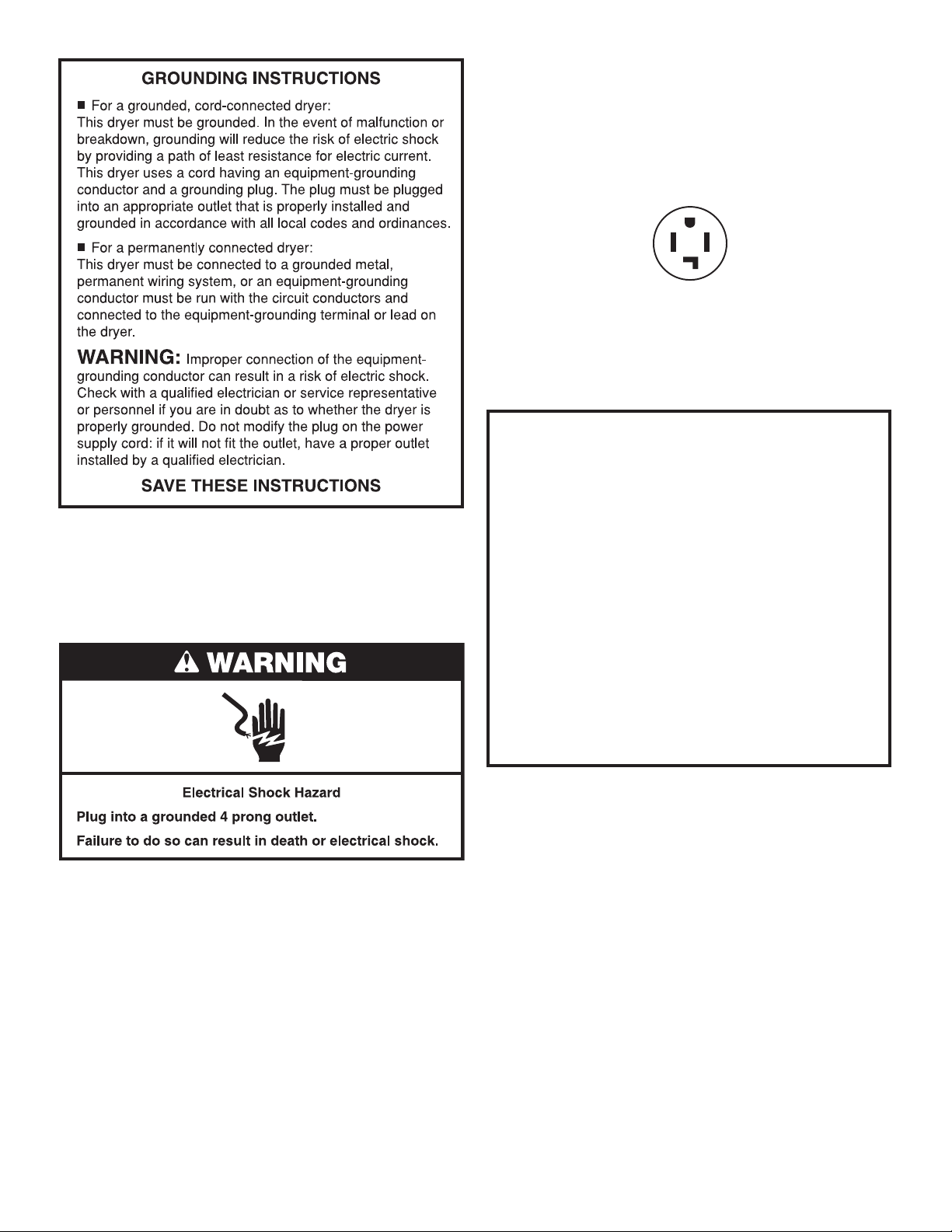
GROUNDING INSTRUCTIONS
■
For a grounded, cord-connected dryer:
This dryer must be grounded. In the event of malfunction or
breakdown, grounding will reduce the risk of electric shock
by providing a path of least resistance for electric current.
This dryer is equipped with a cord having an equipmentgrounding conductor and a grounding plug. The plug must
be plugged into an appropriate outlet that is properly
installed and grounded in accordance with all local codes
and ordinances.
ELECTRICAL REQUIREMENTS
It is your responsibility:
■ To contact a qualied electrical installer.
■ To be sure that the electrical connection is adequate
and in conformance with the Canadian Electrical Code,
C22.1-latest edition, and all local codes. A copy of the
above codes standard may be obtained from: Canadian
Standards Association, 178 Rexdale Blvd., Toronto, ON
M9W 1R3 CANADA.
WARNING: Improper connection of the equipment-
grounding conductor can result in a risk of electric shock.
Check with a qualied electrician or service representative
or personnel if you are in doubt as to whether the dryer is
properly grounded. Do not modify the plug provided with
the dryer: if it will not t the outlet, have a proper outlet
installed by a qualied electrician.
SAVE THESE INSTRUCTIONS
7
Page 8
INSTALL LEVELING LEGS
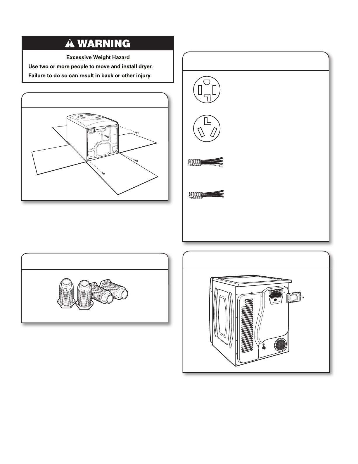
1. Prepare dryer for leveling legs
ELECTRICAL INSTALLATION –
U.S.A. ONLY
Before you start, disconnect power.
1. Choose electrical connection type
Power supply cord 4-wire receptacle
(NEMA Type 14-30R).
Go to “Power Supply Cord Connection.”
Power supply cord 3-wire receptacle
(NEMA Type 10-30R).
Go to “Power Supply Cord Connection.”
4-wire direct connection:
Go to “Direct Wire Connection.”
3-wire direct connection:
Go to “Direct Wire Connection.”
To avoid damaging oor, use a large at piece of cardboard
from dryer carton; place under entire back edge of dryer.
Firmly grasp dryer body (not console panel) and gently lay
dryer down on cardboard.
NOTE: Residual water from factory testing may drain when
dryer is laying on its side.
2. Screw in leveling legs
Using a wrench and tape measure, screw leveling legs into
leg holes until bottom of foot is approximately 1/2" (13 mm)
from bottom of dryer.
Now stand the dryer on its feet. Slide the dryer until it is
close to its nal location.
NOTE: If local codes do not permit connection of a
cabinet-ground conductor to neutral wire, go to “Optional
External Ground for 3-Wire Connection.” This connection
may be used with either a power supply cord or a direct
wire connection.
2. Remove terminal block cover
Remove hold-down screw and terminal block cover.
8
Page 9
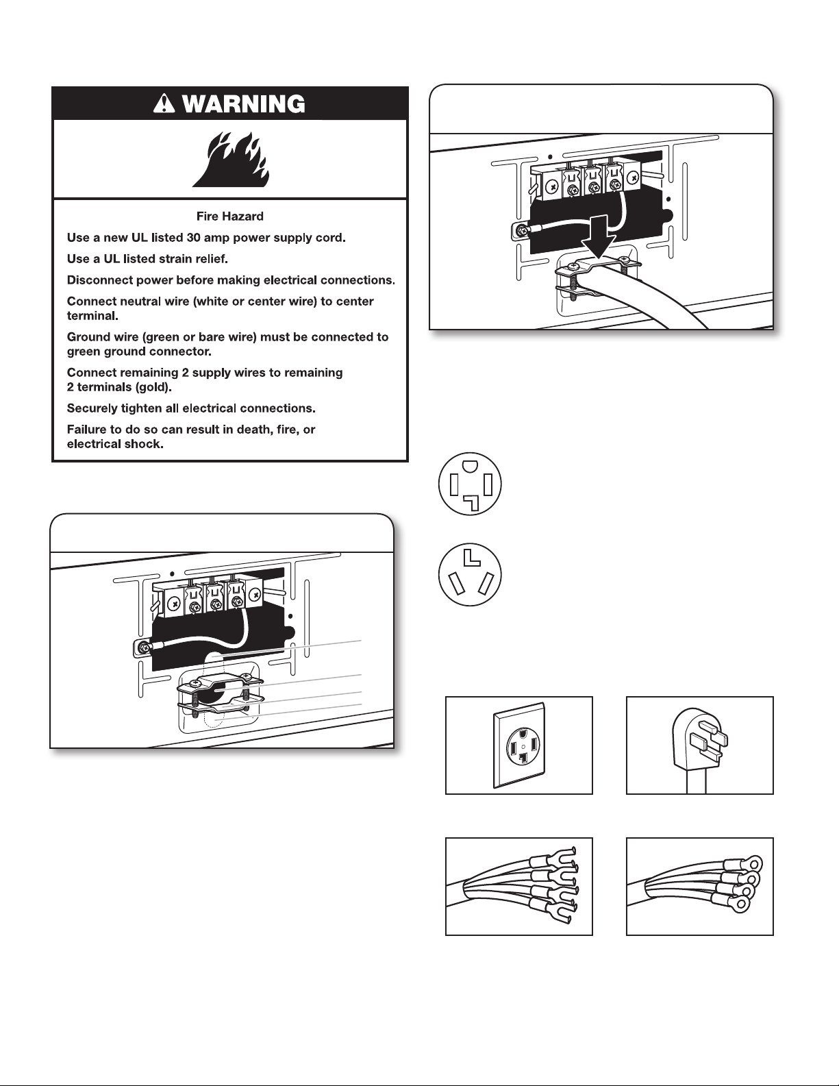
Power Supply Cord Connection
Power Supply Cord Strain Relief:
2. Attach power supply cord
to strain relief
Put power supply cord through the strain relief. Be sure that
the wire insulation on the power supply cord is inside the
strain relief. The strain relief should have a tight t with the
dryer cabinet and be in a horizontal position. Do not further
tighten strain relief screws at this point.
If your outlet looks like this:
Power supply cord 4-wire receptacle
(NEMA Type 14-30R):
Go to “4-Wire Power Supply Cord
Connection.”
1. Attach power supply cord strain relief
A
B
C
D
Remove the screws from a 3/4" (19 mm) UL Listed strain
relief (UL marking on strain relief). Put the tabs of the two
clamp sections (C) into the hole below the terminal block
opening (B) so that one tab is pointing up (A) and the other
is pointing down (D), and hold in place. Tighten strain relief
screws just enough to hold the two clamp sections (C)
together.
Power supply cord 3-wire receptacle
(NEMA Type 10-30R):
Go to “3-Wire Power Supply Cord
Connection.”
4-Wire Power Supply Cord Connection
IMPORTANT: A 4-wire connection is required for mobile homes
and where local codes do not permit the use of 3-wire connections.
4-wire receptacle
(NEMA type 14-30R)
4 prong plug
Spade terminals with
upturned ends
Ring terminals
9
Page 10
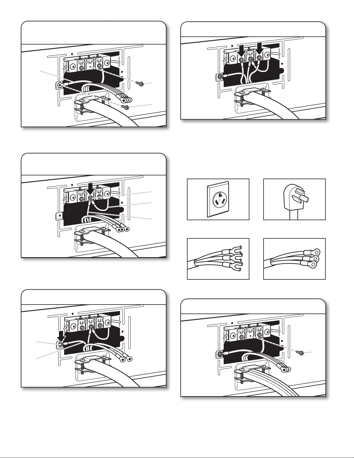
1. Prepare to connect neutral ground
wire and neutral wire
E
B
A
Remove center terminal block screw (B). Remove neutral
ground wire (E) from green external ground conductor screw (A).
4. Connect remaining wires
Connect remaining wires under outer terminal block screws.
Tighten screws. Finally, reinsert tab of terminal block cover
into slot of dryer rear panel. Secure cover with hold-down
screw. Now, go to “Connect Outlet Hose.”
2. Connect neutral ground wire and
neutral wire
B
E
C
Connect neutral ground wire (E) and neutral wire (white or
center) (C) of power supply cord under center terminal block
screw (B). Tighten screw.
3. Connect ground wire
3-Wire Power Supply Cord Connection
Use where local codes permit connecting cabinet-ground
conductor to neutral wire.
3-wire receptacle
(NEMA type 10-30R)
Spade terminals with
upturned ends
3 prong plug
Ring terminals
1. Remove center screw
A
F
Connect ground wire (F) (green or bare) of power supply cord
under green external ground conductor screw (A). Tighten
screw.
10
B
Remove center terminal block screw (B).
Page 11
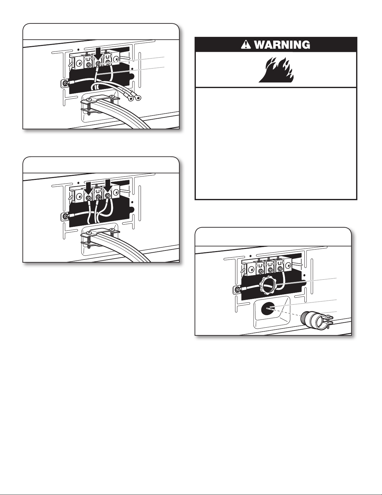
2. Connect neutral wire
B
C
Connect neutral wire (white or center) (C) of power supply cord
under center terminal block screw (B). Tighten screw.
3. Connect remaining wires
Direct Wire Connection
Fire Hazard
Use 10 gauge copper wire.
Use a UL listed strain relief.
Disconnect power before making electrical connections.
Connect neutral wire (white or center wire) to center
terminal.
Ground wire (green or bare wire) must be connected
to green ground connector.
Connect remaining 2 supply wires to remaining
2 terminals (gold).
Securely tighten all electrical connections.
Failure to do so can result in death, re, or
electrical shock.
Connect remaining wires under outer terminal block screws.
Tighten screws. Finally, reinsert tab of terminal block cover
into slot of dryer rear panel. Secure cover with hold-down
screw. Now, go to “Connect Outlet Hose.”
Direct wire strain relief
1. Attach direct wire strain relief
A
B
C
Unscrew the removable conduit connector (A) and any
screws from a 3/4" (19 mm) UL Listed strain relief (UL marking
on strain relief). Put the threaded section of the strain relief
(C) through the hole below the terminal block opening (B).
Reaching inside the terminal block opening, screw the
removable conduit connector (A) onto the strain relief threads,
and tighten securely.
11
Page 12
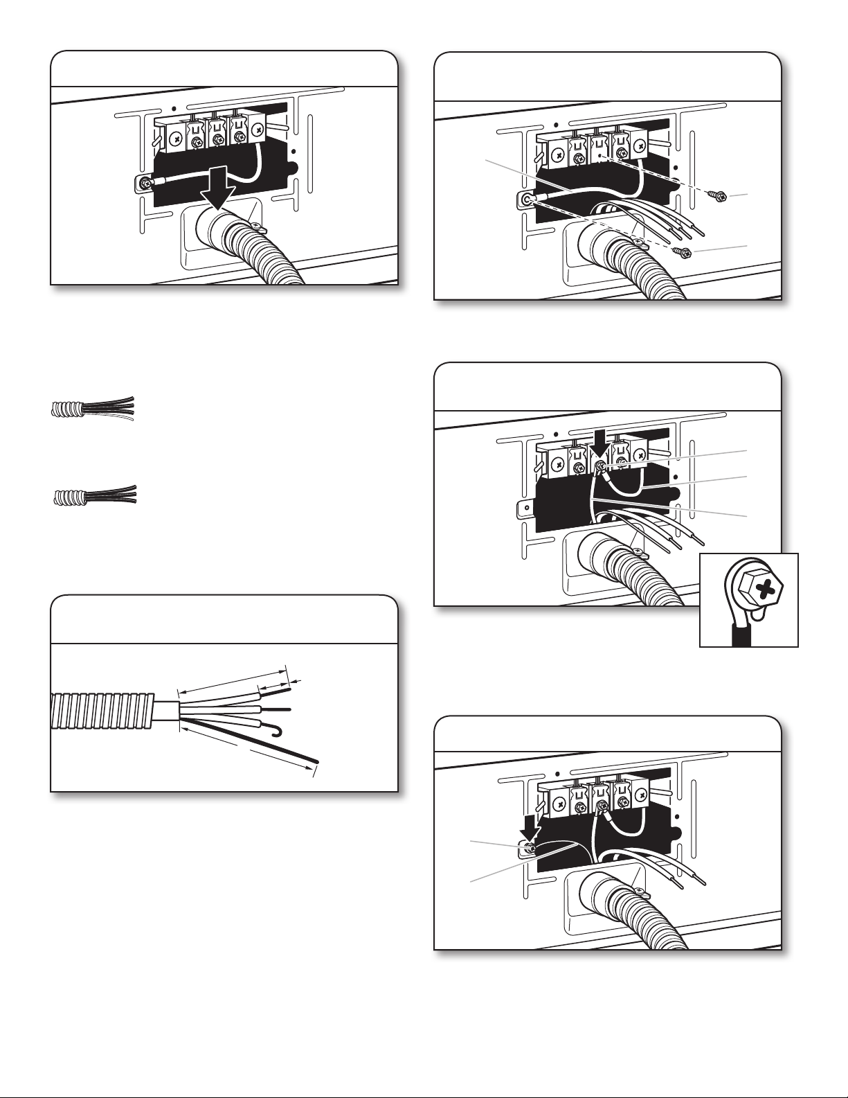
2. Attach direct wire cable to strain relief
Put direct wire cable through the strain relief. The strain
relief should have a tight t with the dryer cabinet and be in
a horizontal position. Tighten strain relief screw against the
direct wire cable.
If your wiring looks like this:
4-wire direct connection:
Go to “4-Wire Direct Wire Connection.”
2. Prepare to connect neutral ground
wire and neutral wire
E
B
A
Remove center terminal block screw (B). Remove neutral
ground wire (E) from green external ground conductor screw (A).
3. Connect neutral ground wire and
neutral wire
B
3-wire direct connection:
Go to “3-Wire Direct Wire Connection.”
4-Wire Direct Wire Connection
IMPORTANT: A 4-wire connection is required for mobile homes
and where local codes do not permit 3-wire connections.
1. Prepare your 4-wire cable
for direct connection
1
"
2
⁄
3
(89 mm)
5"
(127 mm)
Direct wire cable must have 5 ft. (1.52 m) of extra length so
dryer may be moved if needed.
Strip 5" (127 mm) of outer covering from end of cable,
leaving bare ground wire at 5" (127 mm). Cut 11/2" (38 mm)
from remaining 3 wires. Strip insulation back 1" (25 mm).
Shape ends of wires into hooks.
1"
(25 mm)
E
C
Connect neutral ground wire (E) and place
hooked end (hook facing right) of neutral wire
(white or center wire) (C) of direct wire cable
under center screw of terminal block (B).
Squeeze hooked ends together and tighten screw.
4. Connect ground wire
A
F
12
Connect ground wire (green or bare) (F) of direct wire cable
under green external ground conductor screw (A). Tighten
screw.
Page 13
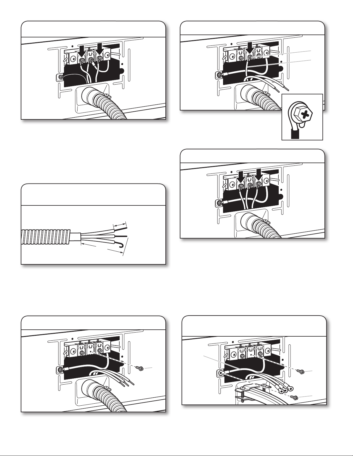
5. Connect remaining wires
Place hooked ends of remaining direct wire cable wires under
outer terminal block screws (hooks facing right). Squeeze
hooked ends together and tighten screws. Finally, reinsert tab of
terminal block cover into slot of dryer rear panel. Secure
with hold-down screw. Now, go to “
Connect Outlet Hose.
cover
”
3-Wire Direct Wire Connection
Use where local codes permit connecting cabinet-ground
conductor to neutral wire.
1. Prepare your 3-wire cable
for direct connection
3. Connect neutral wire
B
C
Place hooked end of neutral wire (white
or center) (C) of direct wire cable under
center terminal block screw (B), hook
facing right. Squeeze hooked end
together. Tighten screw.
4. Connect remaining wires
1"
(25 mm)
3½"
(89 mm)
Direct wire cable must have 5 ft. (1.52 m) of extra length so
dryer may be moved if needed.
Strip 31/2" (89 mm) of outer covering from end of cable. Strip
insulation back 1" (25 mm). If using 3-wire cable with ground
wire, cut bare wire even with outer covering. Shape wire ends
into hooks.
2. Remove center screw
B
Place hooked ends of remaining direct wire cable wires under
outer terminal block screws (hooks facing right). Squeeze
hooked ends together and tighten screws. Finally, reinsert
tab of terminal block cover into slot of dryer rear panel.
Secure cover with hold-down screw. Now, go to “Connect
Outlet Hose.”
Optional External Ground for 3-Wire
Connection (Power Supply Cord Shown)
IMPORTANT: You must verify with a qualied electrician that
this grounding method is acceptable before connecting.
1. Prepare to connect neutral ground
wire and neutral wire
E
B
Remove center terminal block screw (B).
A
Install the correct strain relief for your electrical connection
method, as shown on page 9 or 11.
Remove center terminal block screw (B). Remove neutral
ground wire (E) from green external ground conductor screw (A).
13
Page 14
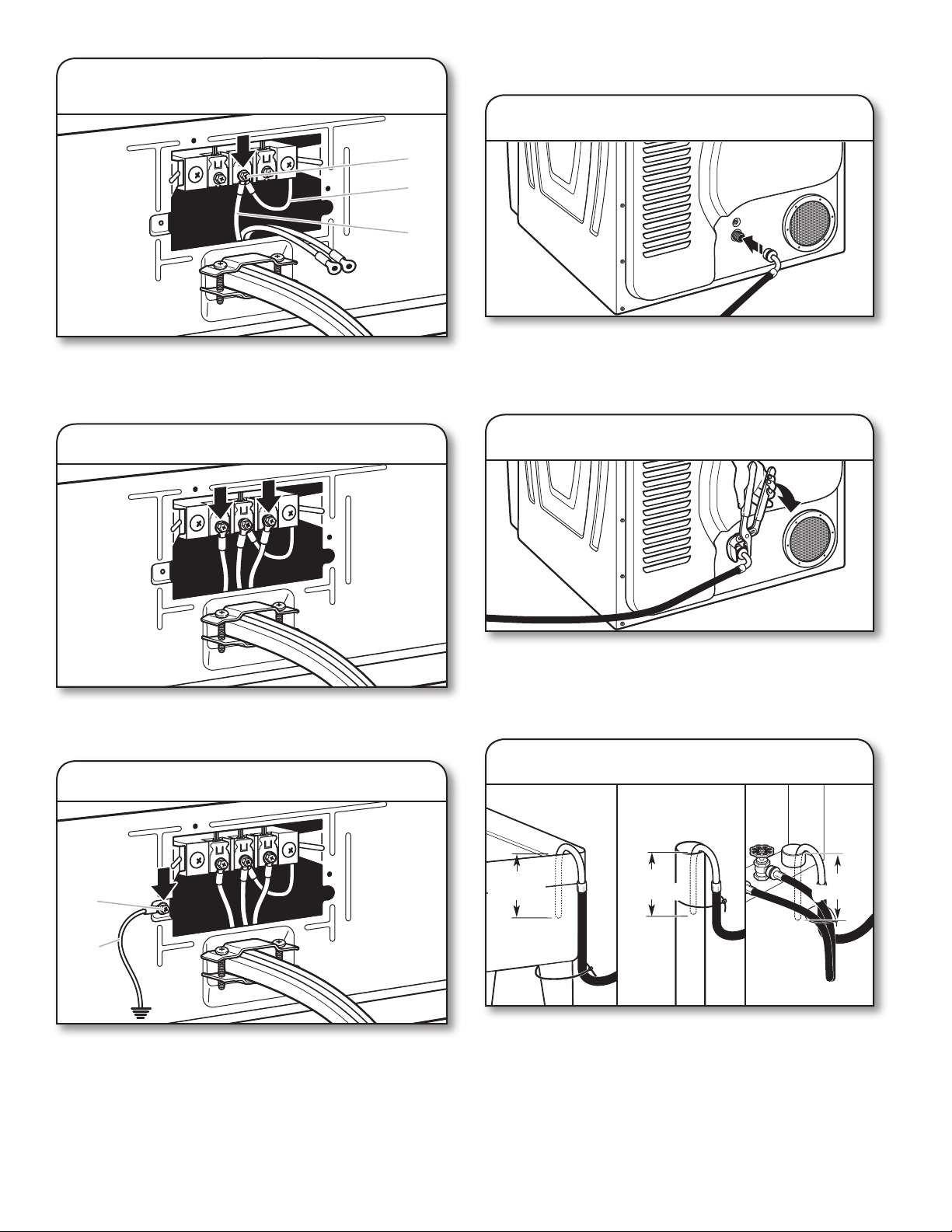
2. Connect neutral ground wire and
neutral wire
B
E
C
Connect neutral ground wire (E) and neutral wire (white or
center wire) (C) of power supply cord or cable under center,
terminal block screw (B). Tighten screw.
CONNECT OUTLET HOSE
1. Attach hose
Attach the goose-neck tting of the provided 6 ft. (1.82 m)
drain hose to the drain valve at the bottom of dryer back
panel. Screw on coupling by hand until it is seated on valve
connector.
3. Connect remaining wires
Place ends of remaining wires under outer terminal block
screws. Tighten screws.
4. Connect external ground wire
A
2. Tighten coupling
Using channel locks, tighten the coupling an additional
two-thirds turn.
NOTE: Do not over-tighten. Damage to the coupling can
result.
3. Secure drain hose system
Laundry Tub Standpipe Wall
4.5"
4.5"
4.5"
(114 mm)
(114 mm)
4.5"
(114 mm)
(114 mm)
(114 mm)
(114 mm)
4.5"
4.5"
G
Connect a separate copper ground wire (G) under the green
external ground conductor screw (A) to an adequate ground.
Finally, reinsert tab of terminal block cover into slot of dryer
rear panel. Secure cover with hold-down screw. Now, go to
“Connect Outlet Hose.”
14
Secure drain hose to laundry tub leg, drain standpipe, or inlet
hoses for wall standpipe with cable tie.
Page 15
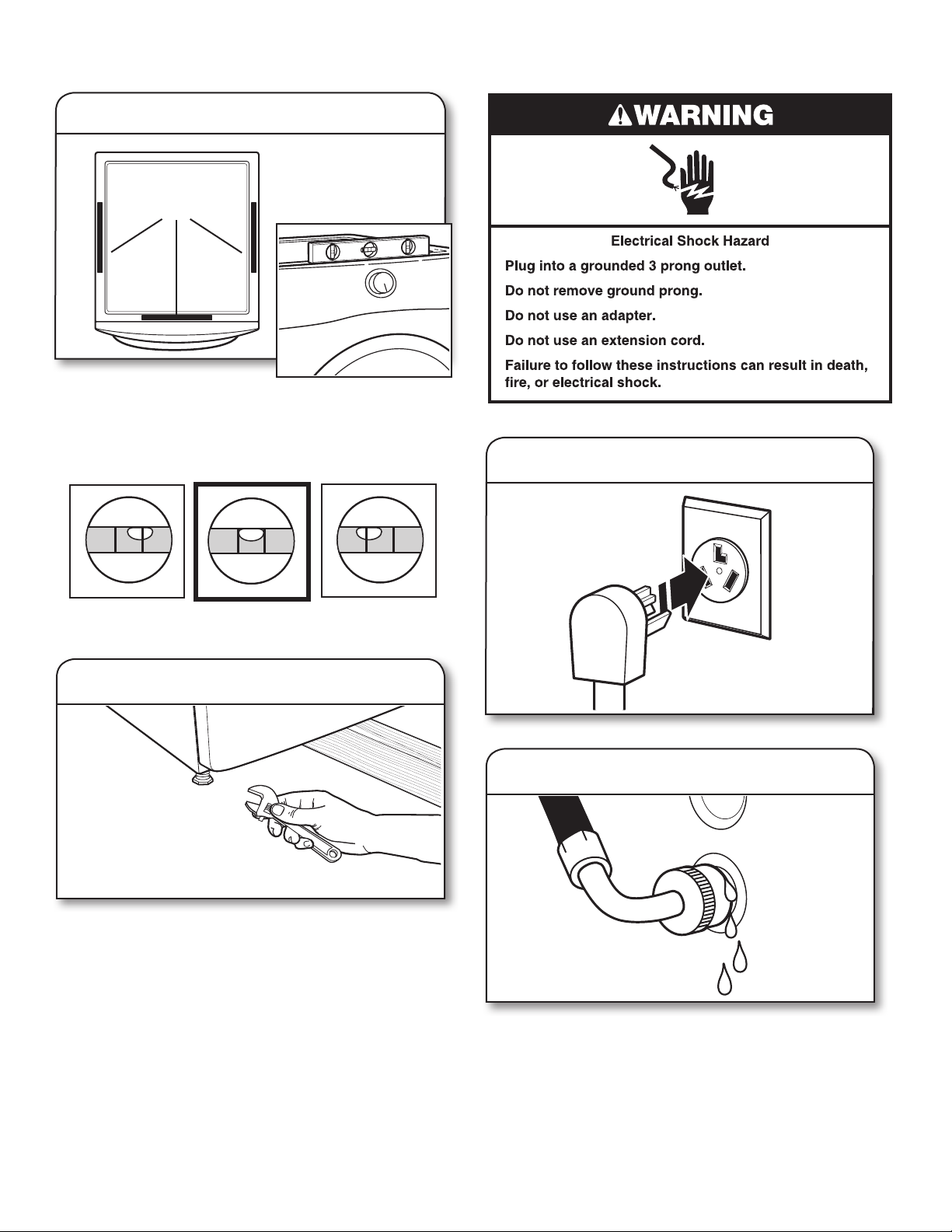
LEVEL DRYER
1. Level dryer
Place
level here
Check levelness of dryer from
side to side. Repeat from front to back.
NOTE: The dryer must be level for the moisture-sensing
system to operate correctly. If forward slope of dryer is
greater than 1" (25 mm), water could run out from front
of lter.
3. Plug into a grounded 3 prong outlet
Not Level LEVEL Not Level
2. Adjust leveling legs
If dryer is not level, prop up using a wood block, use a wrench
to adjust legs up or down, and check again for levelness.
Once dryer is level, make sure all four legs are snug against
the oor and dryer does not rock.
4. Check for leaks
While running the rst cycle, check that there are no leaks
from the drain hose.
15
Page 16
COMPLETE INSTALLATION
CHECKLIST
DOOR REVERSAL (OPTIONAL)
The following instructions are for models with round doors.
Ɨ Check that all parts are now installed. If there is an extra
part, go back through steps to see what was skipped.
Ɨ Check that dryer is level. See “Level Dryer.”
Ɨ Check that you have all of your tools.
Ɨ Dispose of/recycle all packaging materials.
Ɨ Check dryer’s nal location.
Ɨ Remove lm on console and any tape remaining on dryer.
Ɨ Wipe dryer drum interior thoroughly with a damp cloth to
remove any dust.
Ɨ Read “Dryer Use” in your Use and Care Guide.
Ɨ For power supply cord installation, plug into a grounded
outlet. For direct wire installation, turn on power.
Ɨ Select a Timed Dry heated cycle and start dryer.
If dryer will not start, check the following:
• Controls are set to a running or On position.
• Start button has been pressed rmly.
• Dryer is plugged into an outlet and/or electrical
supply.
• Household fuse is intact and tight or circuit breaker
has not tripped.
• Dryer door is closed.
This dryer automatically runs an installation diagnostic routine
at the start of its rst cycle.
NOTE: You may notice an odor when dryer is rst heated.
This odor is common when heating element is rst used.
The odor will go away.
Tools needed:
Min. 8" (203 mm) long
TORX®, T20
screwdrivers
®
and T25
®
†
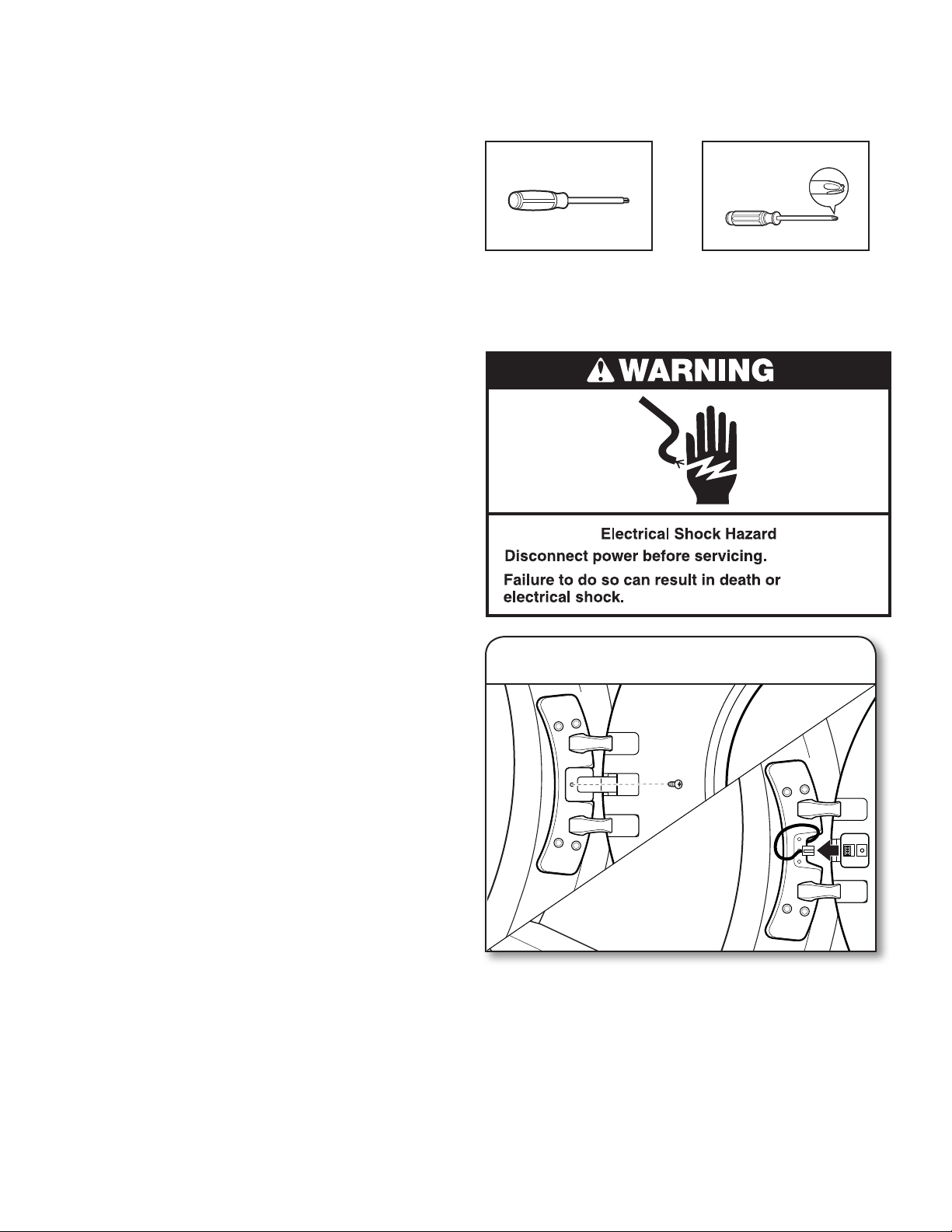
DOORS WITH LCD SCREEN:
#2 Phillips screwdriver
1. Disconnect wiring from door
Using a Phillips screwdriver, remove middle screw in hinge.
Disconnect wiring. Tuck wiring into opening.
16
†®TORX, T20, and T25 are registered trademarks of Acument Intellectual Properties, LLC.
Page 17
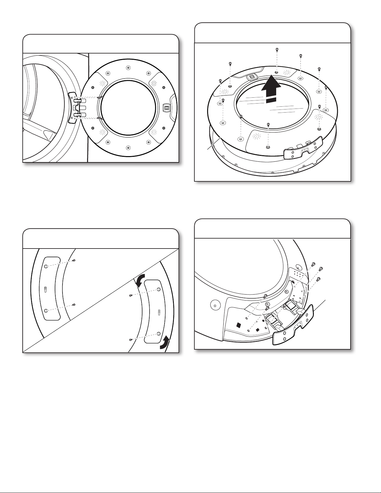
ALL DOORS:
2. Remove door from dryer
IMPORTANT: If the protective lm has not yet been removed
from the dryer, peel the lm from the dryer door before
proceeding.
Using a T25® screwdriver, remove the four screws securing
the door hinge to the dryer and lift the door up and out to
remove. Place the door on a soft towel or other non-scratch
surface.
4.
Remove inner door from outer door
Top of
door
Position the door with the inside of the door facing up.
Using a Phillips screwdriver, remove the 10 screws securing
the inner door to the outer door.
3. Move the door strike
Using a T25® screwdriver, remove the two screws securing
the door strike to the door frame of the dryer. Rotate the strike
180° and attach to the opposite side of dryer door frame with
the two screws removed earlier, as shown.
5. Remove hinge
Hinge
Using a T20® screwdriver, remove the six screws holding the
hinge assembly in place.
17
Page 18
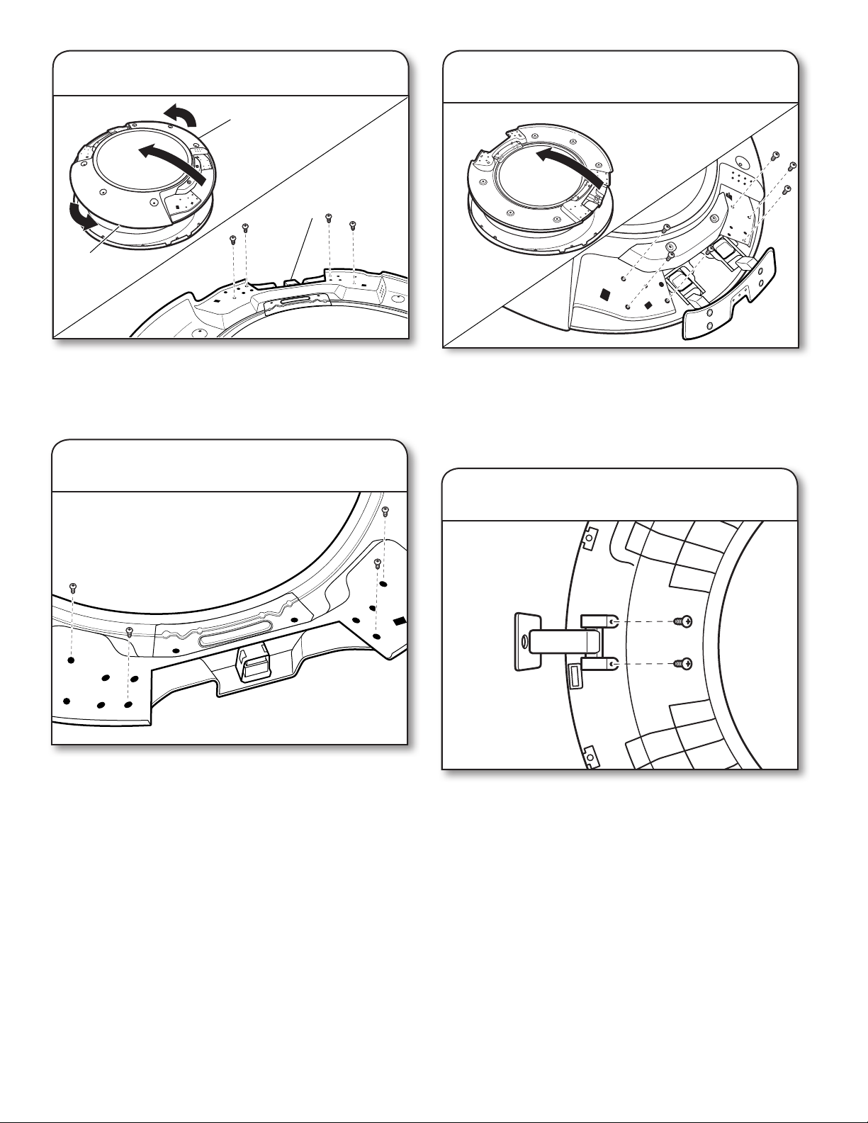
6. Remove latch
Thick section
Thin section
Latch
8.
Reinstall hinge assembly on opposite side
Flip and rotate the inner door 180° so that the thin section is
at the top and the thick section is at the bottom. Using a T25®
screwdriver, remove the four screws securing the latch plate
in place.
7. Reinstall latch on opposite side
Using a T25® screwdriver, reinstall the latch plate on the
opposite side from which it was removed with the four screws
removed earlier.
Flip over the inner door to the left. Using a T20® screwdriver,
reinstall the hinge assembly on the opposite side from which
it was removed.
DOORS WITH LCD SCREEN:
9. Remove rotating assembly
Lift off inner door assembly. Using a Phillips screwdriver,
remove the two screws securing the rotating assembly
to the door.
18
Page 19
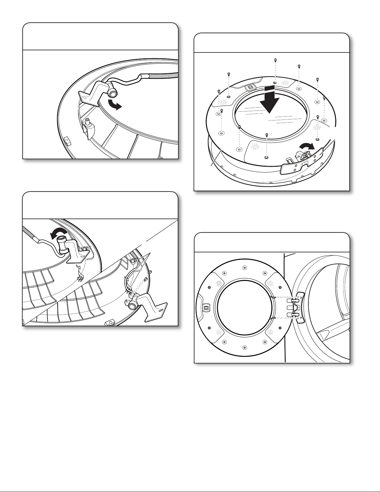
10. Reposition rotating assembly
and tubing
ALL DOORS:
12. Reinstall inner door assembly
Swing
down
Reposition rotating assembly and tubing 180 ° to opposite side
of the door.
11. Rotate assembly bottom and fasten
in place
Press tubing
into indents.
Rotate bottom of assembly 180° towards you and secure
assembly with the two screws removed earlier, using a Phillips
screwdriver. Press tubing into indents.
IMPORTANT: Make sure to swing hinge down in front of
rotating assembly (see Step 12).
Bottom
of door
Position the door with the inside of the door facing up. Using
a Phillips screwdriver, reinstall the 10 screws removed earlier,
securing the inner door to the outer door.
13. Reinstall door on dryer
Doors with electrical wiring: Pull the wire through the front
panel opening before reinstalling the door.
Insert the tabs on the hinge into the mounting slot and slide
down to engage the top tab. Secure in place with the
four T25® screws removed earlier.
19
Page 20
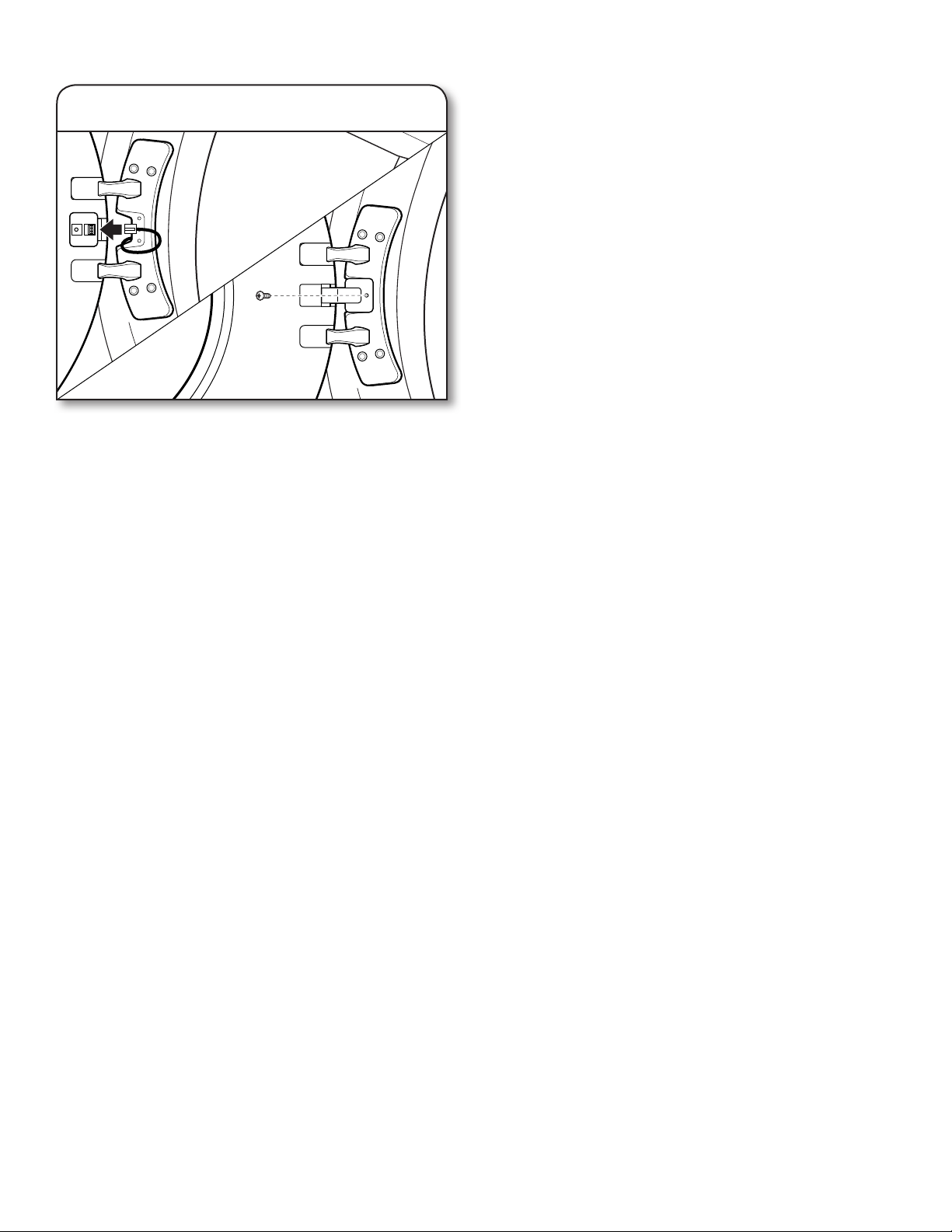
DOORS WITH LCD SCREEN:
6/18
14. Reconnect wiring
Plug in wire. Using a Phillips screwdriver, secure the rotating
assembly to the hinge with the screw removed earlier.
TROUBLESHOOTING
See the Use and Care Guide or visit our website and reference
Frequently Asked Questions to possibly avoid the cost of a
service call.
20
 Loading...