

Whirlpool WGGE4330A070M, WGGE4324A045M, WGGE4336A070M, WGGE4336A090M, WGGE4342A070M Installation Instructions Manual
...
PACKAGE GAS ELECTRIC FURNACES
INSTALLATION INSTRUCTIONS
ATTENTION INSTALLATION PERSONNEL
Prior to installation, thoroughly familiarize yourself with this instruction manual.
Observe all safety warnings.
During installation or repair, caution is to be observed.
It is your responsibility to install the product safely and to educate the customer on its safe use.
Placeholder
for Bar
Code
Keep this literature in a safe place for future reference.
Whirlpool Gold® Model
WGGE43
WPIO-357A
These installation instructions cover the outdoor
installation of single package gas electric heating and
cooling units. See the Specification Sheets or Technical
Manual applicable to your model for information regarding
accessories. Please contact your distributor or our
website for the applicable Specification Sheets referred to
in this manual.
Tradewinds Distributing Company, LLC
14610 Breakers Drive
Jacksonville, Florida 32258

TABLE OF CONTENTS
SAFETY INSTRUCTIONS............................................................... 3
TO THE INSTALLER.......................................................................4
IMPORTANT NOTE TO THE OWNER REGARDING
PRODUCT WARRANTY.................................................................4
REPLACEMENT PARTS ................................................................4
UNIT LOCATION.............................................................................4
Ground Level Installations Only...................................................5
Rooftop Installations Only............................................................5
Roof Curb Installations Only ........................................................5
GENERAL INFORMATION.............................................................6
TRANSPORTATION DAMAGE ......................................................6
RIGGING DETAILS ......................................................................... 6
GAS PIPING ....................................................................................6
High Altitude Derate—U.S. Installations Only .............................7
Check Gas Piping ........................................................................8
ELECTRICAL WIRING..................................................................10
Thermostat Location ..................................................................10
Unit Voltage................................................................................11
Heat Anticipator Setting.............................................................11
CIRCULATING AIR AND FILTERS..............................................11
Airflow Conversion .....................................................................11
Ductwork ....................................................................................11
Filters..........................................................................................12
VENTING .......................................................................................12
CONDENSATE DRAIN .................................................................12
Condensate Drain Connection...................................................12
NORMAL SEQUENCES OF OPERATION...................................12
Heating .......................................................................................12
Cooling .......................................................................................13
Fan Only .....................................................................................13
START-UP, ADJUSTMENTS, AND CHECKS.............................13
Heating Start-Up ........................................................................13
Pre-Operation Checks ...............................................................13
Gas Supply Pressure Measurement..........................................14
Gas Manifold Pressure Measurement and Adjustment ............15
Gas Input Rate Check—Natural Gas Only ................................15
Main Burner Flame Check .........................................................16
Temperature Rise Check............................................................16
External Static Pressure Check .................................................16
Blower Speed Adjustments........................................................16
Limit Check.................................................................................16
UNIT SHUTDOWN........................................................................17
COOLING START-UP...................................................................17
Compressor Protection Devices................................................17
Cooling Refrigerant Charging.....................................................17
TROUBLESHOOTING ..................................................................17
Ignition Control Error Codes ......................................................17
Abnormal Operation—Heating...................................................17
Abnormal Operation—Cooling...................................................18
MAINTENANCE ............................................................................18
Filter Replacement or Cleaning..................................................18
Cabinet Finish Maintenance.......................................................18
Clean Outside Coil—Qualified Servicer Only.............................18
Condenser, Evaporator and Induced Drafter Motors................18
Flame Sensor—Qualified Servicer Only.....................................19
Flue Passages—Qualified Servicer Only ...................................19
Cleaning Flue Passages—Qualified Servicer Only....................19
Main Burner Flame—Qualified Servicer Only ............................19
Burner Flame ..............................................................................19
Cleaning Burners........................................................................19
ACCESSORIES AND FUNCTIONAL PARTS..............................20
Sheet Metal Accessories............................................................20
Functional Parts..........................................................................20
General Information....................................................................20
APPENDIX.....................................................................................20
Blower Performance Data—Single Phase.................................20
Ignition Control Diagnostic Indicator Chart ...............................25
Heating Timing Chart .................................................................26
Cooling Timing Chart .................................................................26
Unit Dimensions .........................................................................27
Minimum Clearances..................................................................27
Wiring Diagram—WGGE4324, 30, 36, 42..................................28
Wiring Diagram—WGGE4324, 30, 36, 42..................................29
Wiring Diagram—WGGE4348, 60..............................................30
Wiring Diagram—WGGE4348, 60..............................................31
ASSISTANCE OR SERVICE.........................................................32
2
SAFETY INSTRUCTIONS
The following symbols and labels are used throughout this manual to indicate immediate or potential safety hazards. It is the owner’s
and installer’s responsibility to read and comply with all safety information and instructions accompanying these symbols. Failure to
heed safety information increases the risk of personal injury, property damage and/or product damage.
Recognize this symbol as a safety precaution.
WARNING
Hazards or unsafe practices could result in property
damage, product damage, severe personal injury or death.
Goodman 1
CAUTION
Hazards or unsafe practices may result in property
damage, product damage, personal injury or death.
WARNING
Do not connect to or use any device that is not designcertified for use with this unit. Serious property damage,
personal injury, reduced unit performance and/or hazardous
conditions may result from the use of such non-approved
devices.
Goodman 36
WARNING
HIGH VOLTAGE!
Disconnect ALL power before servicing.
Multiple power sources may be present.
Goodman 42
WARNING
To avoid property damage, personal injury or death, do
not use this furnace if any part of the furnace has been
under water. Immediately call a qualified service technician
to inspect the furnace and to replace any part of the
control system and any gas control having been under
water.
Goodman 81
WARNING
This unit must not be used as a “construction heater”
during the finishing phases of construction on a new
structure. This type of use may result in premature failure
of the unit due to extremely low return air temperatures
and exposure to corrosive or very dirty atmospheres.
Goodman 79
WARNING
Installation and repair of this unit should
be performed ONLY by individuals meeting
the requirements of an “Entry Level Technician,”
at a minimum, as specified by the Air-Conditioning,
Heating and Refrigeration Institute (AHRI). Attempting
to install or repair this unit without such background may
result in product damage, personal injury or death.
Failure to do so may cause property damage,
personal injury or death.
WARNING
Should overheating occur or the gas supply fail to shut
off, turn off the manual gas shutoff valve external to the
furnace before turning off the electrical supply.
Goodman 43
WARNING
This product contains or produces a chemical or
chemicals which may cause serious illness or death and
which are known to the State of California to cause
cancer, birth defects or other reproductive harm.
Goodman 45
WARNING
To prevent the risk of property damage, personal injury, or
death, do not store combustible materials or use gasoline
or other flammable liquids or vapors in the vicinity of this
unit.
WARNING
If the information in these instructions is not followed
exactly, a fire or explosion may result causing property
damage, personal injury or loss of life.
— Do not store or use gasoline or other flammable vapors
and liquids in the vicinity of this or any other appliance.
— WHAT TO DO IF YOU SMELL GAS
• Do not try to light any appliance.
• Do not touch any electrical switch; do not use any phone
in your building.
• Immediately call your gas supplier from a neighbor’s
phone. Follow the gas supplier’s instructions.
• If you cannot reach your gas supplier, call the fire
department.
— Installation and service must be performed by a
qualified installer, service agency or the gas supplier.
Goodman 42
3
WARNING
Heating unit should not be utilized without reasonable,
routine inspection, maintenance and supervision. If the
building in which any such device is located will be
vacant, care should be taken that such device is
routinely inspected, maintained and monitored. In the
event that the building may be exposed to freezing
temperatures and will be vacant, all water-bearing pipes
should be drained, the building should be properly
winterized and the water source closed. In the event
that the building may be exposed to freezing
temperatures and will be vacant, any hydronic coil units
should be drained as well, and, in such case, alternative
heat sources should be utilized.
Goodman 47
DANGER
CARBON MONOXIDE POISONING HAZARD
Special Warning for Installation of Furnace or Air Handling
Units in Enclosed Areas such as Garages, Utility Rooms or
Parking Areas.
Carbon monoxide producing devices (such as an
automobile, space heater, gas water heater, etc.) should
not be operated in enclosed areas such as unventilated
garages, utility rooms or parking areas because of the
danger of carbon monoxide (CO) poisoning resulting from
the exhaust emissions. If a furnace or air handler is
installed in an enclosed area such as a garage, utility room
or parking area and a carbon monoxide producing device is
operated therein, there must be adequate, direct outside
ventilation.
This ventilation is necessary to avoid the danger of CO
poisoning which can occur if a carbon monoxide producing
device continues to operate in the enclosed area. Carbon
monoxide emissions can be (re)circulated throughout the
structure if the furnace or air handler is operating in any
mode.
Goodman 38
IMPORTANT NOTE TO THE
OWNER REGARDING
PRODUCT WARRANTY
Your warranty certificate is supplied as a separate document with
the unit installed by your contractor. Read the limited warranty
certificate carefully to determine what is and is not covered. Keep
the warranty certificate in a safe place. If you are unable to locate
the warranty certificate, please contact your installing contractor,
or contact customer service at 1-866-944-7575 to obtain a copy.
To receive the 10-Year Parts Limited Warranty, online registration
must be completed within 60 days of installation. Online
registration is not required in California or Quebec.
Full warranty details and instructions are available at
www.whirlpoolhvac.com.
To register your unit, go to www.whirlpoolhvac.com. Click on the
manufacturer’s Comfort Commitment
the bottom center of the home page. Next, click on the Click
Here to Register Your Product link located at the top center of the
page, and complete the forms in the manner indicated.
TM
Warranty link located at
REPLACEMENT PARTS
When reporting shortages or damages, or ordering repair parts,
give the complete product model and serial numbers as stamped
on the unit’s nameplate. Replacement parts for this product are
available through your contractor or local distributor. For the
location of your nearest distributor, consult the white business
pages, the yellow page section of the local telephone book or
contact:
Tradewinds Distributing Company, LLC
14610 Breakers Drive
Jacksonville, Florida 32258
1-866-944-7575
If you are replacing an air handler, the system must be
manufacturer-approved and Air-Conditioning, Heating, and
Refrigeration Institute (AHRI) matched.
NOTE: Installation of unmatched systems is strongly
discouraged.
UNIT LOCATION
WARNING
CO can cause serious illness including permanent brain
damage or death.
TO THE INSTALLER
Before installing this unit, please read this manual to familiarize
yourself on the specific items which must be adhered to,
including maximum external static pressure to unit, air
temperature rise, minimum or maximum CFM and motor speed
connections.
4
To prevent possible equipment damage, property damage,
personal injury or death, the following bullet points must
be observed when installing the unit.
■ For proper flame pattern within the heat exchanger and
proper condensate drainage, the unit must be mounted level.
■ The flue outlet hood must be at least 12" (30.5 cm) from any
opening through which flue gases could enter a building, and
at least 36" (91.4 cm) above any forced air inlet located within
10 ft (3 m). The economizer/manual fresh air intake/motorized
fresh air intake and combustion air inlet mounted on the unit
are not affected by this restriction.
Goodman 50
■ To avoid possible corrosion of the heat exchanger, do not
locate the unit in an area where the outdoor air (for example,
combustion air for the unit) will be frequently contaminated by
compounds containing chlorine or fluorine. Common sources
of such compounds include swimming pool chemicals and
chlorine bleaches, paint stripper, adhesives, paints,
varnishes, sealers, waxes (which are not yet dried) and
solvents used during construction and remodeling. Various
commercial and industrial processes may also be sources of
chlorine/fluorine compounds.
■ To avoid possible illness or death of the building occupants,
do not locate outside air intake device (economizer, manual
fresh air intake, motorized fresh air intake) too close to an
exhaust outlet, gas vent termination or plumbing vent outlet.
For specific distances required, consult local codes.
■ Allow minimum clearances from the enclosure for fire
protection, proper operation, and service access. These
clearances must be permanently maintained.
■ The combustion air inlet and flue outlet hoods on the unit
must never be obstructed. If used, do not allow the
economizer/manual fresh air damper/ motorized fresh air
damper to become blocked by snow or debris. In some
climates or locations, it may be necessary to elevate the unit
to avoid these problems.
■ When the unit is heating, the temperature of the return air
entering the unit must be between 50°F and 100°F (10ºC and
38ºC).
Ground Level Installations Only
■ When the unit is installed on the ground adjacent to the
building, a level concrete (or equal) base is recommended.
Prepare a base that is 3" (7.6 cm) larger than the package unit
footprint and a minimum of 3" (7.6 cm) thick.
■ The base should also be located where no runoff of water
from higher ground can collect in the unit.
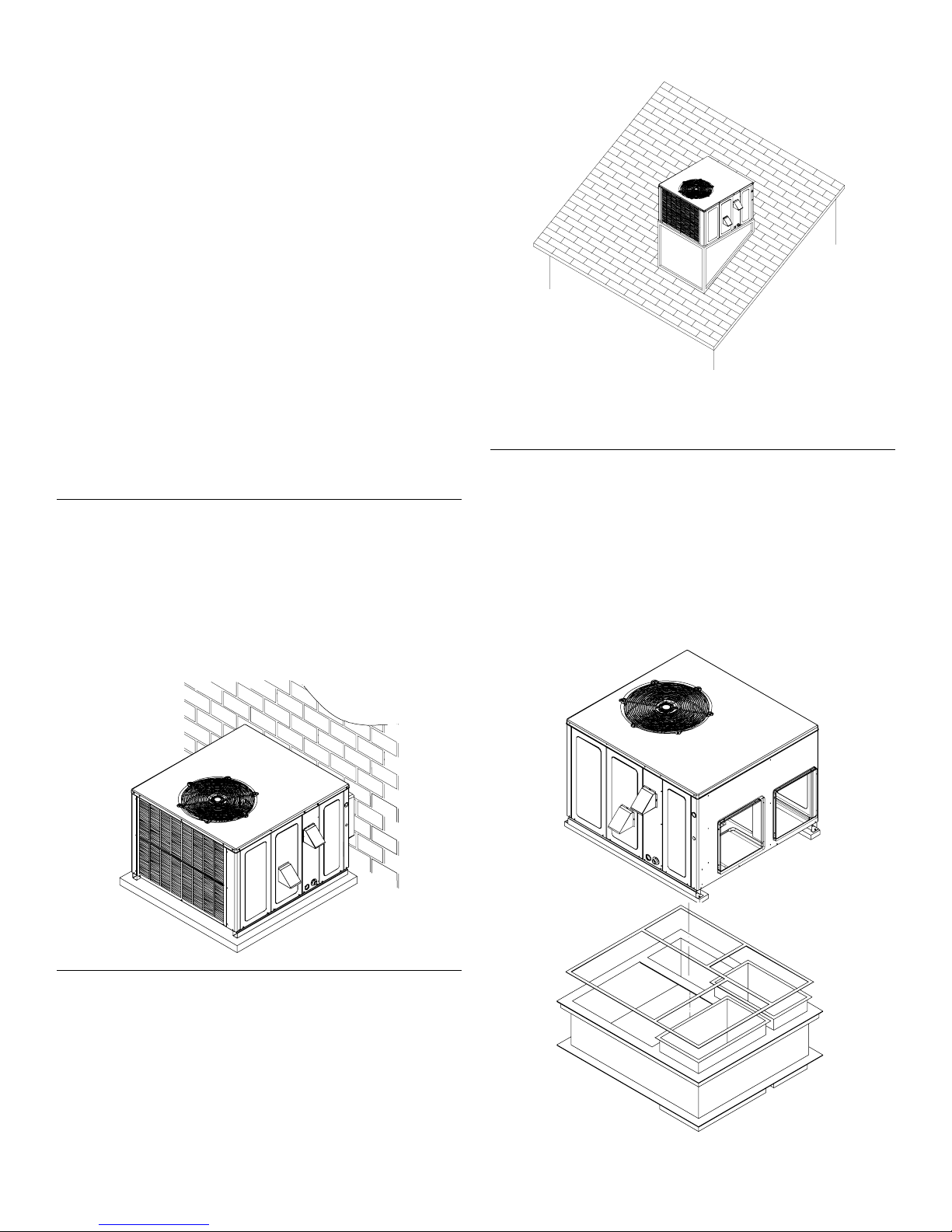
Rooftop Installation
■ The unit may be installed directly on wood floors or on Class
A, Class B, or Class C roof covering material.
■ To avoid possible personal injury, a safe, flat surface for
service personnel should be provided.
Roof Curb Installations Only
■ Sufficient structural support must be determined prior to
locating and mounting the curb and package unit.
■ Ductwork must be constructed using industry guidelines. The
ductwork must be placed into the roof curb before mounting
the package unit.
■ Curb insulation, cant strips, flashing and general roofing
material are furnished by the contractor.
Roof Curb Installation
Ground Level Installation
Rooftop Installations Only
NOTE: To ensure proper condensate drainage, unit must be
installed in a level position.
■ To avoid possible property damage or personal injury, the
roof must have sufficient structural strength to carry the
weight of the unit(s) and snow or water loads as required by
local codes. Consult a structural engineer to determine the
weight capabilities of the roof.
5
GENERAL INFORMATION
RIGGING DETAILS
WARNING
To prevent property damage, personal injury or death,
due to fire, explosions, smoke, soot, condensation,
electric shock or carbon monoxide, this unit must be
properly installed, repaired, operated and maintained.
This unit is approved for outdoor installation only. To assure that
your unit operates safely and efficiently, it must be installed,
operated, and maintained in accordance with these installation
and operating instructions, all local building codes and
ordinances, or in their absence, with the latest edition of the
National Fuel Gas Code NFPA54/ANSI Z223.1 and National
Standard of Canada CAN/CSA B149 Installation Codes.
The heating and cooling capacities of the unit should be greater
than or equal to the design heating and cooling loads of the area
to be conditioned. The loads should be calculated by an
approved method or in accordance with A.S.H.R.A.E. Guide or
Manual J - Load Calculations published by the Air Conditioning
Contractors of America.
Obtain from:
American National Standards Institute
430 Broadway
New York, NY 10018
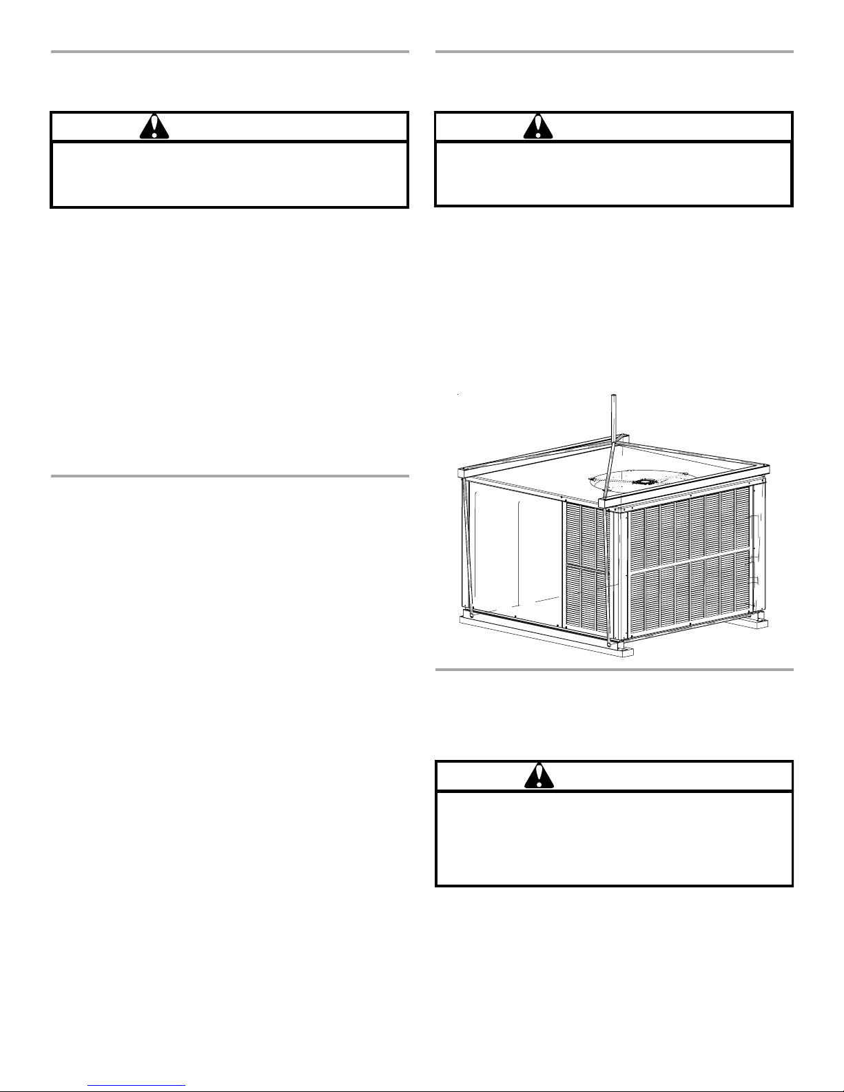
TRANSPORTATION DAMAGE
WARNING
To prevent property damage, the unit should remain in an
upright position during all rigging and moving operations.
To facilitate lifting and moving when a crane is used,
place the unit in an adequate cable sling.
IMPORTANT: If using the bottom discharge with the roof curb,
the ductwork should be attached to the curb prior to installing the
unit. Ductwork dimensions are shown in the roof curb installation
instructions.
Refer to “Roof Curb Installations Only” for the proper curb
installation. Curbing must be installed in compliance with the
National Roofing Contractors Association Manual.
Lower the unit carefully onto the roof mounting curb. While
rigging the unit, the center of gravity will cause the condenser
end to be lower than the supply air end.
Rigging
Check the carton upon arrival for external damage. If damage is
found, a request for inspection by carrier agent should be made
in writing immediately.
Carefully inspect the unit for damage including damage to the
cabinetry. Any bolts or screws which may have loosened in
transit must be retightened. In the event of damage, the receiver
should:
1. Make notation on delivery receipt of any visible damage to
shipment or container.
2. Notify carrier promptly and request an inspection.
3. In case of concealed damage, carrier should be notified as
soon as possible—preferably within 5 days.
4. File the claim with the following supporting documents:
a) Original Bill of Lading, certified copy, or indemnity bond.
b) Original paid freight bill or indemnity in lieu thereof.
c) Original invoice or certified copy thereof, showing trade
and other discounts or reductions.
d) Copy of the inspection report issued by carrier
representative at the time damage is reported to the
carrier. The carrier is responsible for making prompt
inspection of damage and for a thorough investigation of
each claim. The distributor or manufacturer will not
accept claims from dealers for transportation damage.
NOTE: When inspecting the unit for transportation damage,
remove all packaging materials. Recycle or dispose of the
packaging material according to local codes.
GAS PIPING
IMPORTANT NOTE: This unit is factory set to operate on natural
gas at the altitudes shown on the rating plate.
WARNING
To avoid property damage, personal injury or death when
either using propane gas alone or at higher altitudes,
obtain and install the proper conversion kit(s). Failure to
do so can result in unsatisfactory operation and/or
equipment damage. High altitude kits are for U.S.
installations only and are not
The rating plate is stamped with the model number, type of gas
and gas input rating. Make sure the unit is equipped to operate
on the type of gas available. Conversion to LP gas is permitted
with the use of the factory-authorized conversion kit LPM-03.
Goodman 89
approved for use in Canada.
6
NOTES:
A
■ LPT-00A may be used on models with AA revisions.
■ LPT-03 is compatible with both the White Rodgers and the
Honeywell gas control valves.
NOTE: Inlet gas pressure must not exceed the maximum value
shown in the Inlet Gas Pressure chart.
Inlet Gas Pressure
Natural Minimum: 5.0" W.C. Maximum: 10.0" W.C.
Propane Minimum: 11.0" W.C. Maximum: 13.0" W.C.
The minimum supply pressure should not vary from that shown in
the Inlet Gas Pressure chart, because this could prevent the unit
from having dependable ignition. In addition, gas input to the
burners must not exceed the rated input shown on the rating
plate. Overfiring of the unit could result in premature heat
exchanger failure.
High Altitude Derate—U.S. Installations Only
IMPORTANT: The gas/electric units naturally derate with
altitude. Do not attempt to increase the firing rate by changing
orifices or increasing the manifold pressure. This can cause poor
combustion and equipment failure. At all altitudes, the manifold
pressure must be within 0.3" W.C. of that listed on the nameplate
for the fuel used. At all altitudes and with either fuel, the air
temperature rise must be within the range listed on the unit
nameplate.
Refer to the installation manual provided with the LP kit for
conversion from Natural gas to propane gas and for altitude
adjustments.
NOTE: Up to 7,000 ft (2,134 m), no changes are required; above
7,000 ft (2,134 m), refer to High Altitude Kit HA-02.
IMPORTANT NOTE: To avoid possible unsatisfactory operation
or equipment damage due to under firing of equipment, do not
undersize the Natural/propane gas piping from the meter/tank to
the unit. When sizing a trunk line, include all appliances on that
line that could be operated simultaneously.
The rating plate is stamped with the model number, type of gas
and gas input rating. Make sure that the unit is equipped to
operate on the type of gas available. The gas line installation
must comply with local codes, or in the absence of local codes,
with the latest edition of the National Fuel Gas Code NFPA 54/
ANSI Z223.1.
Pressure = 0.50 psig or less and pressure drop of 0.3" W.C.
(Based on 0.60 specific gravity gas)
Btu/h Unit Input
CFH =
Heating Value of Gas (Btu/Cu Ft)
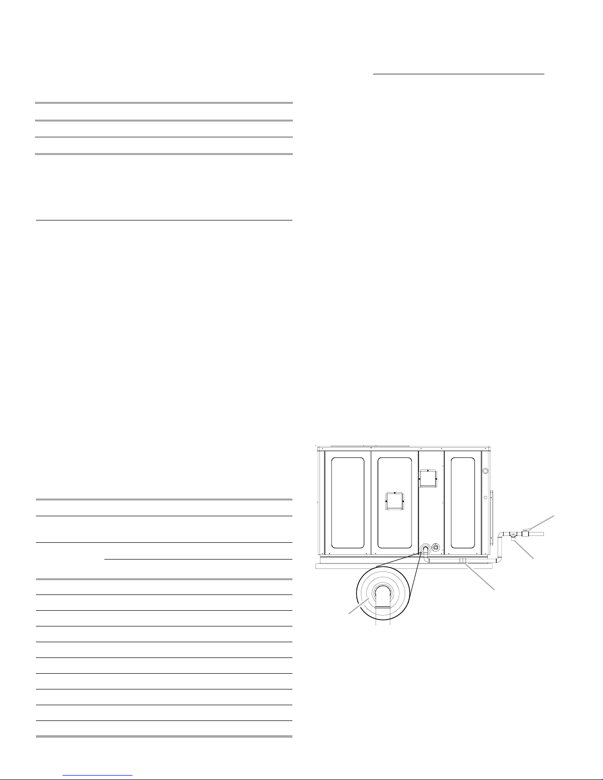
Refer to the “Proper Piping Practice” illustration for the general
layout at the unit. The following rules apply:
1. Use black iron pipe and fittings for the supply piping. The use
of a flex connector and/or copper piping is permitted as long
as it is in agreement with local codes.
2. Use pipe joint compound on male threads only. Pipe joint
compound must be resistant to the action of the fuel used.
3. Use ground joint unions.
4. Install a drip leg to trap dirt and moisture before it can enter
the gas control valve. The drip leg must be a minimum of 3"
(7.6 cm) long.
5. Use 2 pipe wrenches when making the connection to the gas
control valve to keep the valve from turning.
6. Install a manual shutoff valve in a convenient location (within
6 ft [1.8 m] of the unit) between the meter and the unit.
7. Tighten all joints securely.
8. The unit must be connected to the building piping by one of
the following methods:
■ Rigid metallic pipe and fittings
■ Semirigid metallic tubing and metallic fittings (aluminum
alloy tubing must not be used in exterior locations)
■ Listed gas appliance connectors used in accordance with
the terms of their listing that are completely in the same
room as the equipment
■ The connector or tubing must be protected against
physical and thermal damage. Aluminum alloy tubing and
connectors must be coated to avoid external corrosion
when in contact with masonry, plaster or insulation or are
subject to repeated wettings by liquids (water—not
rainwater, detergents or sewage).
Proper Piping Practice
Natural Gas Connection
Natural Gas Capacity of Pipe in Cu Ft (m
(CFH)
Nominal Black Pipe Size
Length of
Pipe—ft (m)
10 (3) 132 278 520 1,050 1,600
20 (6.1) 92 190 350 730 1,100
30 (9.2) 73 152 285 590 980
40 (12.2) 63 130 245 500 760
50 (15.2) 56 115 215 440 670
60 (18.3) 50 105 195 400 610
70 (21.3) 46 96 180 370 560
80 (24.4) 43 90 170 350 530
90 (27.4) 40 84 160 320 490
100 (30.5) 38 79 150 305 460
¹⁄₂" ³⁄₄"1" 1¹⁄₄"1¹⁄₂"
3
) of Gas Per Hour
B
C
D
A. Manual shutoff valve
B. Drip leg
C. Ground joint union (installed upstream of
gas control valve)
D. Grommet
NOTE: The unit gas supply entrance is factory sealed with plugs.
Keep plugs in place until gas supply is ready to be installed. Once
ready, replace the plugs with the supplied grommets and install
gas supply line.
7
Check Gas Piping
D
CAUTION
To prevent property damage or
the following instructions must be performed regarding
gas connections and pressure testing:
-The unit and its gas connections must be leak tested
before placing in operation. Because of the danger of
explosion or fire, never use a match or open flame to test
for leaks. Never exceed specified pressures for testing.
Higher pressure may damage
overfiring which may result in premature heat exchange
failure.
-The unit and its gas shutoff valve must be disconnected
from the gas supply during any pressure testing of that
system at test pressures in excess of ¹⁄₂ psig (3.48 kPa).
-This unit must be isolated from the gas supply system
by closing its manual shutoff valve during any pressure
testing of the gas supply piping system at test pressures
equal to or less than ¹⁄₂ psig (3.48 kPa).
Goodman 90
personal injury due to fire,
gas control valve and cause
NOTE: Propane gas conversion kits must be installed to convert
units to propane gas.
A gas detecting warning system is the only reliable way to detect
a propane gas leak. Rust can reduce the level of odorant in
propane gas. Do not rely on your sense of smell. Contact a local
propane gas supplier about installing a gas detecting warning
system.
All propane gas equipment must conform to the safety standards
of the National Board of Fire Underwriters, NBFU Manual 58.
For satisfactory operation, propane gas supply pressure must be
within 9.7" W.C. to 10.3" W.C. at the furnace manifold with all gas
appliances in operation.
Maintaining proper gas pressure depends on 3 main factors:
■ Vaporization rate, depending on the temperature of the liquid
and the wetted surface area of the container or containers.
■ Proper pressure regulation. Two-stage regulation is
recommended for both cost and efficiency.
■ Pressure drop in the lines between the regulators, and
between 2
required will depend on the length of the pipe run and the
total load of all appliances.
nd
stage regulator and the appliance. Pipe size
WARNING
To avoid property damage or personal injury, be sure
there is NO OPEN FLAME in the vicinity during air
bleeding.
There will be air in the gas supply line after testing for leaks on a
new installation. Therefore, the air must be bled from the line by
loosening the ground joint union until pure gas is expelled.
Tighten the ground joint union and wait for 5 minutes until all gas
has been dissipated in the air. Be certain there is no open flame in
the vicinity during air bleeding procedure. The unit is placed in
operation by closing the main electrical disconnect switch for the
unit.
Goodman 91
WARNING
To avoid property damage, personal injury or death due
to fire or explosion caused by a propane gas leak, install
a gas detecting warning device. Since rust can reduce the
level of odorant in propane gas, a gas detecting warning
device is the only reliable way to detect a propane gas
leak. Contact a local propane gas supplier about installing
a gas detecting warning device.
Goodman 92
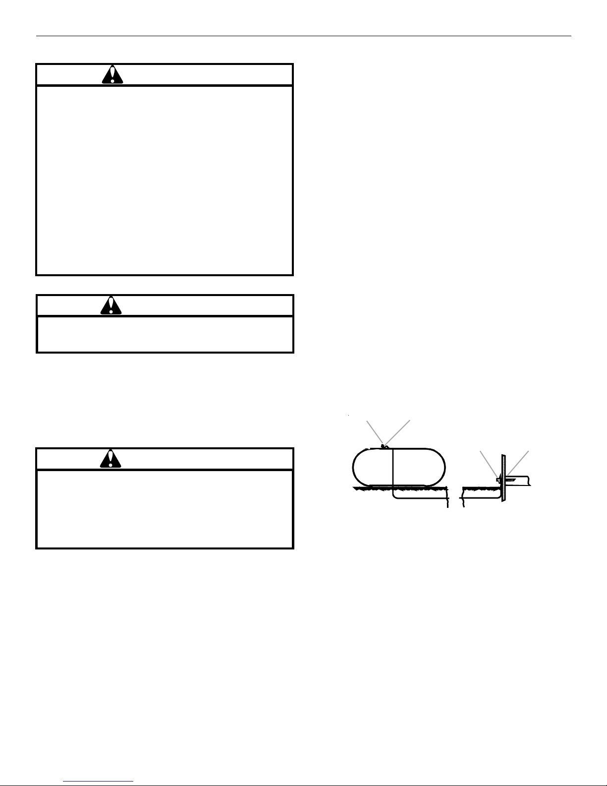
Tanks and Piping
Complete information regarding tank sizing for vaporization,
recommended regulator settings, and pipe sizing is available
from most regulator manufacturers and propane gas suppliers.
Since propane gas will quickly dissolve white lead and most
standard commercial compounds, special pipe dope must be
used. Shellac-based compounds resistant to the actions of
liquefied petroleum gases are satisfactory.
Propane Gas Installation—Typical
A
A. 1st stage regulator
B. 5 to 15 psig (20 psig maximum)
NOTE: 200 psig maximum tank pressure.
B
C
C. 2nd stage regulator
D. Continuous 11" W.C.
8

st
Sizing Between 1
Maximum propane capacities listed are based on 1 psig pressure drop at 10 psig setting. Capacities in 1,000 Btu/h.
and 2nd Stage Regulator*
Propane Gas Pipe Sizing Chart I
Tubing Size, O.D., Type L Nominal Pipe Size, Schedule 40
Pipe or Tubing
Length—ft (m)
30 (9.2) 309 700 1,303 2,205 3,394 1,843 3,854
40 (12.2) 265 599 1,115 1,887 2,904 1,577 3,298
50 (15.2) 235 531 988 1,672 2,574 1,398 2,923
60 (18.3) 213 481 896 1,515 2,332 1,267 2,649
70 (21.3) 196 446 824 1,394 2,146 1,165 2,437
80 (24.4) 182 412 767 1,297 1,996 1,084 2,267
90 (27.4) 171 386 719 1,217 1,873 1,017 2,127
100 (30.5) 161 365 679 1,149 1,769 961 2,009
150 (45.7) 130 293 546 923 1,421 772 1,613
200 (61) 111 251 467 790 1,216 660 1,381
250 (76.2) 90 222 414 700 1,078 585 1,224
300 (91.4) 89 201 378 634 976 530 1,109
³⁄₈" ¹⁄₂" ⁵⁄₈" ³⁄₄" ⁷⁄₈" ¹⁄₂" ³⁄₄"
350 (106.7) 82 185 345 584 898 488 1,020
400 (121.9) 76 172 321 543 836 454 949
To convert to capacities at 15 psig settings—multiply by 1.13. To convert to capacities at 5 psig settings—multiply by 0.879.
Sizing Between Single or 2nd Stage Regulator and Appliance*
Maximum propane capacities listed are based on ¹⁄₂" W.C. pressure drop at 11" W.C. setting. Capacities in 1,000 Btu/h.
Propane Gas Pipe Sizing Chart II
Tubing Size, O.D. Type L Nominal Pipe Size Schedule 40
Pipe or Tubing Length—ft (m) ³⁄₈" ¹⁄₂" ⁵⁄₈" ³⁄₄" ⁷⁄₈" ¹⁄₂" ³⁄₄"1" 1¹⁄₄"1¹⁄₂"
10 (3) 49 110 206 348 539 291 608 1,146 2,353 3,525
20 (6.1) 34 76 141 239 368 200 418 788 1,617 2,423
30 (9.2) 27 61 114 192 296 161 336 632 1,299 1,946
40 (12.2) 23 52 97 164 253 137 284 541 1,111 1,665
50 (15.2) 20 46 86 146 224 122 255 480 985 1,476
60 (18.3) 19 42 78 132 203 110 231 436 892 1,337
80 (24.4) 16 36 67 113 174 94 198 372 764 1,144
100 (30.5) 14 32 59 100 154 84 175 330 677 1,014
125 (38.1) 12 28 52 89 137 74 155 292 600 899
150 (45.7) 11 26 48 80 124 67 141 265 544 815
200 (61) 10 22 41 69 106 58 120 227 465 697
250 (76.2) 9 19 36 61 94 51 107 201 412 618
300 (91.4) 8 18 33 55 85 46 97 182 374 560
350 (106.7) 7 16 30 51 78 43 89 167 344 515
400 (121.9) 7 15 28 47 73 40 83 156 320 479
Data in accordance with NFPA pamphlet Number 54.
9
WARNING
To prevent property damage or serious personal injury
due to fire or explosion caused by a propane gas leak,
install a gas detecting warning device.
If the propane gas unit is installed in an excavated area
or a confined space, a warning device is required due to:
-Propane gas is heavier than air and any leaking gas
can settle in any low areas or confined spaces.
-Propane gas odorant may fade, making the gas
undetectable except with a warning device.
Goodman 102
Refer to the unit wiring diagram for electrical connections. When
installed, the unit must be electrically grounded in accordance
with local codes or in the absence of local codes, with the
National Electrical Code, ANSI/NFPA No. 70, and/or the CSA
C22.1 Electrical Code. Ensure that the low voltage connections
are waterproof.
WARNING
To avoid the risk of electrical shock, wiring to the unit
must be polarized and grounded.
Goodman 70
ELECTRICAL WIRING
Thermostat Location
Mount the thermostat approximately 5 ft (1.5 m) above the floor,
in an area that has an inside, vibration-free wall and has good air
circulation.
Movement of air must not be obstructed by furniture, door,
draperies, etc. The thermostat must not be mounted where it will
be affected by drafts, hot or cold water pipes or air ducts in walls,
radiant heat from fireplace, lamps, the sun, television, etc.
Consult the Instruction Sheet packaged with the thermostat for
mounting instructions.
All units have 1 stage of heating and 1 stage of mechanical
cooling. Units which will have economizers may use thermostats
with 1 or 2 stages of cooling.
WARNING
HIGH VOLTAGE!
Disconnect ALL power before servicing.
Multiple power sources may be present.
Failure to do so may cause property damage,
personal injury or death.
Goodman 42
WARNING
To avoid the risk of fire or equipment damage, use
copper conductors.
Goodman 22
CAUTION
Label all wires prior to disconnection when servicing
controls.
Wiring errors can cause improper
operation. Verify proper operation after servicing.
For unit protection, use a time-delay fuse or HACR circuit breaker
that is in excess of the circuit ampacity, but less than or equal to
the maximum overcurrent protection device.
IMPORTANT: Do not exceed the maximum overcurrent device
size shown on the unit data plate.
All line voltage connections must be made through weatherproof
fittings. All exterior power supply and ground wiring must be in
approved weatherproof conduit. Low voltage wiring from the unit
control panel to the thermostat requires coded cable.
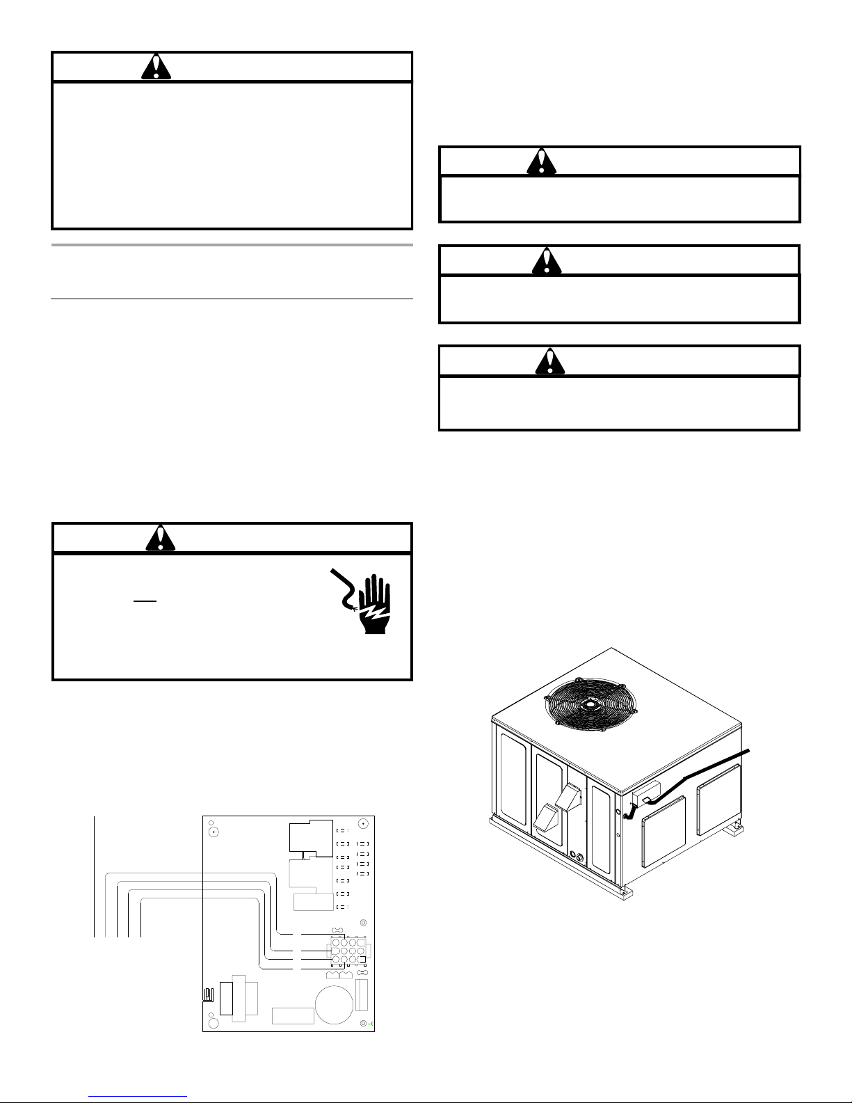
Electrical Power Directly to Junction Box
NOTE: Junction box location shown is optional and is for
illustration purposes only.
Goodman 59
and
dangerous
The units are designed for operation on 60 hertz current and at
voltages as shown on the rating plate. All internal wiring in the
unit is complete. It is necessary to bring in the power supply to
the contactor as shown on the unit wiring diagram which is
supplied with each unit. 24-volt wiring must be connected
between the unit control panel and the room thermostat.
Low Voltage Wiring
B18099-18
MODEL
1068-400
C
Low Voltage
Connector
GWYR
24VAC 50/60Hz 400mA MAX.
ANSI Z21.20 AUTOMATIC IGNITION SYSTEM
COMPRESSOR
BREAK FOR TWO STAGE
T2
10
1068-83-400A
COOL
K4
K3
K2
K1
R
11
Y
W
G
FUSE 3 AMP MAX
C22
L2L2L2L2
L1 HEATUNUSED
L1DI
9FS6
12
3
3
659
12
9
6
12
3
2
2
8
11
8
5
11
4
7
1
1
10
10
4
7
10
12
4
7
P1
F1
ECON
120
135
P3
150
P2
SPEED-UP
T1
 Loading...