

Whirlpool WGFM195, WFD195, WFM195, WFD193 Installation Instructions Manual
GAS-FIRED WARM AIR FURNACE INSTALLATION INSTRUCTIONS
(Type FSP Category IV Direct or Nondirect Vent Air Furnace)
ATTENTION INSTALLATION PERSONNEL
As a professional installer, you have an obligation to know the product better than the customer. This includes all
safety precautions and related items. Prior to actual installation, thoroughly familiarize yourself with this instruction
manual. Pay special attention to all safety warnings. Often during installation or repair, it is possible to place
yourself in a position which is more hazardous than when the unit is in operations.
Remember, it is your responsibility to install the product safely and to know it well enough to be able to instruct a
customer in its safe use. Safety is a matter of common sense...a matter of thinking before acting. Most dealers have
a list of specific good safety practices...follow them.
The precautions listed in this installation manual are intended as supplemental to existing practices. However, if
there is a direct conflict between existing practices and the content of this manual, the precautions listed here take
precedence.
ceholder
for Bar
Code
Whirlpool Gold® Models
WGFM195, WFD195,
WFD193, WFM195
WPIO-299N
These furnaces comply with requirements embodied in the
American National Standard/National Standard of Canada ANSI
Z21.47 CSA-2.3 Gas Fired Central Furnaces.
NOTE: Please contact your distributor or our website for
applicable Specification Sheet referred to in this manual.
Tradewinds Distributing Company, LLC
14610 Breakers Drive
Jacksonville, Florida 32258

TABLE OF CONTENTS
GAS FURNACE SAFETY PRECAUTIONS....................................3
Electrostatic Discharge (ESD) Precautions..................................4
PRODUCT DESCRIPTION AND APPLICATION ..........................4
Shipping Inspection .....................................................................4
To The Installer.............................................................................4
Important Note to the Owner Regarding Product Warranty .......4
Component Identification.............................................................5
Product Application......................................................................5
LOCATION REQUIREMENTS AND CONSIDERATIONS ............6
Clearances and Accessibility.......................................................7
Furnace Suspension ....................................................................8
Existing Furnace Removal ...........................................................8
Thermostat Location ....................................................................8
COMBUSTION AND VENTILATION AIR REQUIREMENTS........8
INSTALLATION POSITIONS.......................................................11
HORIZONTAL APPLICATIONS AND CONSIDERATIONS........11
General .......................................................................................11
Drain Trap and Lines..................................................................11
Leveling ......................................................................................11
Alternate Vent/Flue Connections ...............................................11
Alternate Electrical and Gas Line Connections .........................13
Drain Pan....................................................................................13
Freeze Protection .......................................................................13
Furnace Suspension ..................................................................13
PROPANE GAS/HIGH ALTITUDE INSTALLATIONS.................13
VENT/FLUE PIPE AND COMBUSTION AIR PIPE......................13
General .......................................................................................13
Dual Certification: Nondirect/Direct Vent...................................14
Materials and Joining Methods..................................................14
Proper Vent/Flue and Combustion Air Piping Practices ...........14
Termination Locations................................................................14
Canadian Venting Requirements ...............................................15
Standard Furnace Connections.................................................15
Vent/Flue Pipe............................................................................15
Combustion Air Pipe—Direct Vent Installations........................15
Combustion Air Pipe—Nondirect Vent Installations..................16
Alternate Furnace Connections .................................................16
Alternate Vent/Flue Location......................................................16
Nondirect Vent (Single Pipe) Piping...........................................18
Vent/Flue Pipe Lengths and Diameters.....................................18
Vent/Flue Pipe Terminations......................................................18
Direct Vent (Dual Pipe) Piping....................................................19
Vent/Flue and Combustion Air Pipe Lengths and Diameters....19
Vent/Flue and Combustion Air Pipe Terminations ....................20
Vent/Intake Terminations for Installation of Multiple
Direct Vent Furnaces..................................................................21
Concentric Vent Termination .....................................................22
Side Wall Vent Kit.......................................................................22
CONDENSATE DRAIN LINES AND DRAIN TRAP.....................22
Standard Right or Left Side Drain Hose Connections...............22
Upright Installations—Trap on Right Side .................................22
Upright Installations—Trap on Left Side....................................23
Upright Drain Trap Mounting—Left or Right Side Panel...........24
Horizontal Installations—Right Side Down................................24
Horizontal Installations—Left Side Down ..................................24
Horizontal Drain Trap Mounting—Left or Right Side Panel.......25
ELECTRICAL CONNECTIONS....................................................25
Wiring Harness...........................................................................25
115-Volt Line Connections.........................................................25
Junction Box Relocation............................................................26
24-Volt Thermostat Wiring .........................................................26
WFM19 Furnace with 2-Stage Condenser Field Wiring............26
115-Volt Line Connection of Accessories (Humidifier and
Electronic Air Cleaner)................................................................27
GAS SUPPLY AND PIPING..........................................................28
High Altitude Derate ...................................................................28
Propane Gas Conversion...........................................................28
Gas Control Valve.......................................................................28
Gas Piping Connections ............................................................28
Gas Piping Checks.....................................................................31
Propane Gas Tanks and Piping .................................................31
CIRCULATING AIR AND FILTERS..............................................32
Ductwork—Airflow .....................................................................32
Checking Duct Static .................................................................33
Bottom Return Air Opening—Upflow Models] ..........................33
Filters—Read This Section Before Installing the Return Air
Ductwork ....................................................................................33
START-UP PROCEDURE AND ADJUSTMENT.........................35
Heat Anticipator Setting.............................................................35
Drain Trap Priming......................................................................35
Furnace Operation......................................................................35
Furnace Start-Up........................................................................35
Furnace Shutdown.....................................................................35
Gas Supply Pressure Measurement..........................................35
Gas Manifold Pressure Measurement and Adjustment.............37
Gas Input Rate Measurement—Natural Gas Only.....................37
Temperature Rise.......................................................................37
Circulator Blower Speeds ..........................................................38
NORMAL SEQUENCE OF OPERATION.....................................38
Power Up....................................................................................38
Heating Mode—Mode DIP Switch Set to 1 STG Position.........38
Heating Mode—Mode DIP Switch Set to 2 STG Position.........39
Cooling Mode.............................................................................39
Fan Only Mode...........................................................................39
Operational Checks....................................................................39
SAFETY CIRCUIT DESCRIPTION...............................................40
General .......................................................................................40
Integrated Control Module .........................................................40
Primary Limit Control..................................................................40
Auxiliary Limit Control(s).............................................................40
Rollout Limit Control(s)...............................................................40
Pressure Switches......................................................................40
Flame Sensor..............................................................................40
MAINTENANCE ............................................................................40
Annual Inspection.......................................................................40
Filters ..........................................................................................40
Burners .......................................................................................41
Induced Draft and Circulator Blowers........................................41
Condensate Trap and Drain System (Qualified Servicer Only)..41
Flame Sensor (Qualified Servicer Only)......................................41
Igniter (Qualified Servicer Only)..................................................41
Flue Passages (Qualified Servicer Only) ....................................41
Before Leaving an Installation....................................................42
Repair and Replacement Parts..................................................42
TROUBLESHOOTING ..................................................................42
Electrostatic Discharge (ESD) Precautions................................42
Fault Recall.................................................................................42
Resetting from Lockout..............................................................42
Diagnostic Chart.........................................................................43
BLOWER PERFORMANCE DATA...............................................46
WIRING DIAGRAM—ALL WGFM195 EXCEPT
WGFM195090S5C.........................................................................49
WIRING DIAGRAM—ALL WFD195 AND WGFM195090S5C....50
WIRING DIAGRAM—ALL WFM19...............................................51
ASSISTANCE OR SERVICE.........................................................52
2
GAS FURNACE SAFETY PRECAUTIONS
Please adhere to the following warnings and cautions when installing, adjusting, altering, servicing or operating the furnace. To en sure
proper installation and operation, thoroughly read this manual for specifics pertaining to the installation and application of this product.
Recognize this symbol as a safety precaution.
WARNING
Hazards or unsafe practices could result in property
damage, product damage, severe personal injury or death.
Goodman 1
CAUTION
Hazards or unsafe practices may result in property
damage, product damage, personal injury or death.
WARNING
The manufacturer will not be responsible for any injury
or property damage arising from improper service or
service procedures. If you install or perform service on
this unit, you assume responsibility for any personal
injury or property damage which may result. Many
jurisdictions require a license to install or service
heating and air conditioning equipment.
Goodman 114
WARNING
WARNING
This product contains or produces a chemical or
chemicals which may cause serious illness or death and
which are known to the State of California to cause
cancer, birth defects or other reproductive harm.
Goodman 45
WARNING
Heating unit should not be utilized without reasonable,
routine inspection, maintenance and supervision. If the
building in which any such device is located will be
vacant, care should be taken that such device is
routinely inspected, maintained and monitored. In the
event that the building may be exposed to freezing
temperatures and will be vacant, all water-bearing pipes
should be drained, the building should be properly
winterized and the water source closed. In the event
that the building may be exposed to freezing
temperatures and will be vacant, any hydronic coil units
should be drained as well, and, in such case, alternative
heat sources should be utilized.
Goodman 47
DANGER
To prevent personal injury or death due to improper
installation, adjustment, alteration,
refer to this manual. For additional assistance or
information, consult a qualified installer, service agency
or the gas supplier.
Goodman 44
service
or
maintenance,
WARNING
If the information in these instructions is not followed
exactly, a fire or explosion may result causing property
damage, personal injury or loss of life.
— Do not store or use gasoline or other flammable vapors
and liquids in the vicinity of this or any other appliance.
— WHAT TO DO IF YOU SMELL GAS
• Do not try to light any appliance.
• Do not touch any electrical switch; do not use any phone
in your building.
• Immediately call your gas supplier from a neighbor’s
phone. Follow the gas supplier’s instructions.
• If you cannot reach your gas supplier, call the fire
department.
— Installation and service must be performed by a
qualified installer, service agency or the gas supplier.
Goodman 42
CARBON MONOXIDE POISONING HAZARD
Special Warning for Installation of Furnace or Air Handling
Units in Enclosed Areas such as Garages, Utility Rooms or
Parking Areas.
Carbon monoxide producing devices (such as an
automobile, space heater, gas water heater, etc.) should
not be operated in enclosed areas such as unventilated
garages, utility rooms or parking areas because of the
danger of carbon monoxide (CO) poisoning resulting from
the exhaust emissions. If a furnace or air handler is
installed in an enclosed area such as a garage, utility room
or parking area and a carbon monoxide producing device is
operated therein, there must be adequate, direct outside
ventilation.
This ventilation is necessary to avoid the danger of CO
poisoning which can occur if a carbon monoxide producing
device continues to operate in the enclosed area. Carbon
monoxide emissions can be (re)circulated throughout the
structure if the furnace or air handler is operating in any
mode.
CO can cause serious illness including permanent brain
damage or death.
Goodman 38
3
WARNING
Should overheating occur or the gas supply fail to shut
off, turn off the manual gas shutoff valve external to the
furnace before turning off the electrical supply.
Goodman 43
WARNING
HIGH VOLTAGE!
To avoid property damage, personal injury or
death due electrical shock, the furnace must
be located so that the electrical components
are protected from water damage.
Goodman 120
Electrostatic Discharge (ESD) Precautions
NOTE: Discharge static electricity accumulated in the body
before touching the unit. An electrostatic discharge can adversely
affect electrical components.
Use the following steps during furnace installations and servicing
to protect the integrated control module from damage. By putting
the furnace, the control and the person at the same electrostatic
potential, these steps will help avoid exposing the integrated
control module to electrostatic discharge. This procedure is
applicable to both installed and uninstalled (ungrounded)
furnaces.
1. Disconnect all power to the furnace.
NOTE: Do not touch the integrated control module or any
wire connected to the control prior to discharging your body’s
electrostatic charge to ground.
2. Firmly touch a clean, unpainted, metal surface of the furnace
away from the control. Any tools held in a person’s hand
during grounding will be discharged also.
3. Service the integrated control module or connecting wiring
after following the discharge process in Step 2.
NOTE: Do not recharge your body with static electricity by
moving or shuffling your feet or touching ungrounded
objects. If you touch an ungrounded object, repeat Step 2
before touching the control or wires.
4. Follow steps 1 through 3 before removing a new control from
its container or installing the control on a furnace. Return any
old or new controls to their containers before touching any
ungrounded object.
PRODUCT DESCRIPTION AND
APPLICATION
Shipping Inspection
All units are securely packed in shipping containers tested
according to International Safe Transit Association specifications.
The carton must be checked upon arrival for external damage. If
damage is found, a request for inspection by carrier’s agent must
be made in writing immediately.
The furnace must be carefully inspected on arrival for damage
and bolts or screws which may have come loose in transit. In the
event of damage, the consignee should.
1. Make a notation on the delivery receipt of any visible damage
to the shipment or container.
2. Notify the carrier promptly and request an inspection.
3. With concealed damage, the carrier must be notified as soon
as possible—preferably within 5 days.
4. File the claim with the following support documents within a
9-month statute of limitations.
■ Original or certified copy of the Bill of Lading, or
indemnity bond.
■ Original paid freight bill or indemnity in lieu thereof.
■ Original or certified copy of the invoice, showing trade
and other discounts or reductions.
■ Copy of the inspection report issued by carrier’s
representative at the time damage is reported to carrier.
The carrier is responsible for making prompt inspection of the
damage and for a thorough investigation of each claim. The
distributor or manufacturer will not accept claims from dealers for
transportation damage.
To The Installer
Before installing this unit, please read this manual thoroughly to
familiarize yourself with specific items which must be adhered to,
including, but not limited to:
■ Unit maximum external static pressure
■ Gas pressures
■ Btu input rating
■ Proper electrical connections
■ Circulating air temperature rise
■ Minimum or maximum CFM
■ Motor speed connections
Important Note to the Owner Regarding
Product Warranty
Your warranty certificate is supplied as a separate document with
the unit installed by your contractor. Read the limited warranty
certificate carefully to determine what is and is not covered. Keep
the warranty certificate in a safe place. If you are unable to locate
the warranty certificate, please contact your installing contractor,
or contact customer service at 1-866-944-7575 to obtain a copy.
To receive the Lifetime Heat Exchanger Limited Warranty, good
for as long as you own your home, and the 10-Year Parts Limited
Warranty, online registration must be completed within 60 days of
installation. Online registration is not required in California or
Quebec.
Full warranty details and instructions for models currently in
production are available at www.whirlpoolhvac.com. If your
model is not currently in production or does not appear on the
website, please contact your installing contractor or contact
customer service at 1-866-944-7575 to obtain a copy of your
warranty certificate.
To register your unit, go to www.whirlpoolhvac.com. Click on the
manufacturer’s Comfort Commitment
the bottom center of the home page. Next, click on the Click
Here to Register Your Product link located at the top center of the
page, and complete the forms in the manner indicated.
TM
Warranty link located at
WARNING
To prevent property damage, personal injury or death due
to fire, do not install the furnace in a mobile home, trailer
or recreational vehicle.
Goodman 49
4
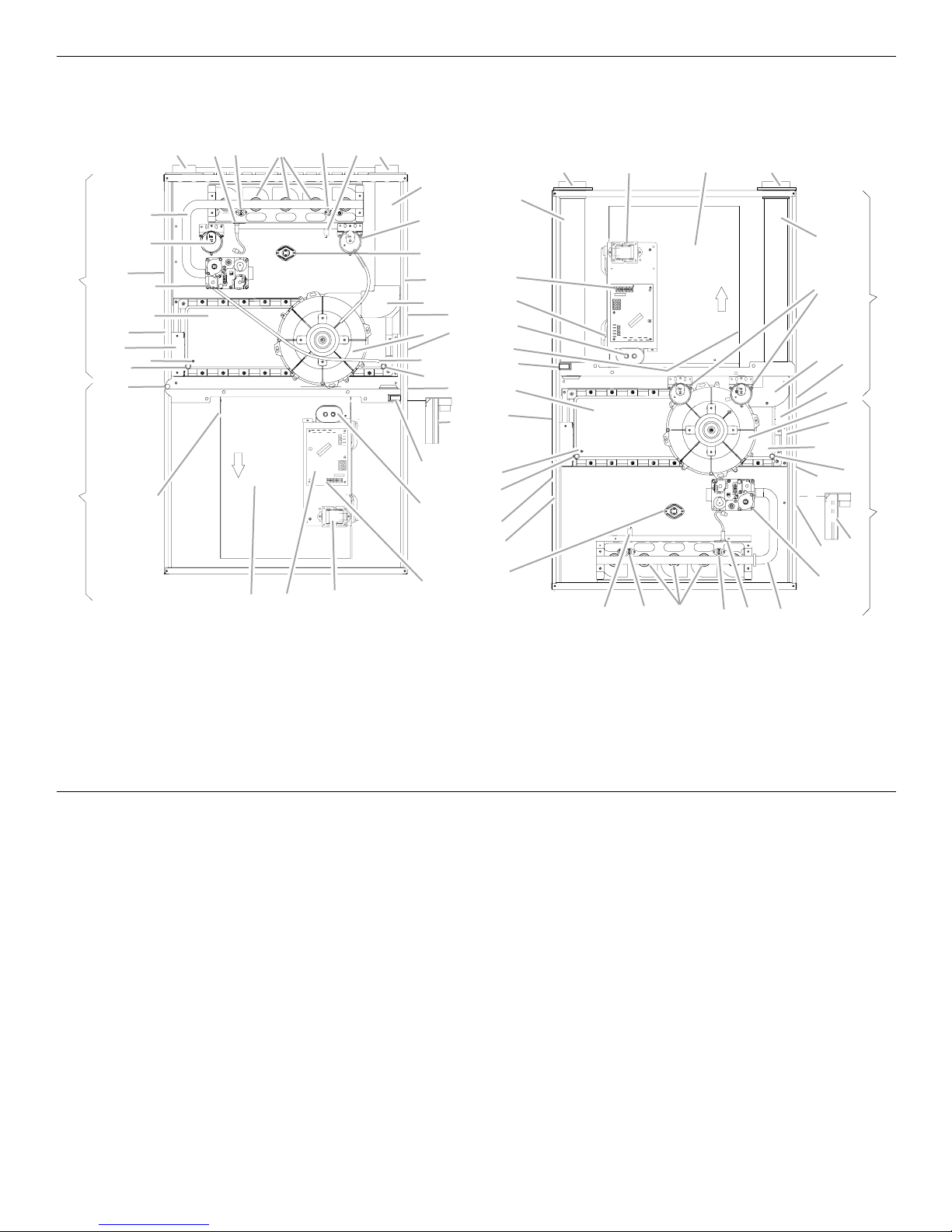
Component Identification
Counterflow/HorizontalUpflow/Horizontal
EFG
D
C
B
A
AE
Burner Compartment
AD
AC
R
S
T
AB
Blower Compartment
*
**
*
*
*
*
*
*
AA
G
H
J
I
EZ AAJ
K
AF
C
K
L
AB
AE
Q
X
W
V
Y
C
O
Blower Compartment
N
AC
P
AD
M
O
N
Q
P
R
S
T
CUTFOR
DEHUM
U
R
V
R
S
S
T
W
T
M
L
X
Y
Z
U
B
A
Burner Compartment
IGHG DF
A. Gas control valve
B. Gas line entrance (alternate)
C. Pressure switch
D. Gas manifold
E. Combustion air intake
connection/coupling
F. Hot surface igniter
G. Rollout limit switch
H. Burners
I. Flame sensor
J. Flue pipe connection/coupling
K. Flue pipe
L. Primary limit switch
M. Gas line entrance
N. Flue pipe connection (alternate)
O. Rubber elbow
P. Induced draft blower
Product Application
This furnace is primarily designed for residential home-heating
applications.
IMPORTANT:
■ This furnace is not designed or certified for use in mobile
homes, trailers or recreational vehicles.
■ This furnace is not designed or certified for outdoor
applications.
■ The furnace must be installed indoors (for example, attic
space, crawl space or garage area provided the garage area
is enclosed with an operating door).
This furnace can be used in the following nonindustrial
commercial applications:
■ Schools
■ Office buildings
■ Churches
■ Retail stores
■ Nursing homes
■ Hotels/motels
■ Common areas
■ Office areas
Q. Electrical connection inlets (alternate)
R. Coil front cover pressure tap
S. Coil front cover drain port
T. Drain line penetrations
U. Drain trap
V. Blower door interlock switch
W. Ca pacito r
X. 24-volt thermostat connections
Y. Integrated control module (with
fuse and diagnostic LED)
Z. Transformer (40VA)
AA. Circulator blower
AB. Auxiliary limit switch
AC. Junction box
AD. Electrical connection inlets
AE. Coil front cover
AF. Combustion air inlet pipe
NOTE: In such applications, the furnace must be installed with
the following stipulations:
■ It must be installed according to the installation instructions
provided and according to local and national codes.
■ It must be installed indoors in a building constructed on site.
■ It must be part of a ducted system and not used in a free air
delivery application.
■ It must not be used as a “makeup” air unit.
■ It must be installed with 2-pipe systems for combustion air,
especially if VOC’s or other contaminants are present in the
conditioned space.
■ All other warranty exclusions and restrictions apply.
5
This furnace is an ETL dual-certified appliance and is appropriate
for use with Natural or propane gas
NOTE: If you are using propane, a propane conversion kit is
required.
Dual certification means that the combustion air inlet pipe is
optional, and the furnace can be vented as a:
■ Nondirect vent (single pipe) central forced air furnace in
which combustion air is taken from the installation area or
from air ducted from the outside or a,
■ Direct vent (dual pipe) central forced air furnace in which all
combustion air supplied directly to the furnace burners
through a special air intake system outlined in these
instructions.
This furnace may be used as a construction site heater only if all
of the following conditions are met:
■ The vent system is permanently installed according to these
installation instructions.
■ A room thermostat is used to control the furnace. Fixed
jumpers that provide continuous heating cannot be used and
can cause long term equipment damage.
■ Return air ducts are provided and sealed to the furnace.
■ A return air temperature range between 60ºF and 80ºF (16ºC
and 27ºC) is maintained.
■ Air filters are installed in the system and maintained during
construction, replaced as appropriate during construction
and upon completion of construction.
■ The input rate and temperature rise are set according to the
furnace rating plate.
■ 100% outside air is provided for combustion air requirements
during construction. Temporary ducting can be used.
NOTE: Do not connect the temporary duct directly to the
furnace. The duct must be sized for adequate combustion
and ventilation in accordance with the latest edition of the
National Fuel Gas Code NFPA 54/ANSI Z223.1 or CAN/CSA
B149.1 Installation Codes.
■ The furnace heat exchanger, components, duct system, air
filters and evaporator coils are thoroughly cleaned following
the final construction cleanup.
■ All furnace operating conditions (including ignition, input rate,
temperature rise and venting) are verified according to these
installation instructions.
NOTE: The Commonwealth of Massachusetts requires that the
following additional requirements must also be met:
■ Gas furnaces must be installed by a licensed plumber or gas
fitter.
■ A T-handle gas cock must be used.
■ If the unit is to be installed in an attic, the passageway to and
the service area around the unit must have flooring.
■ To ensure proper installation and operation, thoroughly read
this manual for specifics pertaining to the installation and
application of this product.
WARNING
Possible property damage, personal injury or death due
to fire, explosion, smoke, soot, condensation, electrical
shock or carbon monoxide may result from improper
installation, repair, operation or maintenance of this
product.
Goodman 48
WARNING
Goodman 49
To prevent property damage, personal injury or death due
to fire, do not install the furnace in a mobile home, trailer
or recreational vehicle.
To ensure proper furnace operation, you must install, operate and
maintain the furnace in accordance with these installation and
operation instructions, all local building codes and ordinances. In
their absence, follow the latest edition of the National Fuel Gas
Code (NFPA 54/ANSI Z223.1), and/or CAN/CSA B149 Installation
Codes, local plumbing or waste water codes and other
applicable codes.
A copy of the National Fuel Gas Code (NFPA 54/ANSI Z223.1)
can be obtained from any of the following:
American National Standards Institute
1430 Broadway
New York, NY 10018
National Fire Protection Association
1 Batterymarch Park
Quincy, MA 02269
CSA International
8501 East Pleasant Valley
Cleveland, OH 44131
A copy of the CAN/CSA B149 Installation Codes can also be
obtained from:
CSA International
178 Rexdale Boulevard
Etobicoke, Ontario, Canada M9W 1R3
The rated heating capacity of the furnace should be greater than
or equal to the total heat loss of the area to be heated. The total
heat loss should be calculated by an approved method or in
accordance with “ASHRAE Guide” or “Manual J-Load
Calculations” published by the Air Conditioning Contractors of
America.
LOCATION REQUIREMENTS AND
CONSIDERATIONS
WARNING
To prevent possible equipment damage, property damage,
personal injury or death, the following bullet points must
be observed when installing the unit.
Follow the instructions listed below when selecting a furnace
location. Refer also to the guidelines provided in “Combustion
and Ventilation Air Requirements.”
■ Centrally locate the furnace with respect to the proposed or
existing air distribution system.
■ Check that the temperature of the return air entering the
furnace is between 55°F and 100°F (13ºC and 38ºC) when the
furnace is heating.
■ Provide provisions for venting combustion products outdoors
through a proper venting system. Special consideration
should be given to the vent/flue pipe routing and the
combustion air intake pipe when applicable. Refer to
“Termination Locations” in “Vent/Flue Pipe and Combustion
Air Pipe” for appropriate termination locations and to
determine if the piping system from the furnace to the
termination can be accomplished within the guidelines given.
NOTE: The length of flue and/or combustion air piping can be
a limiting factor in the location of the furnace.
Goodman 50
6
■ Locate the furnace so that the condensate flows downward
to the drain.
NOTE: Do not locate the furnace or its condensate drainage
system in any area subject to below freezing temperatures
without the proper freeze protection. Refer to “Condensate
Drain Lines and Trap” for further details.
■ Check that adequate combustion air is available for the
furnace. Improper or insufficient combustion air can expose
building occupants to gas combustion products that could
include carbon monoxide. Refer to “Combustion and
Ventilation Air Requirements.”
■ Set the furnace on a level floor to enable proper condensate
drainage. If the floor becomes wet or damp at times, place
the furnace above the floor on a concrete base sized
approximately 1¹⁄₂" (3.8 cm) larger than the base of the
furnace. Refer to “Horizontal Applications and
Considerations” for leveling of horizontal furnaces.
■ Check that the upflow or horizontal furnaces are not installed
directly on carpeting, or any other combustible material.
NOTE: The only combustible material allowed is wood.
■ A special accessory subbase must be used for the upright
counterflow unit installations over any combustible material
(including wood). Refer to subbase instructions for installation
details.
NOTE: A subbase will not be required if an air conditioning
coil is located beneath the furnace between the supply air
opening and the combustible floor.
■ Exposure to contaminated combustion air will result in safety
and performance-related problems.
NOTE: Do not install the furnace where the combustion air is
exposed to the following substances:
Chlorinated waxes or cleaners
Chlorine-based swimming pool chemicals
Water softening chemicals
Deicing salts or chemicals
Carbon tetrachloride
Halogen-type refrigerants
Cleaning solutions (such as perchloroethylene)
Printing inks
Paint removers
Var nishes
Hydrochloric acid
Cements and glues
Antistatic fabric softeners for clothes dryers
Masonry acid washing materials
■ Seal off a nondirect vent furnace if it is installed near an area
frequently contaminated by any of the above substances.
This protects the nondirect vent furnace from airborne
contaminants. To ensure that the enclosed nondirect vent
furnace has an adequate supply of combustion air, vent from
a nearby uncontaminated room or from outdoors. Refer to
“Combustion and Ventilation Air Requirements” for details.
■ If the furnace is used in connection with a cooling coil unit,
install the furnace upstream or in parallel with the cooling coil
unit. Premature heat exchanger failure will result if the cooling
coil unit is placed ahead of the furnace.
■ If the furnace is installed in a residential garage, position the
furnace so that the burners and ignition source are located
not less than 18" (45.7 cm) above the floor. Protect the
furnace from physical damage by vehicles.
■ If the furnace is installed horizontally, ensure the furnace
access doors are not on the “up/top” or “down/bottom” side
of the furnace. The furnace access doors must be vertical so
that the burners fire horizontally into the heat exchanger.
■ Do not connect the furnace to a chimney flue that serves a
separate appliance designed to burn solid fuel.
■ On counterflow installations, the air conditioning coil must be
downstream on the supply (positive) side of the furnace heat
exchanger.
Counterflow Installation Over a Noncombustible Floor
■ Before setting the furnace over the plenum opening, ensure
that the surface around the opening is smooth and level. A
tight seal should be made between the furnace base and
floor by using a silicone rubber caulking compound or
cement grout.
Counterflow Installation Over a Combustible Floor
■ If installation over a combustible floor becomes necessary,
use an accessory subbase (see Specification Sheet
applicable for your model for details). A special accessory
subbase must be used for upright counterflow unit
installations over any combustible material including wood.
Refer to subbase instructions for installation details. Follow
the instructions with the subbase for proper installation.
NOTES:
■ Do not install the furnace directly on carpeting, tile or
other combustible material other than wood flooring.
■ The subbase will not be required if an air conditioning coil
is installed between the supply air opening on the furnace
and the floor.
Clearances and Accessibility
Installations must adhere to the clearances to combustible
materials to which this furnace has been design-certified. The
minimum clearance information for this furnace is provided on
the unit’s clearance label. These clearances must be permanently
maintained.
Clearances must also accommodate an installation’s gas,
electrical, drain trap and drain line connections. If the alternate
vent/flue connection is used, additional clearance must be
provided to accommodate these connections. Refer to “Vent/
Flue Pipe and Combustion Air Pipe” for details.
NOTE: In addition to the required clearances to combustible
materials, a minimum of 24" (61 cm) service clearance must be
available in front of the unit.
A
B
BB
Upflow Counterflow Horizontal
C
A. Top
B. Side
C. Bottom
A furnace installed in a confined space (for example, a closet or
utility room) must have 2 ventilation openings with a total
minimum free area of 0.25 sq. in. per 1,000 Btu/h of furnace input
rating. Refer to the Specification Sheet applicable to your model
for minimum clearances to combustible surfaces. One of the
ventilation openings must be within 12" (30.5 cm) of the top. The
other opening must be within 12" (30.5 cm) of the bottom of the
confined space. In a typical construction, the clearance between
the door and door frame is usually adequate to satisfy this
ventilation requirement.
A
C
7
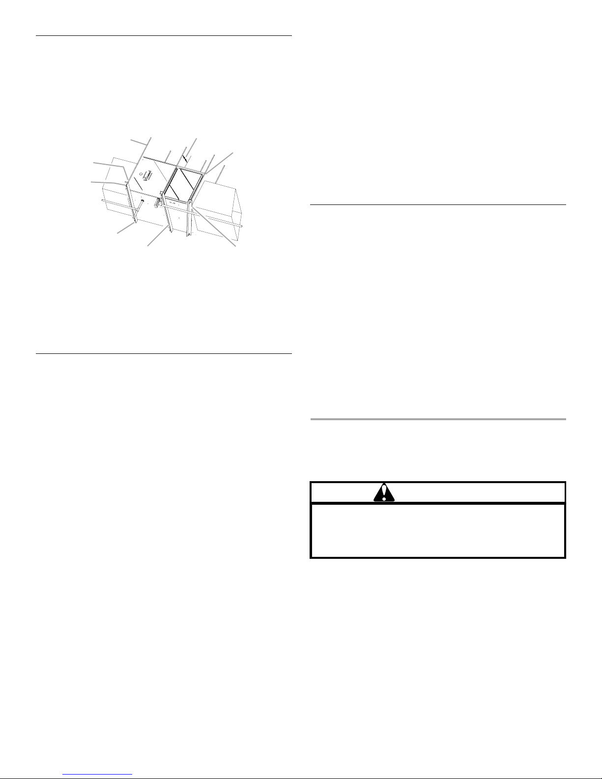
Furnace Suspension
If suspending the furnace from rafters or joists, use ³⁄₈" threaded
rod and 2" x 2" x ¹⁄₈" (5.1 cm x 5.1 cm x 3.2 mm) angle iron as
shown in “Suspended Furnace” illustration. The length of rod will
depend on the application and the clearances necessary.
Suspended Furnace
A
H
G
F
A.
³⁄₈
" (1 cm) diameter threaded
rod (6)
B. 8" (20.3 cm) minimum clearance
between center rod and furnace
cabinet to allow for circulator
blower removal.
C. Level furnace end to end, slight
forward tilt with front 0" to
(1.9 cm) below back.
³⁄₄
"
B
C
DE
D. Tilt outward to allow for door
and circulator blower removal.
E. Position as close as possible to
blower deck to allow for
circulator blower removal.
F. 2" x 2" x
3.2 mm) angle iron (3)
G. Support nuts
H. Hold down nuts
¹⁄₈
" (5.1 cm x 5.1 cm x
Existing Furnace Removal
NOTE: When an existing furnace is removed from a venting
system serving other appliances, the venting system may be too
large to properly vent the remaining attached appliances.
The following vent testing procedure is reproduced from the
American National Standard/National Standard of Canada for
Gas-Fired Central Furnaces ANSI Z21.47—latest edition,
CSA-2.3 latest edition Section 1.23.1.
The following steps shall be followed with each appliance
connected to the venting system placed in operation, while any
other appliances connected to the venting system are not in
operation:
1. Seal any unused openings in the venting system.
2. Inspect the venting system for proper size and horizontal
pitch, as required by the National Fuel Gas Code, ANSI
Z223.1 or the Natural Gas and Propane Installation Code,
CSA B149.1-05 and these instructions. Determine that there
is no blockage or restriction, leakage, corrosion and other
deficiencies which could cause an unsafe condition.
3. As far as practical, close all building doors and windows and
all doors between the space in which the appliance(s)
connected to the venting system are located and other
spaces of the building.
4. Close fireplace dampers.
5. Turn on clothes dryers and any appliance not connected to
the venting system. Turn on any exhaust fans, such as range
hoods and bathroom exhausts, so they shall operate at
maximum speed. Do not operate a summer exhaust fan.
6. Follow the lighting instructions. Place the appliance being
inspected in operation. Adjust thermostat so appliance shall
operate continuously.
7. Test for spillage from draft hood appliances at the draft hood
relief opening after 5 minutes of main burner operation. Use
the flame of a match or candle.
8. After it has been determined that each appliance connected
to the venting system properly vents when tested as outlined
above, return doors, windows, exhaust fans, fireplace
dampers and any other gas-burning appliance to their
previous conditions of use.
9. If improper venting is observed during any of the above tests,
the venting system must be corrected in accordance with the
National Fuel Gas Code ANSI Z223.1/NFPA 54 and/or
National Gas and Propane Installation Code CSA B149.1-05.
If resizing is required on any portion of the venting system, use
the appropriate table in Appendix G in the latest edition of the
National Fuel Gas Code ANSI Z223.1 and/or National Gas and
Propane Installation Code CSA B149.1-05.
Thermostat Location
The thermostat should be placed approximately 5 ft (1.5 m) from
the floor on a vibration-free, inside wall in an area having good air
circulation.
NOTE: Do not install the thermostat where it may be influenced
by any of the following:
■ Drafts, or dead spots behind doors, in corners or under
cabinets
■ Hot or cold air from registers
■ Radiant heat from the sun
■ Light fixtures or other appliances
■ Radiant heat from a fireplace
■ Concealed hot or cold water pipes or chimneys
■ Unconditioned areas behind the thermostat, such as an
outside wall
Consult the instructions packaged with the thermostat for
mounting instructions and further precautions.
COMBUSTION AND VENTILATION
AIR REQUIREMENTS
WARNING
To avoid property damage, personal injury or death,
sufficient fresh air for proper combustion and ventilation
of flue gases must be supplied. Most homes require
outside air be supplied into the furnace area.
Improved construction and additional insulation in buildings have
reduced heat loss by reducing air infiltration and escape around
doors and windows. These changes have helped in reducing
heating/cooling costs but have created a problem supplying
combustion and ventilation air for gas-fired and other
fuel-burning appliances.
Appliances that pull air out of the house (clothes dryers, exhaust
fans, fireplaces, etc.) increase the problem by starving appliances
for air.
Goodman 51
8
House depressurization can cause back drafting or improper
B
B
combustion of gas-fired appliances, thereby exposing building
occupants to gas combustion products that could include carbon
monoxide.
If this furnace is to be installed in the same space with other gas
appliances, such as a water heater, ensure there is an adequate
supply of combustion and ventilation air for the other appliances.
Refer to the latest edition of the National Fuel Gas Code NFPA
54/ANSI Z223.1 or CAN/CSA B149 Installation Codes or
applicable provisions of the local building codes for determining
the combustion air requirements for the appliances.
Most homes will require outside air to be supplied to the furnace
area by means of ventilation grilles or ducts connecting directly
to the outdoors or spaces open to the outdoors such as attics or
crawl spaces.
The following information on air for combustion and ventilation is
reproduced from the National Fuel Gas Code NFPA 54/ANSI
Z223.1 Section 5.3.
5.3.1 General:
a) The provisions of 5.3 apply to gas utilization equipment
installed in buildings and which require air for
combustion, ventilation and dilution of flue gases from
within the building. They do not apply to (1) direct vent
equipment which is constructed and installed so that all
air for combustion is obtained from the outside
atmosphere and all flue gases are discharged to the
outside atmosphere, or (2) enclosed furnaces which
incorporate an integral total enclosure and use only
outside air for combustion and dilution of flue gases.
b) Equipment shall be installed in a location in which the
facilities for ventilation permit satisfactory combustion of
gas, proper venting and the maintenance of ambient
temperature at safe limits under normal conditions of use.
Equipment shall be located so as not to interfere with
proper circulation of air. When normal infiltration does not
provide the necessary air, outside air shall be introduced.
c) In addition to air needed for combustion, process air shall
be provided as required for: cooling of equipment or
material, controlling dew point, heating, drying, oxidation
or dilution, safety exhaust, odor control and air for
compressors.
d) In addition to air needed for combustion, air shall be
supplied for ventilation, including all the air required for
comfort and proper working conditions for personnel.
e) While all forms of building construction cannot be
covered in detail, air for combustion, ventilation and
dilution of flue gases for gas utilization equipment vented
by natural draft normally may be obtained by application
of one of the methods covered in 5.3.3 and 5.3.4.
f) Air requirements for the operation of exhaust fans,
kitchen ventilation systems, clothes dryers and fireplaces
shall be considered in determining the adequacy of a
space to provide combustion air requirements.
5.3.2 Equipment Located in Unconfined Spaces:
In unconfined spaces (see definition below) in buildings,
infiltration may be adequate to provide air for combustion
ventilation and dilution of flue gases. However, in buildings of
tight construction (for example, weather stripping, heavily
insulated, caulked, vapor barrier, etc.), additional air may need to
be provided using the methods described in 5.3.3-b or 5.3.4.
Space, Unconfined.
For purposes of this Code, a space whose volume is not less
than 50 cu ft per 1,000 Btu/h of the aggregate input rating of all
appliances installed in that space. Rooms communicating
directly with the space in which the appliances are installed
through openings not furnished with doors, are considered a part
of the unconfined space.
5.3.3 Equipment Located in Confined Spaces:
a) All Air from Inside the Building: The confined space shall
be provided with 2 permanent openings communicating
directly with an additional room(s) of sufficient volume so
that the combined volume of all spaces meets the criteria
for an unconfined space. The total input of all gas
utilization equipment installed in the combined space
shall be considered in making this determination. Each
opening shall have a minimum free area of 1 sq. in.
(6.5 cm2) per 1,000 Btu/h of the total input rating of all gas
utilization equipment in the confined space, but not less
than 100 sq. in (645.2 cm2). One opening shall be within
12" (30.5 cm) of the top and one within 12" (30.5 cm) of
the bottom of the enclosure.
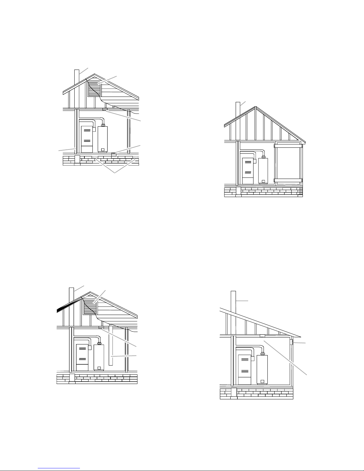
Equipment Located in Confined Spaces: All Air from Inside
Building. See 5.3.3-a.
NOTE: Each opening must have a free area of not less than
1 sq. in. (6.5 cm
equipment in the enclosure, but not less than 100 sq. in.
(645.2 cm
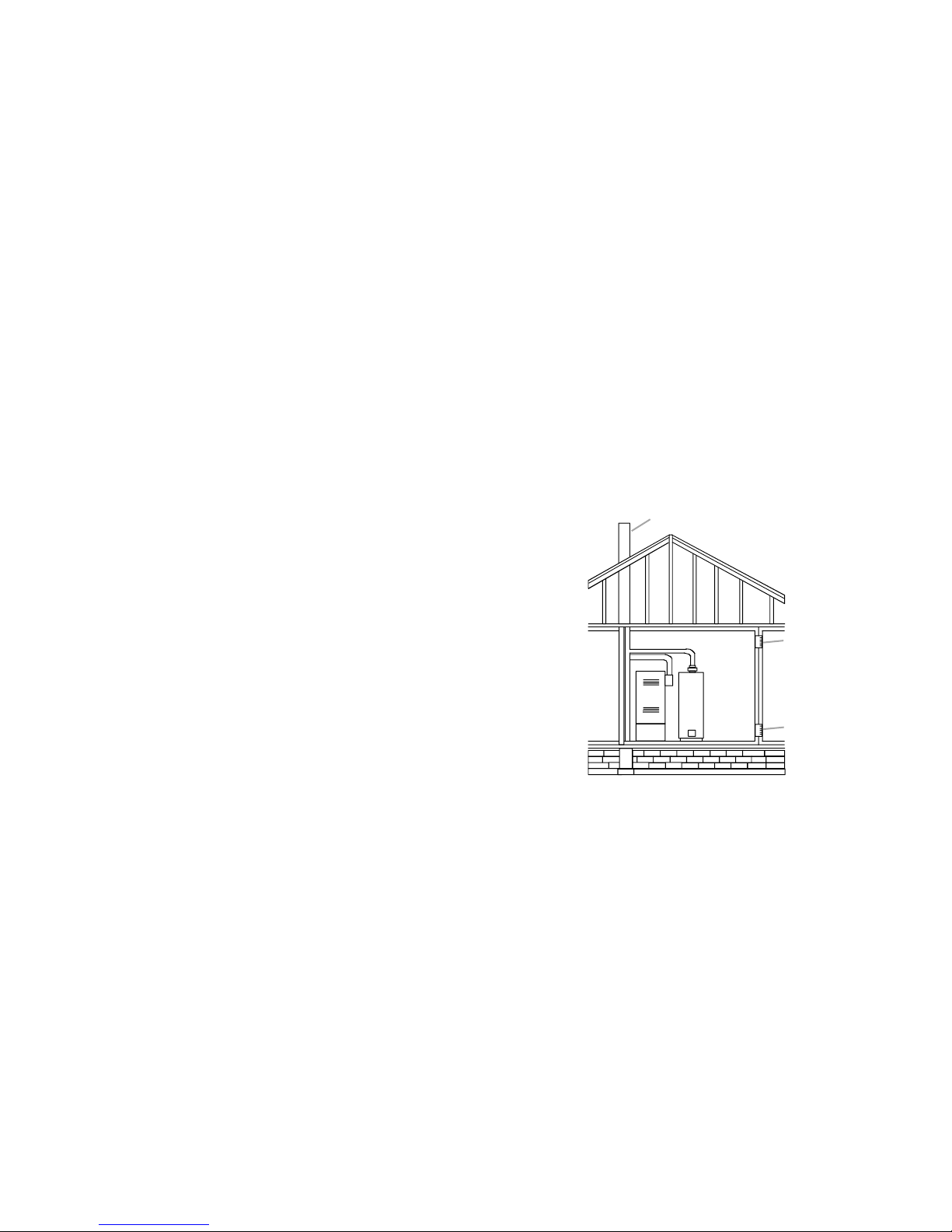
b) All Air from Outdoors: The confined space shall be
provided with 2 permanent openings, one commencing
within 12" (30.5 cm) of the top and one commencing
within 12" (30.5 cm) of the bottom of the enclosure. The
openings shall communicate directly, or by ducts, with
the outdoors or spaces (crawl or attic) that freely
communicate with the outdoors.
1. When directly communicating with the outdoors, each
2
) per 1,000 Btu of the total input rating of all
2
).
A
CD
A. Chimney or gas vent
B. Opening(s)
opening shall have a minimum free area of 1 sq. in.
2
(6.5 cm
) per 4,000 Btu/h of total input rating of all
C. Water heater
D. Furnace
equipment in the enclosure.
9
Equipment Located in Confined Spaces: All Air from
C
D
C
D
C
Outdoors—Inlet Air from Ventilated Crawl Space and
Outlet Air to Ventilated Attic. See 5.3.3-b.
NOTE: The inlet and outlet air openings must each have a free
area of not less than 1 sq. in. (6.5 cm
input rating of all equipment in the enclosure.
A
2
) per 4,000 Btu of the total
B
FG
Equipment Located in Confined Spaces: All Air from
Outdoors. See 5.3.3-b.
NOTES:
■ The air duct openings must each have a free area of not less
than 1 sq. in. (6.5 cm
of all equipment in the enclosure.
■ If the appliance room is located against an outside wall and
the air openings communicate directly with the outdoors,
each opening shall have a free area of not less than 1 sq. in.
(6.5 cm
2
) per 4,000 Btu/h of the total input rating of all
appliances in the enclosure.
2
) per 2,000 Btu of the total input rating
A
H
E
A. Chimney or gas vent
B. Ventilation louvers
(each end of attic)
C. Outlet air
D. Inlet air
E. Ventilation louvers for
unheated crawl space
F. Wa te r h ea ter
G. Furnace
H. Alternate air inlet
2. When communicating with the outdoors through vertical
ducts, each opening shall have a minimum free area of
1 sq. in. (6.5 cm
2
) per 4,000 Btu/h of total input rating of
all equipment in the enclosure.
Equipment Located in Confined Spaces: All Air from
Outdoors Through Ventilated Attic. See 5.3.3-b.
NOTE: The inlet and outlet air openings must each have a free
area of not less than 1 sq. in. (6.5 cm2) per 4,000 Btu of the total
input rating of all equipment in the enclosure.
A
B
B
DE
C
A. Chimney or gas vent
B. Outlet air duct
C. Inlet air duct
D. Water heater
E. Furnace
4. When ducts are used, they shall be of the same cross-
sectional area as the free area of the openings to which
they connect. The minimum dimension of rectangular air
ducts shall not be less than 3" (7.6 cm).
Equipment Located in Confined Spaces: All Air from
Outdoors—Single Air Opening. See 5.3.3-b.
NOTE: The single opening must each have a free area of not less
than 1 sq. in. (6.5 cm
equipment in the enclosure, but not less than the sum of the
areas of all vent connectors in the confined space.
2
) per 3,000 Btu of the total input rating of all
A
EF
A. Chimney or gas vent
B. Ventilation louvers
(each end of attic)
C. Outlet air
D. Inlet air duct (ends 12"
[30.5 cm] above floor)
E. Water heater
F. Fu r n a c e
3. When communicating with the outdoors through
horizontal ducts, each opening shall have a minimum free
area of 1 sq. in. (6.5 cm2) per 2,000 Btu/h of total input
rating of all equipment in the enclosure.
10
B
DE
A. Chimney or gas vent
B. Opening
C. Alternate opening location
D. Water heater
E. Furnace
5. When directly communicating with the outdoors, the
single opening shall have a minimum free area of 1 sq. in.
2
(6.5 cm
) per 3,000 Btu/h of total input rating of all
equipment in the enclosure.
5.3.4 Specially Engineered Installations:
D
The requirements of 5.3.3 shall not necessarily govern when
special engineering, approved by the authority having
jurisdiction, provides an adequate supply of air for combustion,
ventilation, and dilution of flue gases.
■ Alternate electrical and gas line connections
■ Drain pan
■ Freeze protection
■ Furnace suspension.
5.3.5 Louvers and Grilles:
In calculating free area in 5.3.3, consideration shall be given to
the blocking effect of louvers, grilles or screens protecting
openings. Screens used shall not be smaller than ¹⁄₄" (6.4 mm)
mesh. If the area through a design of louver or grille is known, it
should be used in calculating the size of opening required to
provide the free area specified. If the design and free area is not
known, it may be assumed that wood louvers will have 20 to
25 percent free area and metal louvers and grilles will have 60 to
75 percent free area. Louvers and grilles shall be fixed in the open
position or interlocked with the equipment so that they are
opened automatically during equipment operation.
5.3.6 Special Conditions Created by Mechanical
Exhausting or Fireplaces:
Operation of exhaust fans, ventilation systems, clothes dryers or
fireplaces may create conditions requiring special attention to
avoid unsatisfactory operation of installed gas utilization
equipment. Air from Inside Building. See 5.3.3-a.
INSTALLATION POSITIONS
This furnace may be installed in an upright position or horizontal
on either the left or right side panel.
NOTE: Do not install this furnace on its back.
For upright upflow furnaces, the return air ductwork may be
attached to the side panel(s) and/or base pan.
For horizontal upflow furnaces, the return air ductwork must be
attached to the base pan.
For both the upright or horizontal counterflow furnaces, the
return air ductwork must be attached to the base pan (top end of
the blower compartment).
NOTE: Do not attach the ductwork to the back of the furnace.
For upflow installations requiring 1,800 CFM or more, use either
2 side returns or a bottom return or a combination of side and
bottom.
Contact your local distributor for the proper airflow requirements
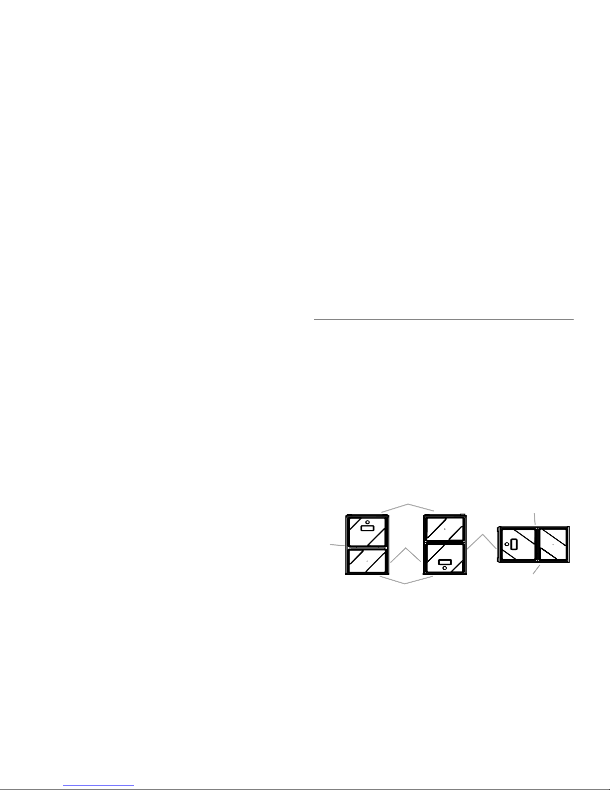
and the number of required ductwork connections. See the
“Recommended Installation Positions” illustrations for the
appropriate installation positions, ductwork connections and the
resulting airflow
HORIZONTAL APPLICATIONS
AND CONSIDERATIONS
General
Horizontal applications, in particular, may dictate many of the
installation’s specifics such as airflow direction, ductwork
connections, flue and combustion air pipe connections, etc. The
basic application of this furnace as a horizontal furnace differs
only slightly from an upright installation.
When installing a furnace horizontally, additional consideration
must be given to the following:
■ Drain trap and lines
■ Leveling the furnace
■ Alternate vent/flue and combustion air connections
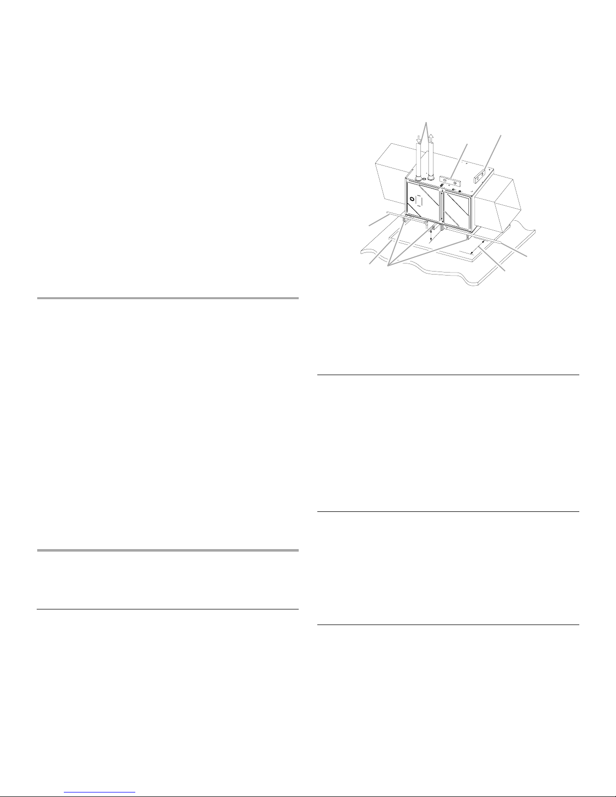
Horizontal Furnace
A
C
E
I
H
G
A. Alternate vent/flue location
B. Level end-to-end
C. Level side-to-side or slightly
tilted—doors 0" to
below back panel
¹⁄₄
D. Drain line—
foot downward slope
" (6.4 mm) per
³⁄₄
" (1.9 cm)
F
B
E. 36" (91.4 cm) minimum service
clearance
F. 4
³⁄₄
" (12.1 cm) minimum drain trap
clearance
G. Supports at both ends and middle
H. Drain pan
I. Gas line with 3" (7.6 cm) minimum
drip leg
Drain Trap and Lines
In horizontal applications, the condensate drain trap is secured to
the furnace side panel, suspending it below the furnace. A
minimum clearance of 4³⁄₄" (12.1 cm) below the furnace must be
provided for the drain trap.
Additionally, the appropriate downward piping slope must be
maintained from the drain trap to the drain location.
Refer to “Condensate Drain Trap and Lines” for further details. If
the drain trap and drain line will be exposed to temperatures near
or below freezing, adequate measures must be taken to avoid
condensate from freezing.
Leveling
Leveling ensures proper condensate drainage from the heat
exchanger and induced draft blower. For proper flue pipe
drainage, the furnace must be level lengthwise from end to end.
The furnace should also be level from back to front, or have a
slight tilt with the access doors sloping downward ³⁄₄" (1.9 cm)
lower than the back panel. The slight tilt allows the heat
exchanger condensate, generated in the recuperator coil, to flow
forward to the recuperator coil front cover.
Alternate Vent/Flue Connections
In horizontal installations, provisions for alternate vent/flue piping
are available for upflow furnaces with left discharge and
counterflow furnaces with right air discharge. This configuration
allows the vent/flue and combustion air piping to be run vertically
through the side of the furnace. Refer to the “Recommended
Installation Positions” illustrations for further details. The
standard piping connections may also be used in these positions.
See “Vent/Flue Pipe and Combustion Air Pipe” for details
concerning the conversion to the alternate vent/flue connections.
11
When using the horizontal alternate vent configuration, you must
B
C
B
use the RF000142 vent drain kit. See “Alternate Flue/Vent
Location” illustration.
NOTE: Alternate vertical piping connections cannot be used
when an upflow furnace is installed with the supply air
discharging to the right, or when a counterflow furnace is
installed with the supply air discharging to the left. In either case,
use the standard flue and combustion air piping connections.
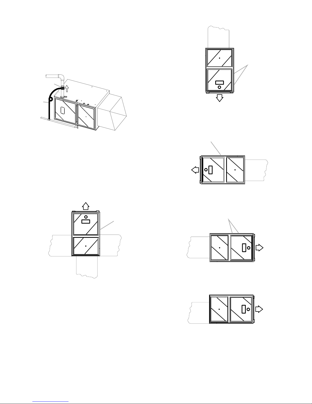
Alternate Flue/Vent Location
A
B
Recommended Installation Positions—Upright Counterflow
A
C
A. Vent/Drain
B. Airflow
C. Field supplied drain hose
NOTES:
■ The field supplied drain hose is connected from the vent/
drain connection to the condensate drain line with a field
supplied connector.
■ Make a small loop in the drain hose to serve as a P-trap.
Recommended Installation Positions—Upright Upflow
A
B
CC
C
A. Bottom return duct connection
B. Alternate flue and combustion air pipe locations
C. Air discharge
Recommended Installation Positions—Horizontal
Upflow—Left Side Panel Discharge
B
A
A. Air discharge
B. Alternate flue pipe location
C. Bottom return duct connection
C
Recommended Installation Positions—Horizontal
Counterflow—Right Side Panel Discharge
B
A
D
A. Air discharge
B. Alternate flue pipe location
C. Side return duct connections
D. Bottom return duct connection
12
A. Bottom return duct connection
B. Alternate flue pipe location
C. Air discharge
Recommended Installation Positions—Horizontal
Upflow—Right Side Panel Discharge
A
A. Bottom return duct connection
B. Air discharge
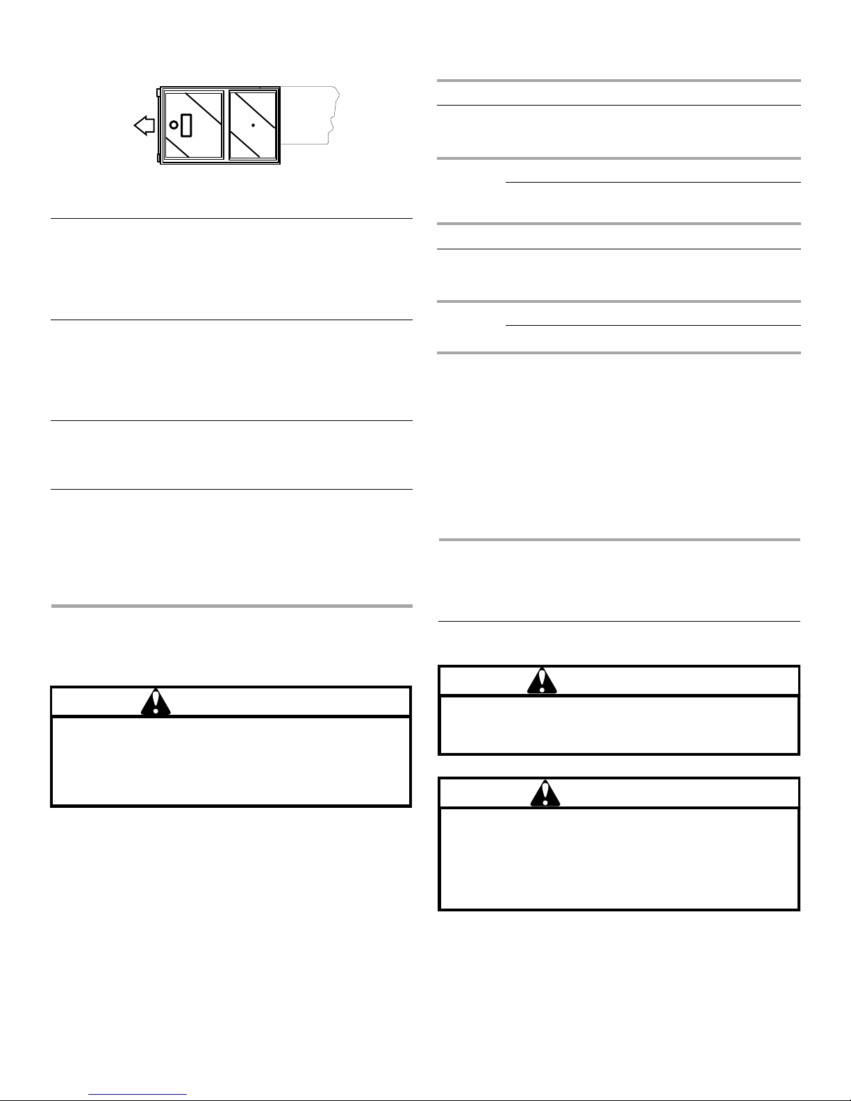
Recommended Installation Positions—Horizontal
Counterflow—Left Side Panel Discharge
For installations above 7,000 ft (2,133.6 m), refer to your
distributor for required kit(s).
WFD19, WGFM19, WGFM29, WGFD29 Gas Orifice Chart
A
A. Air discharge
B. Bottom return duct connection
B
Alternate Electrical and Gas Line Connections
This furnace has provisions allowing for electrical and gas line
connections through either side panel.
In horizontal applications, the connections can be made either
through the top or bottom of the furnace.
Drain Pan
A drain pan must be provided if the furnace is installed above a
conditioned area.
The drain pan must cover the entire area under the furnace (and
air conditioning coil, if applicable).
Freeze Protection
Refer to “Horizontal Applications and Conditions—Drain Trap and
Lines.”
Furnace Suspension
If the furnace is installed in a crawl space, it must be suspended
from the floor joist or supported by a concrete pad.
NOTE: Never install the furnace on the ground or allow it to be
exposed to water. Refer to “Location Requirements and
Considerations—Furnace Suspension” for further details.
Pressure
Altitude Gas Kit Orifice
0 to
7,000 ft
(2,133.6 m)
WFM19 Gas Orifice Chart
Altitude Gas Kit Orifice
0 to
7,000 ft
(2,133.6 m)
NOTES:
■ In Canada, gas furnaces are only certified to 4,500 ft
(1,371.6 m).
■ LPM-05 supports White-Rodgers 2-stage valve only.
■ LPM-06 supports both Honeywell and White-Rodgers
2-stage valves.
Contact the distributor for a tabular listing of appropriate
manufacturer’s kits for propane gas and/or high altitude
installations. The indicated kits must be used to insure proper
furnace operation. All conversions must be performed by a
qualified installer or service agency.
Natural None #43 3.5" W.C. None
Propane LPM-05
LPM-06
Natural None #45 3.5" W.C. None
Propane LPM-06 #55 10.0" W.C. None
#55 10.0" W.C. None
Manifold
Pressure
Manifold
Pressure
Switch
Change
Pressure
Switch
Change
VENT/FLUE PIPE AND
COMBUSTION AIR PIPE
PROPANE GAS/HIGH ALTITUDE
INSTALLATIONS
WARNING
Possible property damage, personal injury or death may
occur if the correct conversion kits are not installed. The
appropriate kits must be applied to ensure safe and proper
furnace operation. All conversions must be performed by
a qualified installer or service agency.
This furnace is shipped from the factory configured for Natural
gas at standard altitude. Propane gas installations require an
orifice change to compensate for the energy content difference
between Natural and propane gas.
High altitude installations may require both a pressure switch and
an orifice/spring change. These changes are necessary to
compensate for the natural reduction in the density of both the
gas fuel and the combustion air at higher altitude.
Goodman 52
Failure to follow these instructions can result in bodily
injury or death. Carefully read and follow all instructions
given in this section.
Upon completion of the furnace installation, carefully
inspect the entire flue system both inside and outside of
the furnace to assure it is properly sealed. Leaks in the
flue system can result in serious personal injury or death
due to exposure to flue products, including carbon
monoxide.
A condensing gas furnace achieves its high level of efficiency by
extracting almost all of the heat from the products of combustion
and cooling them to the point where condensation takes place.
Because of the relatively low flue gas temperature and water
condensation requirements, PVC pipe is used as venting
material.
General
WARNING
Goodman 53
WARNING
Goodman 54
13
NOTES:
■ This furnace must not be connected to Type B, BW, or L vent
or vent connector, and must not be vented into any portion of
a factory-built or masonry chimney except when used as a
pathway for PVC as described later in this section.
■ Do not common vent this appliance with another appliance or
use a vent which is used by a solid fuel appliance.
■ Do not use commercially available “no hub connectors” other
than those shipped with this product.
It is the responsibility of the installer to follow the manufacturers’
recommendations and to verify that all vent/flue piping and
connectors are compatible with furnace flue products.
Additionally, it is the responsibility of the installer to ensure that all
piping and connections possess adequate structural integrity and
support to avoid flue pipe separation, shifting or sagging during
furnace operation.
Dual Certification: Nondirect/Direct Vent
This furnace is dual certified and may be installed as a nondirect
vent (single pipe) or direct vent (dual pipe) appliance. A nondirect
vent installation requires only a vent/flue pipe, while a direct vent
installation requires both a vent/flue pipe and a combustion air
intake pipe. Refer to the appropriate section for details
concerning piping size, length, number of elbows, furnace
connections and terminations.
Materials and Joining Methods
WARNING
To avoid bodily injury, fire or explosion, solvent cements
must be kept away from all ignition sources (for example,
sparks, open flames and excessive heat) as they are
combustible liquids. Avoid breathing cement vapors or
contact with skin and/or eyes.
2" or 3" (5.1 cm or 7.6 cm) nominal diameter PVC Schedule
40 pipe meeting ASTM D1785, PVC primer meeting ASTM F656
and PVC solvent cement meeting ASTM D2564 specifications
must be used. Fittings must be DWV type fittings meeting ASTM
D2665 and ASTM D3311. Carefully follow the pipe
manufacturer’s instructions for cutting, cleaning and solvent
cementing of PVC.
The use of Schedule 40 PVC Cellular Core (Foam Core) plastic
pipe is also acceptable as a flue/vent and intake pipe material.
PVC primer meeting ASTM F656 and PVC solvent cement
meeting ASTM D2564 specifications must be used. Fittings must
be DWV type fittings meeting ASTM D2665 and ASTM D3311.
Carefully follow the pipe manufacturer’s instructions for cutting,
cleaning and solvent cementing of PVC.
As an alternative to PVC pipe, primer, solvent cement and fittings,
ABS materials which are in compliance with the following
specifications may be used. 2" or 3" (5.1 cm or 7.6 cm) ABS
Schedule 40 pipe must meet ASTM D1527 and, if used in
Canada, must be CSA approved. Solvent cement for ABS to ABS
joints must meet ASTM D2235 and, if used in Canada, must be
CSA approved. The solvent cement for the PVC to ABS transition
joint must meet ASTM D3138. Fittings must be DWV type fittings
meeting ASTM D2661 and ASTM D3311 and, if used in Canada,
must be CSA approved. Carefully follow the manufacturer’s
instructions for cutting, cleaning, and solvent cementing PVC
and/or ABS.
Goodman 55
All 90° elbows must be medium-radius (¹⁄₄ bend DWV) or
long-radius (long sweep ¹⁄₄ bend DWV) types conforming to
ASTM D3311. A medium-radius (¹⁄₄ bend DWV) elbow measures
3¹⁄₁₆" (7.8 cm) minimum from the plane of one opening to the
centerline of the other opening for 2" (5.1 cm) diameter pipe, and
4⁹⁄₁₆" (11.6 cm) minimum for 3" (7.6 cm) pipe.
Proper Vent/Flue and Combustion Air
Piping Practices
Adhere to these instructions to ensure safe and proper furnace
performance. The length, diameter and number of elbows of the
vent/flue pipe and combustion air pipe (when applicable) affects
the performance of the furnace and must be carefully sized. All
piping must be installed in accordance with local codes and
these instructions.
Piping must be adequately secured and supported to prohibit
sagging, joint separation and/or detachment from the furnace.
Horizontal runs of vent/flue piping must be supported every 36"
to 60" (91.4 cm to 1.5 m) and must maintain a ¹⁄₄" (6.4 mm) per
foot downward slope, back toward the furnace, to properly return
condensate to the furnace’s drain system. Allowances should be
made for minor expansion and contraction due to temperature
variations. For this reason, particular care must be taken to
secure piping when a long run is followed by a short offset of less
than 40" (101.6 cm).
Precautions should be taken to prevent condensate from freezing
inside the vent/flue pipe and/or at the vent/flue pipe termination.
All vent/flue piping exposed to freezing temperatures below 35°F
(2ºC) for extended periods of time must be insulated with ¹⁄₂"
(1.3 cm) thick closed-cell foam. Also all vent/flue piping exposed
outdoors in excess of the terminations shown in this manual (or in
unheated areas) must be insulated with ¹⁄₂" (1.3 cm) thick
closed-cell foam. Inspect piping for leaks prior to installing
insulation.
Termination Locations
NOTE: Refer to “Location Requirements and Considerations” for
combustion air contaminant restrictions.
The following bullets and illustration describe the restrictions
concerning the appropriate location of vent/flue pipe and
combustion air intake pipe (when applicable) terminations. Refer
to “Nondirect Vent (Single Pipe) Piping and Direct Vent (Dual
Pipe) Piping” located in this section for specific details on
termination construction.
■ All terminations (flue and/or intake) must be located at least
12" (30.5 cm) above ground level or the anticipated snow
level.
■ Vent terminations (nondirect and direct vent) must terminate
at least 36" (91.4 cm) above any forced air inlet located within
10 ft (3 m).
NOTE: This provision does not apply to the combustion air
intake termination of a direct vent application.
■ The vent termination of a nondirect vent application must
terminate at least 48" (121.9 cm) below, 48" (121.9 cm)
horizontally from or 12" (30.5 cm) above any door, window or
gravity air inlet into any building.
■ The vent termination of a direct vent application must
terminate at least 12" (30.5 cm) from any opening through
which flue gases may enter a building (door, window or
gravity air inlet).
14
■ The vent termination of vent pipe run vertically through a roof
must terminate at least 12" (30.5 cm) above the roof line (or
the anticipated snow level) and be at least 12" (30.5 cm) from
any vertical wall (including any anticipated snow buildup).
■ A vent termination shall not terminate over public walkways
or over an area where condensate or vapor could create a
nuisance or hazard or could be detrimental to the operation
of regulators, relief valves or other equipment.
■ The combustion air intake termination of a direct vent
application should not terminate in an area which is
frequently dusty or dirty.
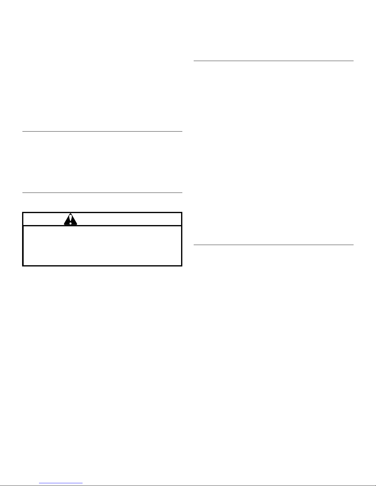
Vent Termination Clearances
A
Vent/Flue Pipe
Vent/flue pipe can be secured to the vent/flue coupling using the
rubber coupling and worm gear hose clamps provided with this
furnace. See “Standard Connections” illustration. The rubber
coupling allows separation of the vent/flue pipe from the furnace
during servicing. Combustion air and vent piping should be
routed in a manner to avoid contact with refrigerant lines,
metering devices, condensate drain lines, etc. If necessary,
clearances may be increased by utilizing two 45º long-sweep
elbows and creating an “S” joint to provide additional space at
connection locations. This joint can be rotated on the fitting to
establish maximum clearance between refrigerant lines, metering
devices, condensate drain lines, etc. This joint is the equivalent of
one 90º elbow when considering elbow count.
B
Vent Term Clear G 2009 ENV1
H
J
I
E
C
G
E
E
D
D
E
B
F
A. Nondirect vent and direct vent
vent/flue terminations
B. Nondirect vent—vent/flue
terminations
C. No terminations above walkway
D. 48" (121.9 cm) minimum
E. 12" (30.5 cm) minimum
F. Direct vent—vent/flue
termination
G. Forced air inlet
H. Grade or highest anticipated
snow level
I. 3" (7.6 cm) minimum
J. Less than 10 ft (3 m)
NOTE: In Canada, the Canadian Fuel Gas Code takes
precedence over the preceding termination restrictions.
Canadian Venting Requirements
In Canada, venting must conform to the requirements of the
current CAN/CSA-B149.1-05 Installation Code. Use only CSA
approved, ULC-S636 compliant 2" or 3" (5.1 cm or 7.6 cm)
diameter PVC or ABS pipe, solvent cement and fittings
throughout. The certified piping should be clearly marked with
the ULC Std “S636” on the pipe and fittings.
Carefully follow the pipe manufacturers’ instructions for cutting,
cleaning and solvent cementing PVC and/or ABS.
The vent can be run through an existing unused chimney
provided the space between the vent pipe and the chimney is
insulated and closed with a weather-tight, corrosion-resistant
flashing.
Standard Furnace Connections
It is the responsibility of the installer to ensure that the piping
connections to the furnace are secure, airtight and adequately
supported.
As shipped, attachment “couplings” for vent/flue and combustion
air intake pipe connections are provided on the furnace’s top
cover (upflow) or base pan (counterflow).
To use the standard connections, field-supplied vent/flue pipe
and combustion air intake pipe (when applicable) should be
secured directly to the furnace at these locations.
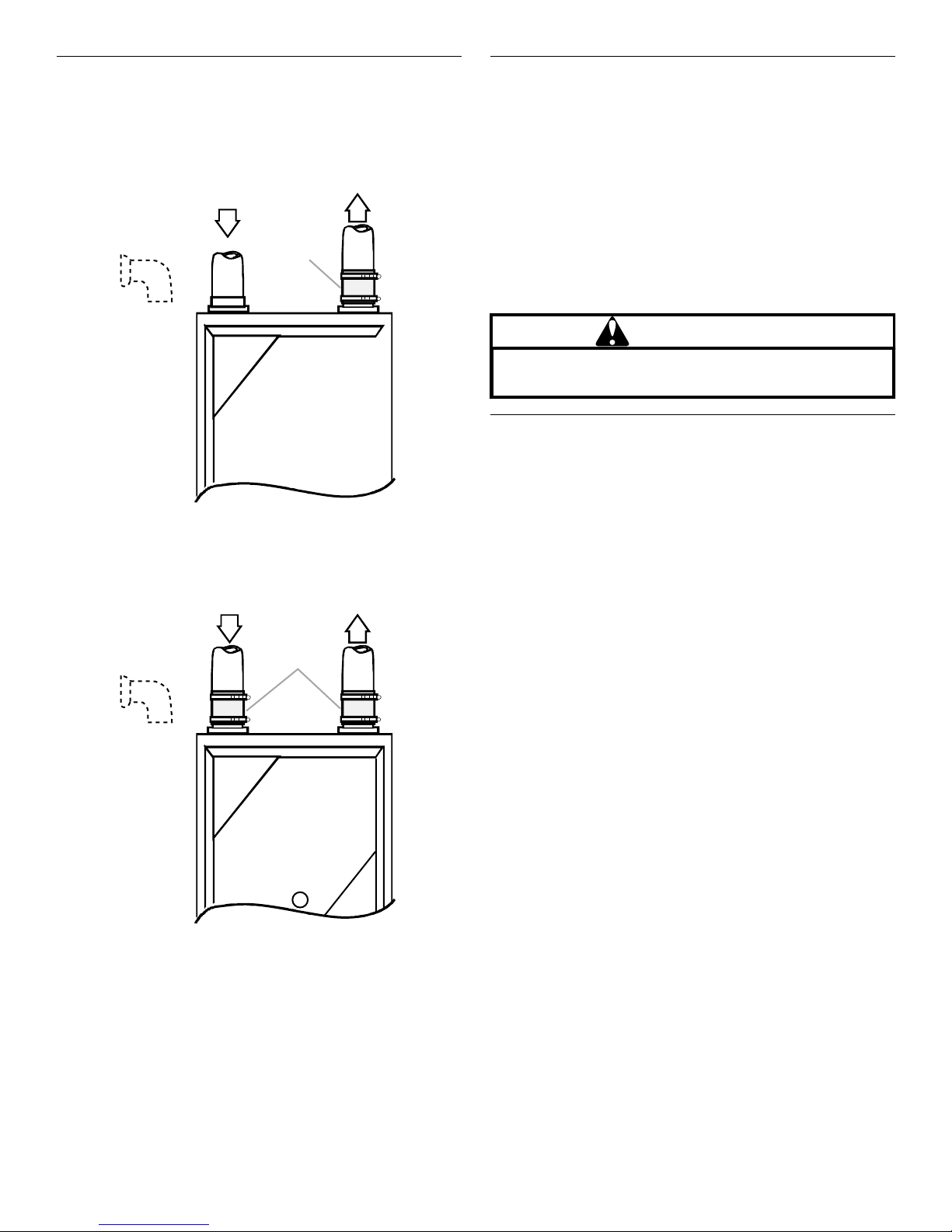
Increased Clearance Configuration
A
Clear Config G 2009
B
A. Vent pipe
B. 45º long-sweep elbows
NOTES:
■ Do not use other commercially available “no hub connectors”
due to possible material conflicts.
■ The vent/flue pipe can also be secured using a PVC or ABS
elbow or coupling using the appropriate glue (see “Materials
and Joining Methods”).
■ For nondirect vent installations, a minimum of one 90° elbow
should be installed on the combustion air intake coupling to
guard against inadvertent blockage.
Combustion Air Pipe—Direct Vent Installations
On upflow units, secure the combustion air intake pipe directly to
the air intake coupling. On counterflow units secure the
combustion air intake pipe to the air intake coupling using the
rubber coupling and worm gear hose clamps provided with the
unit. The counterflow rubber coupling allows service removal of
air intake piping internal to the furnace blower compartment.
NOTE: Because of probable material conflicts, do not use other
commercially available “no hub connectors.” The combustion air
intake pipe can also be secured directly to the counterflow unit
air intake pipe coupling.
15
Combustion Air Pipe—Nondirect Vent Installations
A minimum of one 90° elbow should be installed on the
combustion air intake coupling to guard against inadvertent
blockage.
Standard Connection—Upflow
B
A
A. 90º PVC elbow (nondirect vent only)
B. Combustion air pipe (direct
vent only)
C. Rubber coupling with worm
gear hose clamps
D. Vent/flue pipe
Standard Connection—Counterflow
B
C
A
A. 90º PVC elbow (nondirect
vent only)
B. Combustion air pipe (direct
vent only)
C. Rubber couplings with worm
gear hose clamps
D. Vent/flue pipe
C
D
D
Alternate Furnace Connections
If the standard locations are undesirable for a specific installation,
alternate side panel locations are available for both combustion
air inlet and vent/flue pipe connections. These locations may be
of particular benefit to upright upflow installations requiring
additional access to an A coil, or to upright counterflow
installations requiring additional access to a filter or electronic air
cleaner, or to horizontal installations desiring vent/flue (and
combustion air intake) piping run vertically from the side of the
cabinet.
NOTE: Standard and alternate locations can be combined (for
example, an installation may use the standard combustion air
intake location but use the alternate vent/flue location or vice
versa), if needed.
WARNING
Edges of sheet metal holes may be sharp. Use gloves as
a precaution when removing hole plugs.
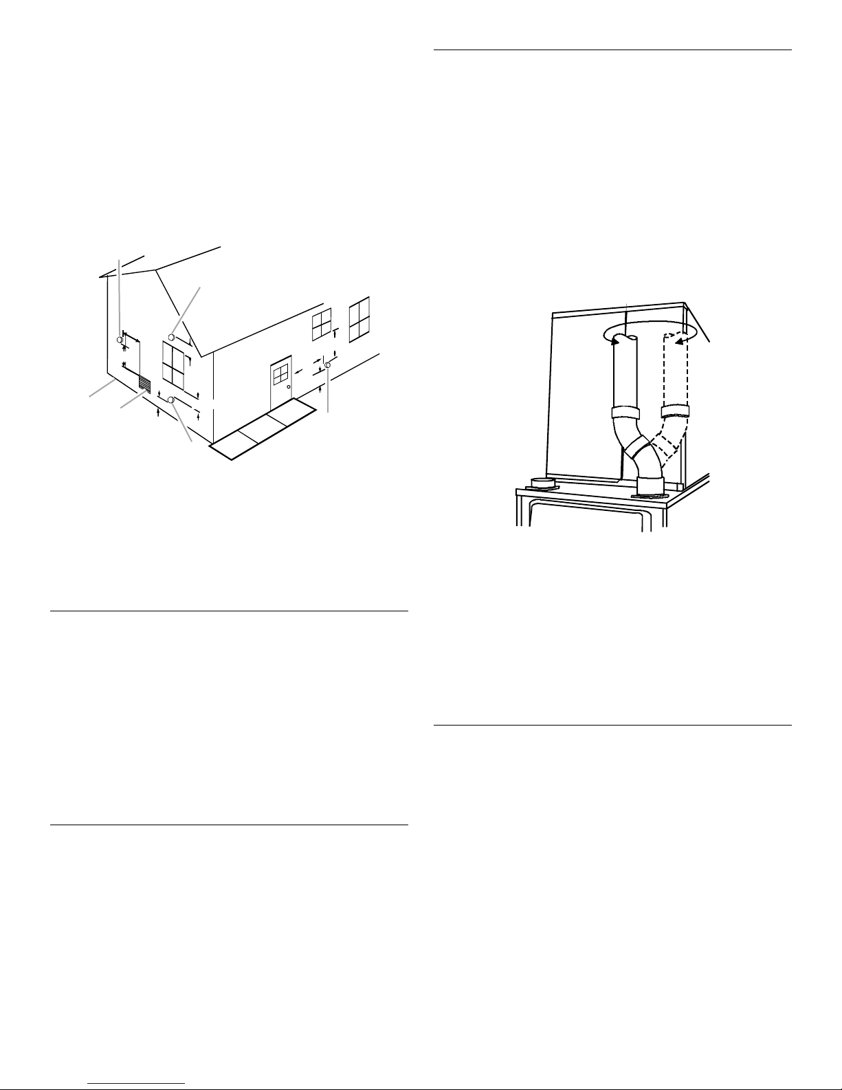
Alternate Vent/Flue Location
The alternate vent/flue location is the large hole directly in line
with the induced draft blower outlet. To use the alternate vent/flue
location, refer to the following steps and the “Alternate Vent/Flue
Location” illustration.
NOTE: Counterflow instructions follow the upflow instructions.
Upflow Units
1. Remove and save the 4 screws securing the vent/flue
coupling to the furnace top panel.
Counterflow Units
Remove and save the 4 screws securing the vent/flue
coupling to the furnace base pan. Also remove the 3 screws
securing the furnace’s internal vent/flue piping to the blower
deck.
Upflow and Counterflow Units
2. Loosen the worm gear hose clamps on the rubber elbow and
detach the rubber elbow from both the induced draft blower
and the vent/flue pipe.
3. Remove the vent/flue pipe from the furnace.
Upflow Units
4. Cut the vent/flue pipe 3³⁄₄" (9.5 cm) from the flanged end of
the pipe. See “Vent/Flue Pipe Cuts” illustration.
NOTE: The section of pipe attached to the coupling will reach
through the side panel to the induced draft blower.
5. Discard remaining pipe and elbows.
Counterflow Units
Cut the vent/flue pipe 3³⁄₄" (9.5 cm) from the blower deck
coupling. See “Vent/Flue Pipe Cuts” illustration
Save vent/flue pipe attached to the blower deck coupling for
use in the alternate location.
Discard remaining pipe and elbows.
Goodman 56
16
 Loading...