

Whirlpool WGFD295, WGFM295 Installation Instructions Manual
80% 2-STAGE VARIABLE SPEED GAS FURNACE
INSTALLATION INSTRUCTIONS
ATTENTION INSTALLATION PERSONNEL
As a professional installer, you have an obligation to know the product better than the customer. This includes all
safety precautions and related items. Prior to actual installation, thoroughly familiarize yourself with this instruction
manual. Pay special attention to all safety warnings. Often during installation or repair, it is possible to place
yourself in a position which is more hazardous than when the unit is in operations.
Remember, it is your responsibility to install the product safely and to know it well enough to be able to instruct a
customer in its safe use. Safety is a matter of common sense...a matter of thinking before acting. Most dealers have
a list of specific good safety practices...follow them.
The precautions listed in this installation manual are intended as supplemental to existing practices. However, if
there is a direct conflict between existing practices and the content of this manual, the precautions listed here take
precedence.
Placeholder
for Bar
Code
Keep this literature in a safe place for future reference.
Whirlpool Gold® Models
WGFD295, WGFM295
WPIO-369B
These furnaces comply with requirements embodied in the
American National Standard/National Standard of Canada ANSI
Z21.47-CSA-2.3 Gas Fired Central Furnaces.
Tradewinds Distributing Company, LLC
14610 Breakers Drive
Jacksonville, Florida 32258

TABLE OF CONTENTS
GAS FURNACE SAFETY PRECAUTIONS....................................3
Additional Safety Considerations.................................................4
PRODUCT DESCRIPTION AND APPLICATION ..........................4
Shipping Inspection .....................................................................4
Electrostatic Discharge (ESD) Precautions..................................4
To the Installer.............................................................................. 4
Important Note to the Owner Regarding Product Warranty .......5
Product Application......................................................................5
LOCATION REQUIREMENTS AND CONSIDERATIONS ............6
Clearances and Accessibility.......................................................7
Furnace Suspension ....................................................................7
Existing Furnace Removal ...........................................................8
Thermostat Location ....................................................................8
COMBUSTION AND VENTILATION AIR REQUIREMENTS........8
Category I Venting—Vertical Venting...........................................8
Category I Furnaces Only—Exterior Masonry Chimneys............9
ELECTRICAL CONNECTIONS....................................................13
Wiring Harness...........................................................................13
115-Volt Line Connections.........................................................13
Junction Box Relocation............................................................14
24-Volt Thermostat Wiring .........................................................14
24-Volt Dehumidistat Wiring ......................................................16
Fossil Fuel Applications .............................................................16
115-Volt Line Connection of Accessories (Humidifier and
Electronic Air Cleaner)................................................................16
GAS SUPPLY AND PIPING..........................................................17
High Altitude Derate...................................................................17
Propane Gas Conversion...........................................................17
Gas Piping Connections ............................................................18
Gas Piping Checks.....................................................................19
Propane Gas Tanks and Piping .................................................19
CIRCULATING AIR AND FILTERS..............................................21
Ductwork—Airflow .....................................................................21
Filters—Read this Section Before Installing the Return Air
Ductwork ....................................................................................21
START-UP PROCEDURE AND ADJUSTMENT.........................22
Heat Anticipator Setting.............................................................22
Furnace Operation .....................................................................22
Furnace Start-Up .......................................................................22
Furnace Shutdown.....................................................................22
Gas Supply Pressure Measurement..........................................22
Gas Manifold Pressure Measurement and Adjustment.............23
Gas Input Rate Measurement—Natural Gas Only.....................24
Temperature Rise.......................................................................24
Circulator Blower Speeds ..........................................................25
Blower Heat Off Delay Timings ..................................................27
NORMAL SEQUENCE OF OPERATION.....................................27
Power Up....................................................................................27
Heating Mode.............................................................................27
Cooling Mode.............................................................................28
Fan Only Mode...........................................................................28
Operational Checks....................................................................28
SAFETY CIRCUIT DESCRIPTION...............................................28
General .......................................................................................28
Integrated Control Module .........................................................28
Primary Limit Control..................................................................29
Auxiliary Limit Controls...............................................................29
Rollout Limit Controls.................................................................29
Pressure Switches......................................................................29
Flame Sensor..............................................................................29
MAINTENANCE ............................................................................29
Annual Inspection.......................................................................29
Filters ..........................................................................................29
Burners .......................................................................................30
Induced Draft and Circulator Blowers........................................30
Condensate Trap and Drain System (Qualified Servicer Only)..30
Flame Sensor (Qualified Servicer Only)......................................30
Flue Passages (Qualified Servicer Only) ....................................30
Before Leaving an Installation....................................................30
Repair and Replacement Parts..................................................30
TROUBLESHOOTING ..................................................................31
Electrostatic Discharge (ESD) Precautions................................31
Fault Recall.................................................................................31
Resetting from Lockout..............................................................31
Status Codes..............................................................................31
Diagnostic Chart.........................................................................32
DIP Switch Chart........................................................................38
WIRING DIAGRAM .......................................................................39
ASSISTANCE OR SERVICE.........................................................40
2
GAS FURNACE SAFETY PRECAUTIONS
Please adhere to the following warnings and cautions when installing, adjusting, altering, servicing or operating the furnace. To en sure
proper installation and operation, thoroughly read this manual for specifics pertaining to the installation and application of this product.
Recognize this symbol as a safety precaution.
WARNING
Hazards or unsafe practices could result in property
damage, product damage, severe personal injury or death.
Goodman 1
CAUTION
Hazards or unsafe practices may result in property
damage, product damage, personal injury or death.
WARNING
The manufacturer will not be responsible for any injury
or property damage arising from improper service or
service procedures. If you install or perform service on
this unit, you assume responsibility for any personal
injury or property damage which may result. Many
jurisdictions require a license to install or service
heating and air conditioning equipment.
Goodman 114
WARNING
To prevent personal injury or death due to improper
installation, adjustment, alteration,
refer to this manual. For additional assistance or
information, consult a qualified installer, service agency
or the gas supplier.
Goodman 44
service
or
maintenance,
WARNING
This product contains or produces a chemical or
chemicals which may cause serious illness or death and
which are known to the State of California to cause
cancer, birth defects or other reproductive harm.
Goodman 45
WARNING
Heating unit should not be utilized without reasonable,
routine inspection, maintenance and supervision. If the
building in which any such device is located will be
vacant, care should be taken that such device is
routinely inspected, maintained and monitored. In the
event that the building may be exposed to freezing
temperatures and will be vacant, all water-bearing pipes
should be drained, the building should be properly
winterized and the water source closed. In the event
that the building may be exposed to freezing
temperatures and will be vacant, any hydronic coil units
should be drained as well, and, in such case, alternative
heat sources should be utilized.
Goodman 47
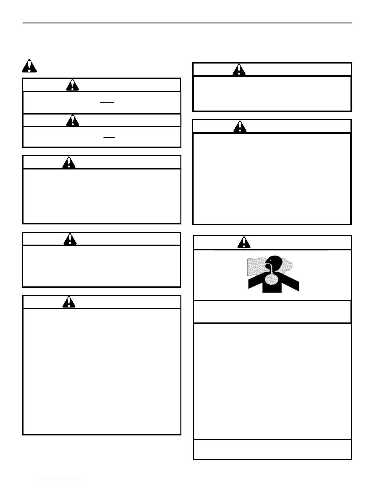
DANGER
WARNING
If the information in these instructions is not followed
exactly, a fire or explosion may result causing property
damage, personal injury or loss of life.
— Do not store or use gasoline or other flammable vapors
and liquids in the vicinity of this or any other appliance.
— WHAT TO DO IF YOU SMELL GAS
• Do not try to light any appliance.
• Do not touch any electrical switch; do not use any phone
in your building.
• Immediately call your gas supplier from a neighbor’s
phone. Follow the gas supplier’s instructions.
• If you cannot reach your gas supplier, call the fire
department.
— Installation and service must be performed by a
qualified installer, service agency or the gas supplier.
Goodman 42
CARBON MONOXIDE POISONING HAZARD
Special Warning for Installation of Furnace or Air Handling
Units in Enclosed Areas such as Garages, Utility Rooms or
Parking Areas.
Carbon monoxide producing devices (such as an
automobile, space heater, gas water heater, etc.) should
not be operated in enclosed areas such as unventilated
garages, utility rooms or parking areas because of the
danger of carbon monoxide (CO) poisoning resulting from
the exhaust emissions. If a furnace or air handler is
installed in an enclosed area such as a garage, utility room
or parking area and a carbon monoxide producing device is
operated therein, there must be adequate, direct outside
ventilation.
This ventilation is necessary to avoid the danger of CO
poisoning which can occur if a carbon monoxide producing
device continues to operate in the enclosed area. Carbon
monoxide emissions can be (re)circulated throughout the
structure if the furnace or air handler is operating in any
mode.
CO can cause serious illness including permanent brain
damage or death.
Goodman 38
3
WARNING
To prevent possible property damage, personal injury or
death due to electrical shock, the furnace must be located
to protect the electrical components from water.
Goodman 46
WARNING
Should overheating occur or the gas supply fail to shut
off, turn off the manual gas shutoff valve external to the
furnace before turning off the electrical supply.
Goodman 43
WARNING
Possible property damage, personal injury or death due
to fire, explosion, smoke, soot, condensation, electrical
shock or carbon monoxide may result from improper
installation, repair, operation or maintenance of this
product.
Goodman 48
WARNING
This unit must not be used as a “construction heater”
during the finishing phases of construction on a new
structure. This type of use may result in premature failure
of the unit due to extremely low return air temperatures
and exposure to corrosive or very dirty atmospheres.
Goodman 79
WARNING
To prevent possible personal injury or death due to
asphyxiation, this furnace must be Category I vented.
Do not vent using Category III venting.
Provisions must be made for venting combustion
products outdoors through a proper venting system.
The length of flue pipe could be a limiting factor in
locating the furnace.
Additional Safety Considerations
■ This furnace is approved for Category I venting only.
■ Provisions must be made for venting combustion products
outdoors through a proper venting system. The length of flue
pipe could be a limiting factor in locating the furnace.
Goodman 66
The furnace must be carefully inspected on arrival for damage
and bolts or screws which may have come loose in transit. In the
event of damage, the consignee should:
1. Make a notation on the delivery receipt of any visible damage
to the shipment or container.
2. Notify the carrier promptly and request an inspection.
3. With concealed damage, the carrier must be notified as soon
as possible—preferably within 5 days.
4. File the claim with the following support documents within a
9-month statute of limitations.
■ Original or certified copy of the Bill of Lading, or
indemnity bond.
■ Original paid freight bill or indemnity in lieu thereof.
■ Original or certified copy of the invoice, showing trade
and other discounts or reductions.
■ Copy of the inspection report issued by carrier’s
representative at the time damage is reported to carrier.
The carrier is responsible for making prompt inspection of the
damage and for a thorough investigation of each claim. The
distributor or manufacturer will not accept claims from dealers for
transportation damage.
Electrostatic Discharge (ESD) Precautions
NOTE: Discharge static electricity accumulated in the body
before touching the unit. An electrostatic discharge can adversely
affect electrical components.
Use the following steps during furnace installations and servicing
to protect the integrated control module from damage. By putting
the furnace, the control and the person at the same electrostatic
potential, these steps will help avoid exposing the integrated
control module to electrostatic discharge. This procedure is
applicable to both installed and uninstalled (ungrounded)
furnaces.
1. Disconnect all power to the furnace.
NOTE: Do not touch the integrated control module or any
wire connected to the control prior to discharging your body’s
electrostatic charge to ground.
2. Firmly touch a clean, unpainted, metal surface of the furnace
away from the control. Any tools held in a person’s hand
during grounding will be discharged also.
3. Service the integrated control module or connecting wiring
after following the discharge process in Step 2.
NOTE: Do not recharge your body with static electricity by
moving or shuffling your feet or touching ungrounded
objects. If you touch an ungrounded object, repeat Step 2
before touching the control or wires.
4. Follow steps 1 through 3 before removing a new control from
its container or installing the control on a furnace. Return any
old or new controls to their containers before touching any
ungrounded object.
PRODUCT DESCRIPTION AND
APPLICATION
Shipping Inspection
All units are securely packed in shipping containers tested
according to International Safe Transit Association specifications.
The carton must be checked upon arrival for external damage. If
damage is found, a request for inspection by carrier’s agent must
be made in writing immediately.
4
To the Installer
Before installing this unit, please read this manual thoroughly to
familiarize yourself with specific items which must be adhered to,
including, but not limited to:
■ Unit maximum external static pressure
■ Gas pressures
■ Btu input rating
■ Proper electrical connections
■ Circulating air temperature rise
■ Minimum or maximum CFM
■ Motor speed connections
NOTE: These furnaces are designed for Category I venting only.
Important Note to the Owner Regarding
Product Warranty
Your warranty certificate is supplied as a separate document with
the unit installed by your contractor. Read the limited warranty
certificate carefully to determine what is and is not covered. Keep
the warranty certificate in a safe place. If you are unable to locate
the warranty certificate, please contact your installing contractor,
or contact customer service at 1-866-944-7575 to obtain a copy.
To receive the Lifetime Heat Exchanger Limited Warranty, good
for as long as you own your home, and the 10-Year Parts Limited
Warranty, online registration must be completed within 60 days of
installation. Online registration is not required in California or
Quebec.
Product limited warranty certificates for models currently in
production can be viewed at www.whirlpoolhvac.com. If your
model is not currently in production or does not appear on the
website, please contact your installing contractor or contact
customer service at 1-866-944-7575 to obtain a copy of your
warranty certificate.
To register your unit, go to www.whirlpoolhvac.com. Click on the
manufacturer’s Comfort Commitment
TM
Warranty link located at
the bottom center of the home page. Next, click on the Click
Here to Register Your Product link located at the top center of the
page, and complete the forms in the manner indicated.
WARNING
To prevent property damage, personal injury or death due
to fire, do not install the furnace in a mobile home, trailer
or recreational vehicle.
Goodman 49
■ The vent system is permanently installed according to these
installation instructions.
■ A room thermostat is used to control the furnace. Fixed
jumpers that provide continuous heating cannot be used.
■ Return air ducts are provided and sealed to the furnace.
■ A return air temperature range between 60ºF and 80ºF (16ºC
and 27ºC) is maintained.
■ Air filters are installed in the system and maintained during
construction, replaced as appropriate during construction
and upon completion of construction.
■ The input rate and temperature rise are set according to the
furnace rating plate.
■ 100% outside air is provided for combustion air requirements
during construction. Temporary ducting can be used.
NOTE: Do not connect the temporary duct directly to the
furnace. The duct must be sized according to the instructions
in the “Combustion and Ventilation Air Requirements”
section.
■ The furnace heat exchanger, components, duct system, air
filters and evaporator coils are thoroughly cleaned following
the final construction cleanup.
■ All furnace operating conditions (including ignition, input rate,
temperature rise and venting) are verified according to these
installation instructions.
NOTE: The Commonwealth of Massachusetts requires that the
following additional requirements must also be met:
■ Gas furnaces must be installed by a licensed plumber or gas
fitter.
■ A T-handle gas cock must be used.
■ If the unit is to be installed in an attic, the passageway to and
the service area around the unit must have flooring.
Product Application
This furnace is primarily designed for residential home-heating
applications.
IMPORTANT:
■ This furnace is not designed or certified for use in mobile
homes, trailers or recreational vehicles.
■ This furnace is not designed or certified for outdoor
applications.
■ The furnace must be installed indoors (for example, attic
space, crawl space or garage area provided the garage area
is enclosed with an operating door).
This furnace can be used in the following nonindustrial
commercial applications:
■ Schools
■ Office buildings
■ Churches
■ Retail stores
NOTE: In such applications, the furnace must be installed with
the following stipulations:
■ It must be installed according to the installation instructions
provided and according to local and national codes.
■ It must be installed indoors in a building constructed on site.
■ It must be part of a ducted system and not used in a free air
delivery application.
■ It must not be used as a “makeup” air unit.
■ All other warranty exclusions and restrictions apply.
This furnace may be used as a construction site heater only if all
of the following conditions are met:
■ Nursing homes
■ Hotels/motels
■ Common areas
■ Office areas
WARNING
Goodman 49
To prevent property damage, personal injury or death due
to fire, do not install the furnace in a mobile home, trailer
or recreational vehicle.
To ensure proper furnace operation, you must install, operate and
maintain the furnace in accordance with these installation and
operation instructions, all local building codes and ordinances. In
their absence, follow the latest edition of the National Fuel Gas
Code (NFPA 54/ANSI Z223.1), and/or CAN/CSA B149 Installation
Codes, local plumbing or waste water codes and other
applicable codes.
A copy of the National Fuel Gas Code (NFPA 54/ANSI Z223.1)
can be obtained from any of the following:
American National Standards Institute
1430 Broadway
New York, NY 10018
National Fire Protection Association
1 Batterymarch Park
Quincy, MA 02269
CSA International
8501 East Pleasant Valley
Cleveland, OH 44131
A copy of the CAN/CSA B149 Installation Codes can also be
obtained from:
CSA International
178 Rexdale Boulevard
Etobicoke, Ontario, Canada M9W 1R3
5
The rated heating capacity of the furnace should be greater than
or equal to the total heat loss of the area to be heated. The total
heat loss should be calculated by an approved method or in
accordance with “ASHRAE Guide” or “Manual J-Load
Calculations” published by the Air Conditioning Contractors of
America.
In the U.S.A., this furnace must be installed in accordance with
the latest edition of the ANSI Z223.1 booklet titled “National Fuel
Gas Code” (NFPA 54), and the requirements or codes of the local
utility or other authority having jurisdiction. In Canada, this
furnace must be installed in accordance with the current CAN/
CGA-B149.1 and 2 Gas Installation Codes, local plumbing or
waste water codes and other applicable codes. Additional helpful
publications available from the NFPA are, NFPA 90A—Installation
of Air Conditioning and Ventilating System and NFPA 90B—Warm
Air Heating and Air Conditioning System.
LOCATION REQUIREMENTS AND CONSIDERATIONS
Your unit model type determines which installation procedures
must be used. For WGFM28 models, you must follow instructions
for horizontal left, horizontal right or upflow installations only.
These furnaces are not approved for downflow installations.
Downflow models WGFD28 are not approved for horizontal or
upflow installations. For these models, use only the instructions
for downflow installation only.
WARNING
To prevent possible equipment damage, property damage,
personal injury or death, the following bullet points must
be observed when installing the unit.
Follow the instructions listed below when selecting a furnace
location. Refer also to the guidelines provided in “Combustion
and Ventilation Air Requirements.”
■ Centrally locate the furnace with respect to the proposed or
existing air distribution system.
■ Check that the temperature of the return air entering the
furnace is between 55°F and 100°F (13ºC and 38ºC) when the
furnace is heating.
■ Provide provisions for venting combustion products outdoors
through a proper venting system.
NOTE: The length of flue piping can be a limiting factor in the
location of the furnace.
■ Ensure that adequate combustion air is available for the
furnace. Improper or insufficient combustion air can expose
the building occupants to gas combustion products that
could include carbon monoxide. Refer to “Combustion and
Ventilation Air Requirements.”
■ Set the furnace on a level floor. If the floor becomes wet or
damp at times, place the furnace above the floor on a
concrete base sized approximately 1¹⁄₂" (3.8 cm) larger than
the base of the furnace.
■ Ensure that the upflow or horizontal furnaces are not installed
directly on carpeting, or any other combustible material.
NOTE: The only combustible material allowed is wood.
Goodman 50
All venting shall be in accordance with PART 7, Venting of
Equipment, of the National Fuel Gas Code, ANSI Z223.1, or
applicable local building and/or air conditioning codes. These
publications are available from:
National Fire Protection Association, Inc.
1 Batterymarch Park
Quincy, MA 02269
NOTE: Furnaces with NOx screens meet the California NOx
emission standards and California seasonal efficiency standards.
Annual inspections of the furnace and its vent system is strongly
recommended.
■ Exposure to contaminated combustion air will result in safety
and performance-related problems.
NOTE: Do not install the furnace where the combustion air is
exposed to the following substances:
Chlorinated waxes or cleaners
Chlorine-based swimming pool chemicals
Water softening chemicals
Deicing salts or chemicals
Carbon tetrachloride
Halogen-type refrigerants
Cleaning solutions (such as perchloroethylene)
Printing inks
Paint removers
Varnishes
Hydrochloric acid
Cements and glues
Antistatic fabric softeners for clothes dryers
Masonry acid washing materials
■ If the furnace is used in connection with a cooling coil unit,
install the furnace upstream or in parallel with the cooling coil
unit. Premature heat exchanger failure will result if the cooling
coil unit is placed ahead of the furnace.
■ If the furnace is installed in an application where the typical
operating sound level of a furnace is deemed objectionable,
an optional sound reduction kit is available. Consult your
local distributor for more details.
■ If the furnace is installed in a residential garage, position the
furnace so that the burners and ignition source are located
not less than 18" (45.7 cm) above the floor. Protect the
furnace from physical damage by vehicles.
■ If the furnace is installed horizontally, ensure that the furnace
access doors are not on the “up/top” or “down/bottom” side
of the furnace. The furnace access doors must be vertical so
that the burners fire horizontally into the heat exchanger.
■ Do not connect the furnace to a chimney flue that serves a
separate appliance designed to burn solid fuel.
■ On counterflow installations, the air conditioning coil must be
downstream from the furnace heat exchanger.
6
Counterflow Installation Over a Noncombustible Floor
D
■ Before setting the furnace over the plenum opening, ensure
that the surface around the opening is smooth and level. A
tight seal should be made between the furnace base and
floor by using a silicone rubber caulking compound or
cement grout.
Counterflow Installation Over a Combustible Floor
■ If installation over a combustible floor becomes necessary,
use an accessory subbase (see Specification Sheet
applicable for your model for details). A special accessory
subbase must be used for upright counterflow unit
installations over any combustible material, including wood.
Refer to subbase instructions for installation details. Follow
the instructions with the subbase for proper installation.
NOTES:
■ Do not install the furnace directly on carpeting, tile or
other combustible material other than wood flooring.
■ The subbase will not be required if an air conditioning coil
is installed between the supply air opening on the furnace
and the floor.
Clearances and Accessibility
Unobstructed front clearance of 24" (61 cm) for servicing is
recommended.
Clearances to Combustibles—in. (cm)
Vent Pipe
B1-Vent Single Wall
Connector Sides Front Back Top (Plenum)
1 (2.5) 6 (15.2) 1 (2.4) 3 (7.6) 0 1 (2.5)
NOTE: Top clearance for horizontal configuration is 1" (2.5 cm).
B
A
■ Adequate combustion/ventilation air must be supplied to the
closet or enclosure.
■ Furnace must be completely sealed to the floor or base.
Combustion/ventilation air supply pipes must terminate 12"
(30.5 cm) from the top of the closet or enclosure and 12"
(30.5 cm) from the floor of the closet or enclosure.
NOTE: Do not remove the solid base plate for the side return.
■ Return air ducts must be completely sealed to the furnace
and terminate outside the enclosure surfaces.
Horizontal Installation—WGFM28 Models Only
Line contact to framing is permitted when installed in the
horizontal configuration. Line contact is defined as the portion of
the cabinet that is formed by the intersection of the top and side.
IMPORTANT: Accessibility clearance, where greater, should take
precedence over minimum fire protection clearance.
■ A gas-fired furnace for installation in a residential garage
must be installed so that the ignition source and burners are
located not less than 18" (45.7 cm) above the floor and are
protected or located to prevent physical damage by vehicles.
■ A gas furnace must not be installed directly on carpeting, tile,
or other combustible materials other than wood flooring.
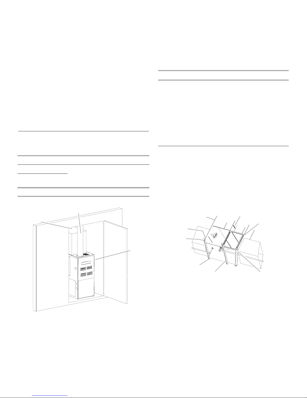
Furnace Suspension
If suspending the furnace from rafters or joists, use ³⁄₈" threaded
rod and 2" x 2" x ¹⁄₈" (5.1 cm x 5.1 cm x 3.2 mm) angle iron as
shown in “Suspended Furnace” illustration. The length of rod will
depend on the application and the clearances necessary.
NOTE: In a horizontal installation, the air conditioning coil must
be adequately supported by the proper brackets and supports.
Inadequate coil support can result in furnace cabinet distortion
and air leakage.
Suspended Furnace
A
H
B
C
Clear Combust G 2009
A. Top clearance—1" (2.5 cm)
B. Vent pipe clearance—6" (15.2 cm)
for single wall connector, 1"
(2.5 cm) for B-1 vent
C
E
C. Back clearance—0"
D. Side clearance—1" (2.5 cm)
E. Front clearance—3" (7.6 cm)
G
F
A.
³⁄₈
" (1 cm) diameter threaded
rod (6)
B. 8" (20.3 cm) minimum clearance
between center rod and furnace
cabinet to allow for circulator
blower removal.
C. Level furnace end to end, slight
forward tilt with front 0" to
(1.9 cm) below back.
³⁄₄
"
DE
D. Tilt outward to allow for door
and circulator blower removal.
E. Position as close as possible to
blower deck to allow for
circulator blower removal.
F. 2" x 2" x
3.2 mm) angle iron (3)
G. Support nuts
H. Hold down nuts
¹⁄₈
" (5.1 cm x 5.1 cm x
7
Existing Furnace Removal
NOTE: When an existing furnace is removed from a venting
system serving other appliances, the venting system may be too
large to properly vent the remaining attached appliances.
The following vent testing procedure is reproduced from the
American National Standard/National Standard of Canada for
Gas-Fired Central Furnaces ANSI Z21.47—latest edition,
CSA-2.3 latest edition Section 1.23.1.
The following steps shall be followed with each appliance
connected to the venting system placed in operation, while any
other appliances connected to the venting system are not in
operation:
1. Seal any unused openings in the venting system.
2. Inspect the venting system for proper size and horizontal
pitch, as required by the National Fuel Gas Code, ANSI
Z223.1 or the Natural Gas and Propane Installation Code,
CSA B149.1-05 and these instructions. Determine that there
is no blockage or restriction, leakage, corrosion and other
deficiencies which could cause an unsafe condition.
3. As far as practical, close all building doors and windows and
all doors between the space in which the appliance(s)
connected to the venting system are located and other
spaces of the building.
4. Close fireplace dampers.
5. Turn on clothes dryers and any appliance not connected to
the venting system. Turn on any exhaust fans, such as range
hoods and bathroom exhausts, so they shall operate at
maximum speed. Do not operate a summer exhaust fan.
6. Follow the lighting instructions. Place the appliance being
inspected in operation. Adjust thermostat so appliance shall
operate continuously.
7. Test for spillage from draft hood appliances at the draft hood
relief opening after 5 minutes of main burner operation. Use
the flame of a match or candle.
8. After it has been determined that each appliance connected
to the venting system properly vents when tested as outlined
above, return doors, windows, exhaust fans, fireplace
dampers and any other gas-burning appliance to their
previous conditions of use.
9. If improper venting is observed during any of the above tests,
the venting system must be corrected in accordance with the
National Fuel Gas Code, ANSI Z223.1/NFPA 54 and/or
Natural Gas and Propane Installation Code, CSA B149.1-05.
If resizing is required on any portion of the venting system, use
the appropriate table in Appendix G in the latest edition of the
National Fuel Gas Code, ANSI Z223.1 and/or Natural Gas and
Propane Installation Code, CSA B149.1-05.
Thermostat Location
The thermostat should be placed approximately 5 ft (1.5 m) from
the floor on a vibration-free, inside wall in an area having good air
circulation.
NOTE: Do not install the thermostat where it may be influenced
by any of the following:
■ Drafts, or dead spots behind doors, in corners or under
cabinets
■ Hot or cold air from registers
■ Radiant heat from the sun
■ Light fixtures or other appliances
■ Radiant heat from a fireplace
■ Concealed hot or cold water pipes or chimneys
■ Unconditioned areas behind the thermostat, such as an
outside wall
Consult the instructions packaged with the thermostat for
mounting instructions and further precautions.
COMBUSTION AND VENTILATION AIR REQUIREMENTS
WARNING
To avoid property damage, personal injury or death,
sufficient fresh air for proper combustion and ventilation
of flue gases must be supplied. Most homes require
outside air be supplied into the furnace area.
Improved construction and additional insulation in buildings have
reduced heat loss by reducing air infiltration and escape around
doors and windows. These changes have helped in reducing
heating/cooling costs but have created a problem supplying
combustion and ventilation air for gas-fired and other
fuel-burning appliances. Appliances that pull air out of the house
(clothes dryers, exhaust fans, fireplaces, etc.) increase the
problem by starving appliances for air.
House depressurization can cause back drafting or improper
combustion of gas-fired appliances, thereby exposing building
occupants to gas combustion products that could include carbon
monoxide.
If this furnace is to be installed in the same space with other gas
appliances, such as a water heater, ensure that there is an
adequate supply of combustion and ventilation air for the other
appliances. Refer to the latest edition of the National Fuel Gas
Code NFPA 54/ANSI Z223.1 or Natural Gas and Propane
Installation Code, CSA B149.1-05 or applicable provisions of the
local building codes for determining the combustion air
requirements for the appliances.
Goodman 51
NOTE: This furnace must use indoor air for combusion. It cannot
be installed as a direct vent, or sealed combustion, furnace.
Most homes will require outside air to be supplied to the furnace
area by means of ventilation grilles or ducts connecting directly
to the outdoors or spaces open to the outdoors such as attics or
crawl spaces.
Category I Venting—Vertical Venting
WARNING
Goodman 66
To prevent possible personal injury or death due to
asphyxiation, this furnace must be Category I vented.
Do not vent using Category III venting.
Provisions must be made for venting combustion
products outdoors through a proper venting system.
The length of flue pipe could be a limiting factor in
locating the furnace.
Category I Venting is venting at a nonpositive pressure. A furnace
vented as Category I is considered a fan-assisted appliance. The
vent system does not have to be “gas tight.”
NOTE: Single-stage gas furnaces with induced draft blowers
draw products of combustion through a heat exchanger allowing,
in some instances, common venting with natural draft appliances
(for example, water heaters).
8
All installations must be vented in accordance with National Fuel
Gas Code NFPA 54/ANSI Z223.1—latest edition. In Canada, the
furnaces must be vented in accordance with the National
Standard of Canada, CAN/CSA B149.1 and CAN/CSA B149.2—
latest editions and amendments.
NOTE: The vertical height of the Category I venting system must
be at least as great as the horizontal length of the venting system.
WARNING
To prevent possible personal injury or death, due to
asphyxiation, common venting with other manufacturer's
induced draft appliances is not allowed.
The minimum vent diameter for the Category I venting system is
as shown in the Minimum Vent chart.
Minimum Vent
Model Upflow Counterflow
70 4" (10.2 cm) 4" (10.2 cm)
90 4" (10.2 cm) 4" (10.2 cm)
115 5" (12.7 cm) 4" (10.2 cm)
Under some conditions, larger vents than those shown in the
Minimum Vent chart may be required or allowed. When an
existing furnace is removed from a venting system serving other
appliances, the venting system may be too large to properly vent
the remaining attached appliances.
Upflow or horizontal units are shipped with the induced draft
blower discharging from the top of the furnace. (“Top” is as
viewed for an upflow installation.) The induced draft blower can
be rotated 90 degrees with the Chimney Transition Bottom kit
(0270F01119) for Category I venting. For horizontal installations,
a 4" (10.2 cm) single-wall pipe can be used to extend the induced
draft blower outlet ¹⁄₂" (1.3 cm) beyond the furnace cabinet.
NOTE: This product is not designed for counterclockwise
induced draft blower rotation.
Vent the furnace in accordance with the National Fuel Gas Code
NFPA 54/ANSI Z223.1—latest edition. In Canada, vent the
furnace in accordance with the National Standard of Canada,
CAN/CSA B149.1 and CAN/CSA B149.2—latest editions and
amendments.
Venting—Furnace Installed in Horizontal Position
NOTE: This furnace is not design certified to be horizontally
vented through an exterior side wall.
The following describes an optional venting procedure when the
furance is installed in the horizontal left discharge position.
To rotate the induced draft blower clockwise, you will need to
purchase one chimney transition bottom kit (Part Number
0270F01119).
1. Disconnect electrical power from the furnace.
2. Disconnect the induced draft blower power leads, flue pipe
and pressure switch tubing.
3. Remove the round cutout from the right side of the wrapper.
4. Remove and save the 4 screws that fasten the induced draft
blower to the flue collector box.
5. Remove and save the 3 screws that hold the chimney
assembly to the induced draft blower.
Goodman 67
6. Remove and save the 4 screws that fasten the chimney top to
the chimney bottom.
7. Remove the chimney transition bottom from the transition
bottom kit.
8. Install the chimney top with the 4 screws retained from Step
6 onto the new chimney transition bottom from the transition
bottom kit.
9. Remove the induced draft blower and install the new chimney
assembly to it using the 3 screws retained in Step 5.
10. Rotate the induced draft blower 90 degrees to the right,
feeding the flue pipe through the round cutout from the
outside of the wrapper, and fitting the blower onto the
chimney top assembly.
11. Secure the pipe to the chimney top from the front, top and
bottom using 3 screws. Rotate the induced draft blower to
properly orient the assembly.
NOTE: If the pipe section is less than 18" (45.7 cm), then
attach it directly to the chimney top on 3 sides, and feed it
through the round cutout from the inside of the wrapper.
12. Reattach the induced draft blower using the 4 screws
retained in Step 4. Ensure that the gasket located between
the induced draft blower and collector box is rotated
accordingly.
13. Reconnect the induced draft blower power leads.
NOTE: If the wires are not long enough, pull extra wire from
the wire bundle in the blower compartment.
14. Reconnect the remaining flue pipe and the pressure switch
tubing. Ensure that all wires and the pressure switch tubing
are at least 1" (2.5 cm) from the flue pipe, or any other hot
surface.
15. Reconnect electrical power to the furnace.
NOTE: In a horizontal installation, the air conditioning coil must
be adequately supported by the proper brackets and supports.
Inadequate coil support can result in furnace cabinet distortion
and air leakage.
Category I Furnaces Only—Exterior Masonry
Chimneys
An exterior masonry chimney is defined as a “Masonry chimney
exposed to the outdoors on one or more sides below the roof
line.” The ability to use a clay-lined masonry chimney depends on
a parameter not associated with interior chimneys. This variable
is the geographic location of the installation. Researchers have
discovered that the winter design temperatures have a direct
impact on the suitability of this type of venting. In most situations,
the existing masonry chimneys will require a properly-sized
metallic liner.
Counterflow units are shipped with the induced draft blower
discharging from the top (as viewed for a counterflow installation)
of the furnace.
Vent the furnace in accordance with the National Fuel Gas Code
NFPA 54/ANSI Z223.1—latest edition. In Canada, vent the
furnace in accordance with the National Standard of Canada,
CAN/CSA B149.1 AND CAN/CSA B149.2—latest editions and
amendments.
WARNING
Never allow the products of combustion, including carbon
monoxide, to enter the return ductwork or circulation air
supply.
Goodman 68
9
WARNING
C
D
E
F
G
H
I
J
K
Possiblility of property damage, personal injury or death.
Damaging condensation can occur inside masonry
chimneys when a single fan-assisted Category I appliance
(80% AFUE furnace) is vented without adequate dilution
air. Do not connect an 80% furnace to a masonry chimney
unless the furnace is common vented with a draft hood
equipped appliance or the chimney is lined with a metal
liner or Type B metal vent. All installations using masonry
chimneys must be sized in accordance with the
appropriate venting tables. If an 80% furnace is common
vented with a draft hood equipped appliance, the potential
for condensation damage may still exist with extremely
cold conditons, long vent connectors, exterior chimneys
or any combination of these conditions. The risk of
condensation damage is best avoided by using the
masonry chimney as a pathway for properly-sized metal
liner or Type B metal vent.
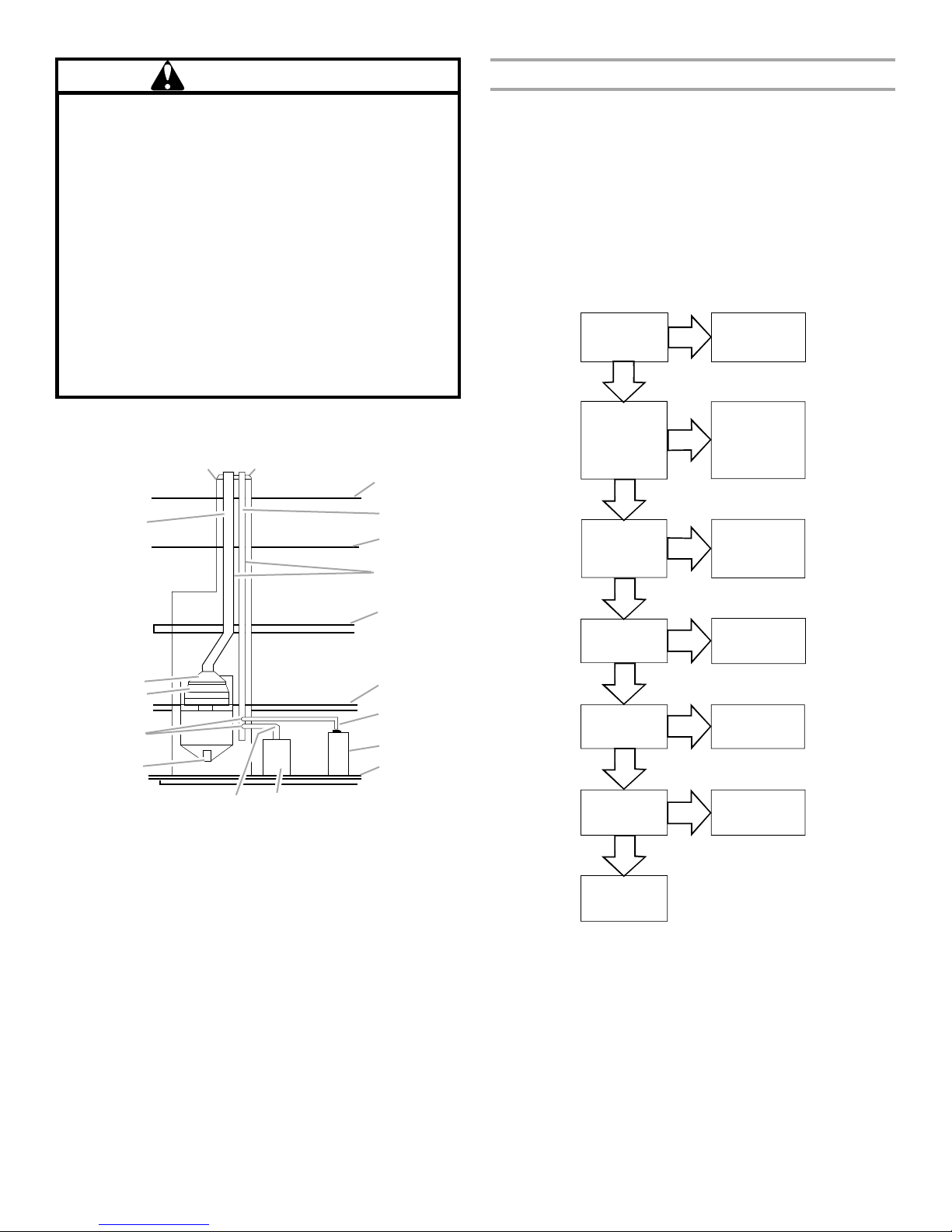
Typical Multiple Flue Clay Tile Chimney
Goodman 69
AB
Checklist Summary
This checklist serves as a summary of the items to be checked
before venting an 80+ furnace into a masonry chimney. In
addition, we recommend that a qualified serviceman use this
checklist to perform a yearly inspection of the furnace venting
system.
This checklist is only a summary. For detailed information on
each of the procedures mentioned, see the paragraph referenced
with each item.
This inspection is based upon a draft topical report, “Masonry
Chimney Inspection and Relining,” issued by the Gas Research
Institute. While not yet finalized, we believe this report represents
the best information on this subject which is currently available.
Proper chimney
termination?
(Check 1)
Yes
Chimney channel
free of solid and
liquid fuel
appliances?
(Check 2)
Yes
Line, terminate with
No
No
listed vent cap
(Fix 1)
Change venting
arrangements
(Fix 2)
R
Mult Flue Clay Chimney
Q
P
O
N
A. Crown
B. Wash
C. Roof line
D. Clay tile size: 8" x 8" x
12" (24.3 cm x 24.3 cm
x 30.5 cm) (each x 24"
[61 cm] length)
E. Attic floor
¹⁄₂
" to 1 " (1.3 cm to
F.
2.5 cm) air space
G 2009
L
M
G. Second floor
H. First floor
I. Water heater vent
connector
J. Natural draft water
heater
K. Basement floor
L. Fan-assisted
forced air furnace
M. Forced air furnace
vent connector
N. Clean out
O. Breech
P. D a m p e r
Q. Throat
R. Clay tile size:
generally 12" x 12"
(30.5 cm x 30.5 cm)
(24" [61 cm] length)
Crown in good
condition?
(Check 3)
Flowchart
G
Yes
No
Rebuild crown
(Fix 3)
and/or reline
(Fix 4)
2009
Cleanout free of
debris?
(Check 4)
Yes
Liner in good
condition?
(Check 5)
Yes
Dilution air
available?
(Check 6)
Yes
Complete the
installation.
(Check 7)
No
No
No
Reline
(Fix 4)
Reline
(Fix 4)
Reline
(Fix 4)
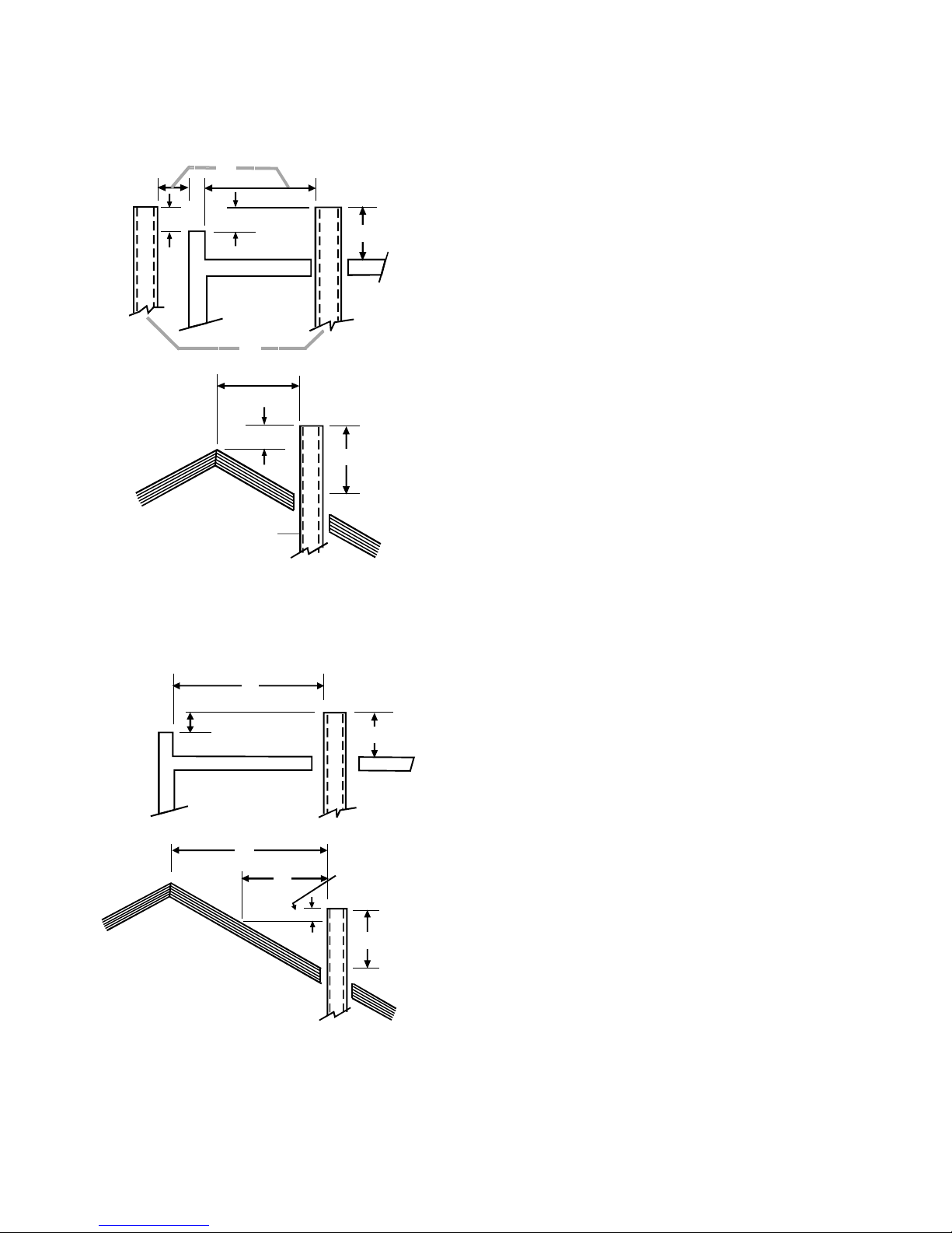
Check 1—Proper Chimney Termination
A masonry chimney used as a vent for gas-fired equipment must
extend at least 3 ft (91.4 cm) above the highest point where it
passes through the roof. It must extend at least 2 ft (61 cm)
higher than any portion of a building within a horizontal distance
of 10 ft (3 m). In addition, the chimney must terminate at least 3 ft
(91.4 cm) above any forced air inlet located within 10 ft (3 m). The
chimney must extend at least 5 ft (1.5 m) above the highest
connected equipment draft hood outlet or flue collar.
10
If the chimney does not meet these termination requirements, but
all other requirements in the checklist can be met, it may be
possible for a mason to extend the chimney. If this will not be
practical, see “Fix 1—Liner Termination.”
Termination 10 ft (3 m) or Less From Ridge, Wall or Parapet
A
Check 2—Any Solid or Liquid Fuel Appliances Vented into
This Chimney Channel
Solid fuel appliances include fireplaces, wood stoves, coal
furnaces and incinerators.
Liquid fuel appliances include oil furnaces, oil-fired boilers and
oil-fired water heaters.
Appliances which burn propane (sometimes referred to as LP
[liquefied petroleum]) gas are considered gas-fired appliances.
B
B
C
10 ft or Less G 2009
D
E
A
B
F
C
E
A. 10 ft (3 m) or less
B. 2 ft (61 cm) minimum
C. 3 ft (91.4 cm) minimum
D. Wall or parapet
E. Chimney(s)
Termination More Than 10 ft (3 m) From Ridge, Wall or
Parapet
A
B
E
10 ft or More G 2009
I
A. More than 10 ft (3 m)
B. No height above parapet
required when distance from
walls or parapet is more than
10 ft (3 m).
C. 3 ft (91.4 cm) minimum
D. Chimney
A
G
H
E. Wall or parapet
F. Height above any roof surface
within 10 ft (3 m) horizontally
G. 10 ft (3 m)
H. 2 ft (61 cm) minimum
I. Ridge
C
D
F
C
D
Check 3—Chimney Crown Condition
Damage from condensate normally appears first in the crown. If
any of the following trouble signs are present, the condition of the
crown is not satisfactory.
■ Crown leaning—“Fix 3—Rebuild the Crown”
■ Bricks missing—“Fix 3—Rebuild the Crown”
■ Mortar missing—“Fix 3—Rebuild the Crown”
■ Tile liner cracked—“Fix 4—Relining”
■ No tile liner—“Fix 4—Relining”
■ Salt staining at mortar joints (white stains and mortar
becomes sandy and/or erodes)—“Fix 4—Relining”
IMPORTANT: It may be necessary to follow both “Fix 3—Rebuild
the Crown” and “Fix 4—Relining.”
Check 4—Debris in Cleanout
A cleanout (dropleg) must be in a location where the upper edge
of the cleanout cover is at least 12" (30.5 cm) below the lower
edge of the lowest chimney inlet opening.
A chimney without a cleanout could become partially blocked by
debris. If no cleanout is present, the chimney must be relined (Fix
4—Relining). Remove the cleanout cover, and examine the
cleanout for debris. If significant amounts of any of the following
are found, reline the chimney (Fix 4—Relining).
■ Fuel oil residue
■ Bricks
■ Mortar or sand
■ Pieces of the tile liner
■ Rusted pieces of the metallic liner
Check 5—Liner Condition
If a metal liner is present, it must be checked. It cannot be
assumed that all existing metal liners are correctly installed and in
good condition.
Remove the lowest existing vent connector and examine the
inside of the elbow or tee at the base of the liner. A small amount
of soot may be considered acceptable, provided the installer
vacuums it away. If rusted pieces of the liner have collected here,
the metal liner must be removed and replaced (Fix 4—Relining).
Next, gently tap the inside of the liner with a Phillips screwdriver.
If the screwdriver perforates the liner, or if the tapping does not
sound like metal hitting metal, the liner must be removed and
replaced (Fix 4—Relining).
REMEMBER: All appliances must be vented inside the liner.
Venting one appliance inside the liner and another appliance
outside the liner is not acceptable.
Next, use a flashlight and a small mirror to look up inside the liner.
B-vent must be supported so as to not come into direct contact
with the chimney walls or tile liner. If it is not, it can probably be
rehung so as to be acceptable. A thimble or fire stop may be
helpful here.
11

Flexible liners should be hung straight or nearly straight. If it is
spiraled in the chimney and in good condition, it should be
rehung. To do this, break the top seal. Pull up and cut off the
excess liner length and refit the top seal. Use caution when doing
this, since the cut edges of flexible liners may be sharp.
The surfaces of the liner must be physically sound. If gaps or
holes are present, the metal liner must be removed and replaced
(Fix 4—Relining). Finally, confirm that the metal liner is the correct
size for the appliances to be installed. Use the GAMA tables and
rules.
NOTE: If a metal liner is not present, a clay tile liner must be
present, or the chimney must be lined (Fix 4—Relining).
Use a flashlight and small mirror at the cleanout or vent
connector to inspect the clay tile liner. If any of the following
problems are present, reline (Fix 4—Relining).
■ Tile sections misaligned
■ Tile sections missing
■ Gaps between tile sections
■ Signs of condensate drainage at the cleanout or vent
connectors
■ Mortar protruding from between tile sections
■ Use of sewer pipe or drainage pipe rather than an approved
fire clay tile
Next, measure the size of the liner. It may be possible to do this
from the cleanout. The liner must be at least as large as the
minimum size established by the tables in National Fuel Gas
Code NFPA 54/ANSI Z223.1—latest edition and in the National
Standard of Canada, CAN/CSA B149.1 and CAN/CSA B149.2—
latest editions and amendments. If the liner is too small or too
large, then the chimney must be relined (Fix 4—Relining).
Check 6—Dilution Air
If gas-fired appliances are to be vented into a clay tile liner, a
source of dilution air is required.
Dilution air cannot be obtained through the following:
■ Induced draft appliances
■ Natural draft appliances with vent dampers
Sufficient dilution air can ordinarily be obtained through the draft
hood of a natural draft appliance only if the appliance’s vent
connector does not include a vent damper. If dilution air will not
be available, the chimney must be relined (Fix 4—Relining).
Check 7—Complete the Installation
If checks 1 through 6 have been satisfactory, and the liner is an
acceptable size as determined by the tables in National Fuel Gas
Code NFPA 54/ANSI Z223.1—latest edition and in the National
Standard of Canada, CAN/CSA B149.1 and CAN/CSA B149.2—
latest editions and amendments, then the clay tile liner can
probably be used as a vent for the gas appliances. However, the
installer must keep in mind the following factors which may
render the tile liner unsuitable for use as a vent:
■ Extremely cold weather
■ Long vent connectors
■ Masonry chimneys with no air gap between the liner and the
bricks—difficult to detect
■ Exterior chimneys (the tables in National Fuel Gas Code
NFPA 54/ANSI Z223.1—latest edition and in the National
Standard of Canada, CAN/CSA B149.1 and CAN/CSA
B149.2—latest editions and amendments assume interior
chimneys)
If, in the judgment of the local gas utility, installer and/or local
codes, one or more of the above factors is likely to present a
problem, the chimney must be relined (Fix 4—Relining).
Fix 1—Liner Termination
Any cap or roof assembly used with a liner must be approved by
the liner manufacturer for such use. The liner and cap/roof
assembly must then terminate above the roof in accordance with
the manufacturer’s instructions.
In some cases, a shorter extension above the roof may be
possible with a liner than would be required with a masonry
chimney.
For further information on relining, see “Fix 4—Relining.”
Fix 2—Change Venting Arrangements
If the masonry chimney has more than one channel, it may be
possible to vent the gas appliances into one channel and vent the
solid or liquid fuel appliance(s) into another channel(s). Do not
vent an 80+ furnace inside of a metal liner with other appliances
vented outside the liner.
Alternatively, the homeowner may agree to discontinue use of the
fireplace (solid fuel appliance). If so, the tile liner must be cleaned
to remove creosote buildup. The fireplace opening must then be
permanently sealed.
If oil-fired appliance(s) are being replaced by gas-fired
appliance(s), the tile liner must first be cleaned to remove the fuel
oil residue.
If none of the above options is practical, the furnace may need to
be vented vertically with a B-vent.
Under some conditions, a 90%+ furnace could be installed rather
than an 80% furnace. The 90%+ furnace can be vented
horizontally or vertically through PVC pipe.
Fix 3—Rebuild the Crown
If the chimney crown is damaged, a qualified mason must repair
it in accordance with nationally recognized building codes or
standards. One such standard which may be referenced is the
Standard for Chimneys, Fireplaces, Vents, and Solid Fuel Burning
Appliances, ANSI/NFPA 211.
Fix 4—Relining
Relining options include B-vent and flexible liners.
If the chimney has diagonal offsets, B-vent probably cannot be
used.
If B-vent is to be used, it must be supported adequately.
Supports (such as fire stops or thimbles) must be used to keep
the B-vent from coming into direct contact with the tile liner or
chimney walls. Direct contact would result in higher heat loss,
with an increased possibility of poor venting system
performance.
It is not acceptable to vent one appliance inside the B-vent and
other appliances outside.
The excess space between the B-vent and the chimney walls
must be covered at the top of the chimney by a weatherproof,
corrosion resistant flashing. The B-vent should then be topped
with a listed vent cap. The listed vent cap will, when installed
according to the manufacturer’s instructions, prevent problems
due to rain, birds or wind effects.
A B-vent installed as described in this section is considered to be
an enclosed vent system, and the sizing tables in National Fuel
Gas Code NFPA 54/ANSI Z223.1—latest edition and in the
National Standard of Canada, CAN/CSA B149.1 and CAN/CSA
B149.2—latest editions and amendments may be used.
12
 Loading...