

Page 1
80% 2-STAGE VARIABLE SPEED GAS FURNACE
INSTALLATION INSTRUCTIONS
Table of Contents
GAS FURNACE SAFETY................................................................1
INSTALLATION REQUIREMENTS................................................3
Tools and Parts ............................................................................3
Location Requirements................................................................4
Installation Configurations ...........................................................5
Ductwork Requirements ..............................................................6
Electrical Requirements ...............................................................6
Gas Supply Requirements...........................................................6
Venting Requirements..................................................................6
INSTALLATION INSTRUCTIONS..................................................8
Inspect Shipment.........................................................................8
Plan Vent System.........................................................................8
Determine Vent Pipe Direction...................................................12
Connect Venting.........................................................................14
Install Ductwork..........................................................................15
Filter Specifications....................................................................15
Make Electrical Connections .....................................................16
GAS FURNACE SAFETY
Make Gas Connections..............................................................16
Check the Furnace Input Rate ...................................................17
Adjust the Furnace Input Rate ...................................................17
Complete Installation..................................................................18
Shut Down..................................................................................22
SEQUENCE OF OPERATION (VARIABLE SPEED MODELS)...23
Heating .......................................................................................23
Fan On........................................................................................23
Cooling .......................................................................................23
SEQUENCE OF OPERATION (MULTI-SPEED MODELS).........24
Heating .......................................................................................24
Fan On........................................................................................24
Cooling .......................................................................................24
CONTROLS ...................................................................................25
TROUBLESHOOTING ..................................................................26
ASSISTANCE OR SERVICE.........................................................31
Accessories ................................................................................31
Your safety and the safety of others are very important.
We have provided many important safety messages in this manual and on your appliance. Always read and obey all safety
messages.
This is the safety alert symbol.
This symbol alerts you to potential hazards that can kill or hurt you and others.
All safety messages will follow the safety alert symbol and either the word “DANGER” or “WARNING.”
These words mean:
You can be killed or seriously injured if you don't immediately
DANGER
WARNING
All safety messages will tell you what the potential hazard is, tell you how to reduce the chance of injury, and tell you what can
happen if the instructions are not followed.
Whirlpool Gold® Models
WGFBT, WGFBLT, WGFAT, WGFAR
47724B008
Whirlpool® Home Cooling and Heating
follow instructions.
can be killed or seriously injured if you don't
You
instructions.
14610 Breakers Drive
Jacksonville, FL 32258
follow
Page 2
IMPORTANT SAFETY INSTRUCTIONS
Use only with type of gas approved for this furnace.
■
Refer to the furnace rating plate.
Install this furnace only in a location and position
■
as specified in the “Location Requirements” section
of these instructions.
Provide adequate combustion and ventilation air to
■
the furnace space as specified in the “Venting
Requirements” section of these instructions.
■
Combustion products must be discharged outdoors.
Connect this furnace to an approved vent system
only, as specified in the “Venting Requirements”
section of these instructions.
Never test for gas leaks with an open flame. Use a
■
commercially available soap solution made
specifically for the detection of leaks to check all
connections, as specified in the “Make Gas
Connections” section of these instructions.
Adequate clearance must be provided around the
■
vent-air intake terminals.
Always install furnace to operate within the furnace’s
■
intended temperature-rise range with a duct system
which has an external static pressure within the
allowable range, as specified in the “Complete
Installation” section of these instructions. See
furnace rating plate.
■
When a furnace is installed so that supply ducts
carry air circulated by the furnace to areas outside
the space containing the furnace, the return air
shall also be handled by duct(s) sealed to the
furnace casing and terminating outside the space
containing the furnace.
A gas-fired furnace for installation in a residential
■
garage must be installed as specified in the
“Location Requirements” section of these
instructions.
■
The furnace is not to be used for temporary heating
of buildings or structures under construction.
The furnace shall be installed so the electrical
■
components are protected from water.
■ Furnaces for indoor installation on combustible
flooring shall not be installed directly on carpeting,
tile or other combustible material other than wood
flooring.
SAVE THESE INSTRUCTIONS
WARNING:
FIRE OR EXPLOSION HAZARD
Failure to follow safety warnings exactly could result in serious injury, death or property
damage.
— Do not store or use gasoline or other flammable vapors and liquids in the vicinity of this or
any other appliance.
— WHAT TO DO IF YOU SMELL GAS
• Do not try to light any appliance.
• Do not touch any electrical switch; do not use any phone in your building.
• Leave the building immediately.
• Immediately call your gas supplier from a neighbor’s phone. Follow the gas supplier’s
instructions.
• If you cannot reach your gas supplier, call the fire department.
— Installation and service must be performed by a qualified installer, service agency or the gas
supplier.
2
Page 3
WARNING: Gas leaks cannot always be detected by smell.
Gas suppliers recommend that you use a gas detector approved by UL or CSA.
For more information, contact your gas supplier.
If a gas leak is detected, follow the “What to do if you smell gas” instructions.
The California Safe Drinking Water and Toxic Enforcement Act requires the Governor of California to publish a list of substances
known to the State of California to cause cancer, birth defects, or other reproductive harm, and requires businesses to warn of
potential exposure to such substances.
WARNING: This product contains a chemical known to the State of California to cause cancer, birth defects, or other
reproductive harm.
This appliance can cause low-level exposure to some of the substances listed, including benzene, formaldehyde, carbon
monoxide, toluene, and soot.
ADDITIONAL SAFETY INFORMATION
In the State of Massachusetts, the following installation instructions apply:
■ Installations and repairs must be performed by a qualified or licensed contractor, plumber, or gasfitter qualified or licensed by
the State of Massachusetts.
■ If using a ball valve, it shall be a T-handle type.
■ A flexible gas connector, when used, must not exceed 3 feet.
INSTALLATION REQUIREMENTS
These instructions are intended as a general guide only for use by
qualified persons and do not supersede any national or local
codes in any way. Compliance with all local, state, or national
codes pertaining to this type of equipment should be determined
prior to installation.
Read this entire instruction manual, as well as the instructions
supplied in separate equipment, before starting the installation.
The installation of the furnace, wiring, warm air ducts, venting,
etc. must conform to the requirements of the National Fire
Protection Association; the National Fuel Gas Code, ANSI
Z223.1/NFPA No. 54 (latest edition) and the National Electrical
Code, ANSI/NFPA No. 70 (latest edition) in the United States, and
any state laws, local ordinances (including plumbing or
wastewater codes), or local gas utility requirements.
Tools and Parts
Gather the required tools and parts before starting installation.
Read and follow the instructions provided with any tools listed
here.
Tools needed
■ Pipe wrench
■ Screwdriver
■ Tape m eas u re
■ Thread sealant
■ Level
■ Noncorrosive leak check
solution
■ Tes t ga ug e wi th ¹⁄₈" (3.2 mm)
NPT connection (for measuring
gas supply pressure)
■ Allen wrench
Local authorities having jurisdiction should be consulted before
installation is made. Such applicable regulations or requirements
take precedence over the general instructions in this manual.
This furnace design is certified by CSA International as a
Category I furnace in compliance with the latest edition of
American National Standard Z21.47/CSA Standard 2.3 for GasFired Central Furnaces, for operation with Natural gas or
propane. Consult the rating plate on the furnace for gas type
before installing.
Parts needed
Check local codes and with gas supplier. Check existing gas
supply, electrical supply, and venting, and read “Ductwork
Requirements,” “Electrical Requirements,” “Gas Supply
Requirements” and “Venting Requirements” before purchasing
parts.
Parts Supplied
■ Inlet air restrictor plate
3
Page 4
Location Requirements
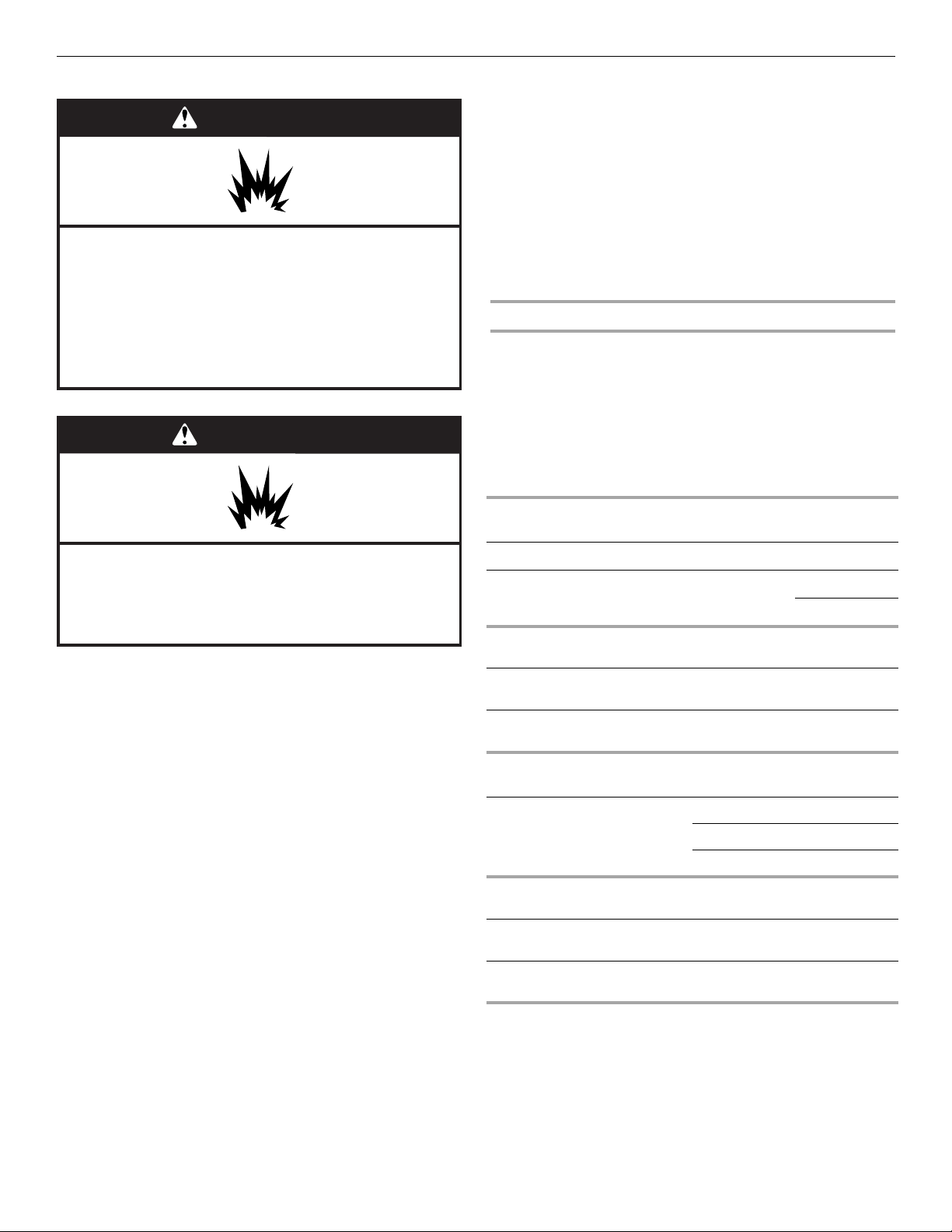
WARNING
Explosion Hazard
Keep flammable materials and vapors, such as
gasoline, away from furnace.
Place furnace so that burners are at least 18 inches
(46 cm) above the floor for a garage installation.
Failure to follow these instructions can result in death,
explosion, or fire.
WARNING
■ Furnaces may be installed as suspended units in the
horizontal position. These furnaces are not designed for
direct attachment of suspension rods to the furnace casing.
See “Installation Configurations.”
■ If the furnace is to be installed in an attic or other insulated
space, it must be kept free and clear of insulating materials.
■ WGFAT models may be installed as upflow or horizontal
furnaces. WGFAR models may be installed as counterflow
(downflow) or horizontal furnaces. When the furnace is
installed horizontally, secure the furnace door by installing a
sheet metal screw through the side and door on the upper
left-hand side of the furnace.
Installation Clearances
■ A 2" (5.1 cm) minimum clearance is required in front for air
openings into the combustion chamber.
■ All servicing and cleaning of the furnace can be performed
from the front. If the furnace is installed in a closet or utility
room, provide 24" (61 cm) clearance in front for service if the
door to the room is not in line with the front of the furnace.
Where servicing clearances are greater than clearances to
combustibles, servicing clearances take precedence.
Minimum Clearance to Combustibles Chart
All measurements in inches (centimeters)
Explosion Hazard
Do not install this furnace in a mobile home.
Doing so can result in death, explosion, fire, or
carbon monoxide poisoning.
IMPORTANT: Do not use the furnace as a heater in a building
under construction. The furnace can be severely damaged due to
the abnormal environment caused by construction. Chlorides
from sources such as paint, stain, or varnish; tile and counter
cements; adhesives; and foam insulation are abundant in a
structure under construction and can be highly corrosive. Low
return air temperature can cause condensation in the furnace and
other damage that can shorten the life of the furnace.
■ The furnace is suitable for installation in buildings
constructed on site. The furnace should be centralized in
respect to the heat distribution system as much as
practicable.
■ All models are suitable for closet or utility room installation.
Utility room installation requires:
A door opening large enough for the widest part of the
furnace.
A door opening large enough to remove/replace any other
appliance located in the utility room, such as a water heater.
Any other appliances arranged so that each appliance can be
removed/replaced without disturbing the furnace.
■ In a residential garage, a gas-fired furnace must be installed
so the burner(s) and the ignition source are located not less
than 18" above the floor. The furnace is to be located or
protected to avoid physical damage by vehicles.
Upflow Installations
Sides
Cabinet Width Front Back Top Vent Left Right
17¹⁄₂
(44.4)
21
(53.3)
24¹⁄₂
(62.3)
4
(10.2)
4
(10.2)
4
(10.2)
01
1
1
1
(2.5)6 (15.2)
01
(2.5)6 (15.2)
01
(2.5)6 (15.2)
2
2
(5.1)
00
2
00
2
0
3
Horizontal Installations
Minimum clearances on sides and back are 0".
Airflow
R to L L to R
Cabinet Width Front Vent Top Bottom Top Bottom
17¹⁄₂
(44.4)
21
(53.3)
24¹⁄₂
(62.3)
1
May be 2" (5.1 cm) when Type B-1 vent pipe is used.
2
May be 1" (2.5 cm) when Type B-1 vent pipe is used.
3
Where values greater than 0 are shown, may be 0" when Type
B-1 vent pipe is used.
18 6
18 6
18 6
(15.2)
(15.2)
(15.2)
1
2
(2.5)3 (7.6)
1
2
(2.5)2 (5.1)
1
2
(2.5)
3
(7.6)
2
(5.1)
0
2
0
3
2
3
000
4
Page 5
High Altitude Installations
B
■ This furnace is approved for operation at altitudes from 0 to
4,500 ft (0 to 1,371.6 m) above sea level without any required
modifications.
■ From 4,500 to 7,500 ft (1,371.6 m to 2,286 m), the gas
manifold pressure needs to be adjusted according to the
information shown in the Manifold Pressure vs. Altitude
Chart.
Installation Configurations
Upflow Installations
Furnaces can be installed with either a side or bottom air return.
For bottom air return the bottom air return knockout plate must
be removed. For furnaces that do not include a side or bottom
return filter rack, kit no. AFILT524-1 (side return) or kit no.
AFILT529-1 (bottom return) can be used.
To provide sufficient filter area for installations requiring more
than 1,600 CFM nominal air delivery, return air will have to be
brought through both sides of the furnace, or through one side
and the bottom.
Counterflow (Downflow) Installations
WARNING
IMPORTANT:
For installations above 7,500 ft (2,286 m), the furnace input rate is
to be reduced per the requirements of the National Fuel Gas
Code (ANSI Z223.1/NFPA 54, latest edition), at the rate of
4 percent for each 1,000 ft (304.8 m) above sea level.
The furnace is not recommended for installation above 10,000 ft
(3,048 m).
2. Construct duct connections with 1" to 1³⁄₄" (2.5 cm to 4.4 cm)
right-angle flanges, and long enough to extend below the
floor joists.
3. Drop the duct connections through the top of the base
assembly with the right-angle flanges secure against the
woven glass tape on the top of the base assembly.
4. Position the furnace over the right-angle duct flanges.
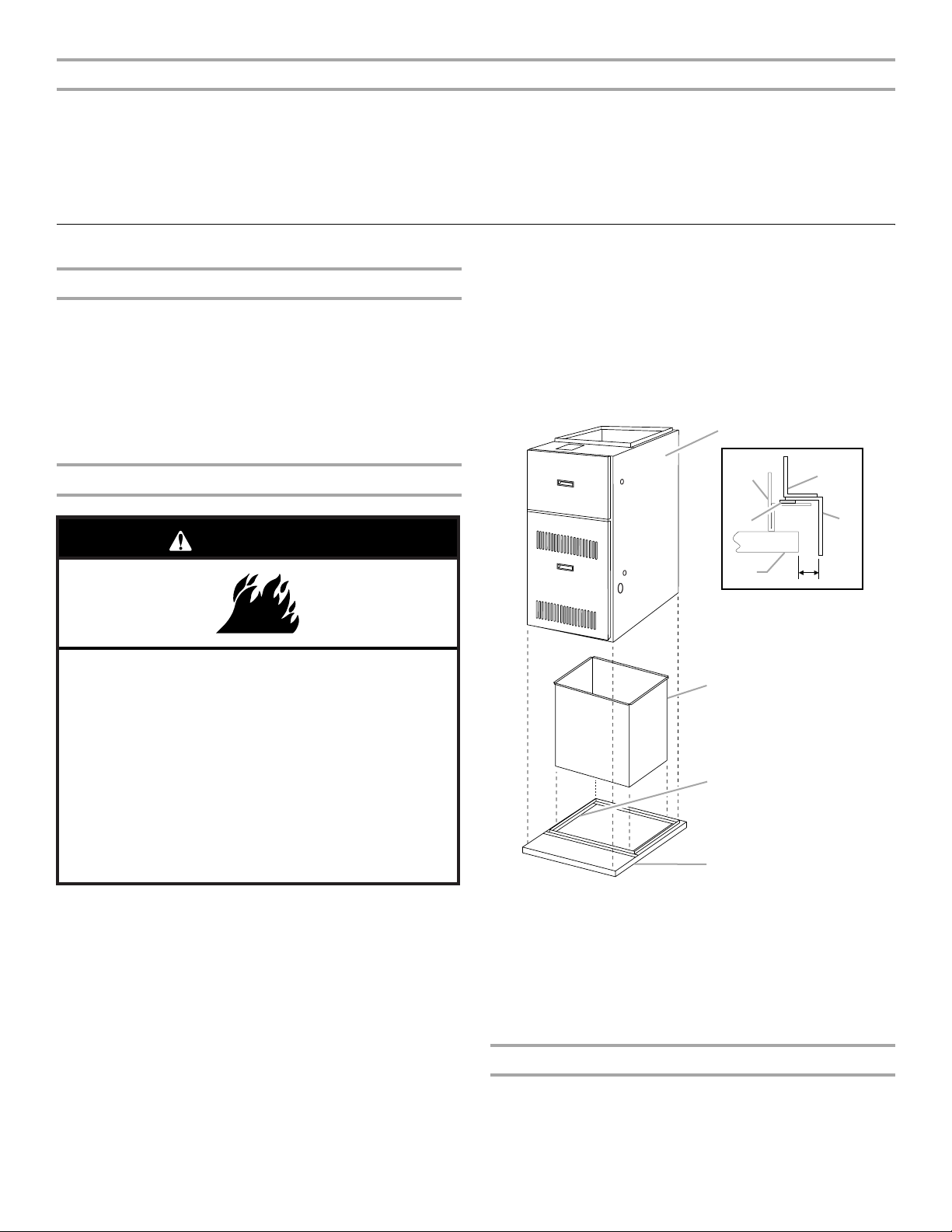
Combustible Floor Installation (Counterflow Models Only)
A
E
D
B
C
1"
Fire Hazard
Before installing counterflow (downflow) furnace on
combustible surface, such as wood, install one of the
following kits:
WABASE 511 (14.5" cabinets)
WABASE 512 (17.5" cabinets)
WABASE 568 (21" cabinets)
WABASE 569 (24.5" cabinets)
Contact your local dealer.
Failure to do so can result in death or fire.
IMPORTANT:
■ WGFAT and horizontally installed WGFAR models may be
installed on wood flooring, but should not be installed directly
on carpeting, tile or other combustible material.
■ WGFAR models installed as counterflow (downflow) models
may be installed on combustible flooring provided a special
combustible floor base is used.
■ For installations on combustible flooring, a special base must
be ordered and used. See the furnace rating plate for the
appropriate base model number.
■ WGFAR furnaces may be installed directly on the supply
plenum or coil cabinet if the furnace is installed on a
noncombustible floor.
1. Cut a hole in the floor, sized to provide 1" (2.5 cm) clearance
between all 4 sides of the duct and the edge of the flooring.
The 4 angles on the base assembly should recess into the
floor joists and the base should rest on all 4 outside flanges.
C
E
A
A. Base assembly
B. Furnace
C. Outlet duct (drops into
base assembly)
D. Combustible floor
E. Woven glass tape (between
flanges of outlet duct and
base assembly)
Filters
If a filter other than the one supplied by the furnace manufacturer
is used, see Minimum Filter Requirements in “Filter
Specifications.”
Horizontal Installations
Furnaces can be horizontally installed for airflow right to left or
left to right. To ensure access to parts for servicing, install upflow
and counterflow furnaces so that the burner and blower access
panels are readily accessible.
5
Page 6
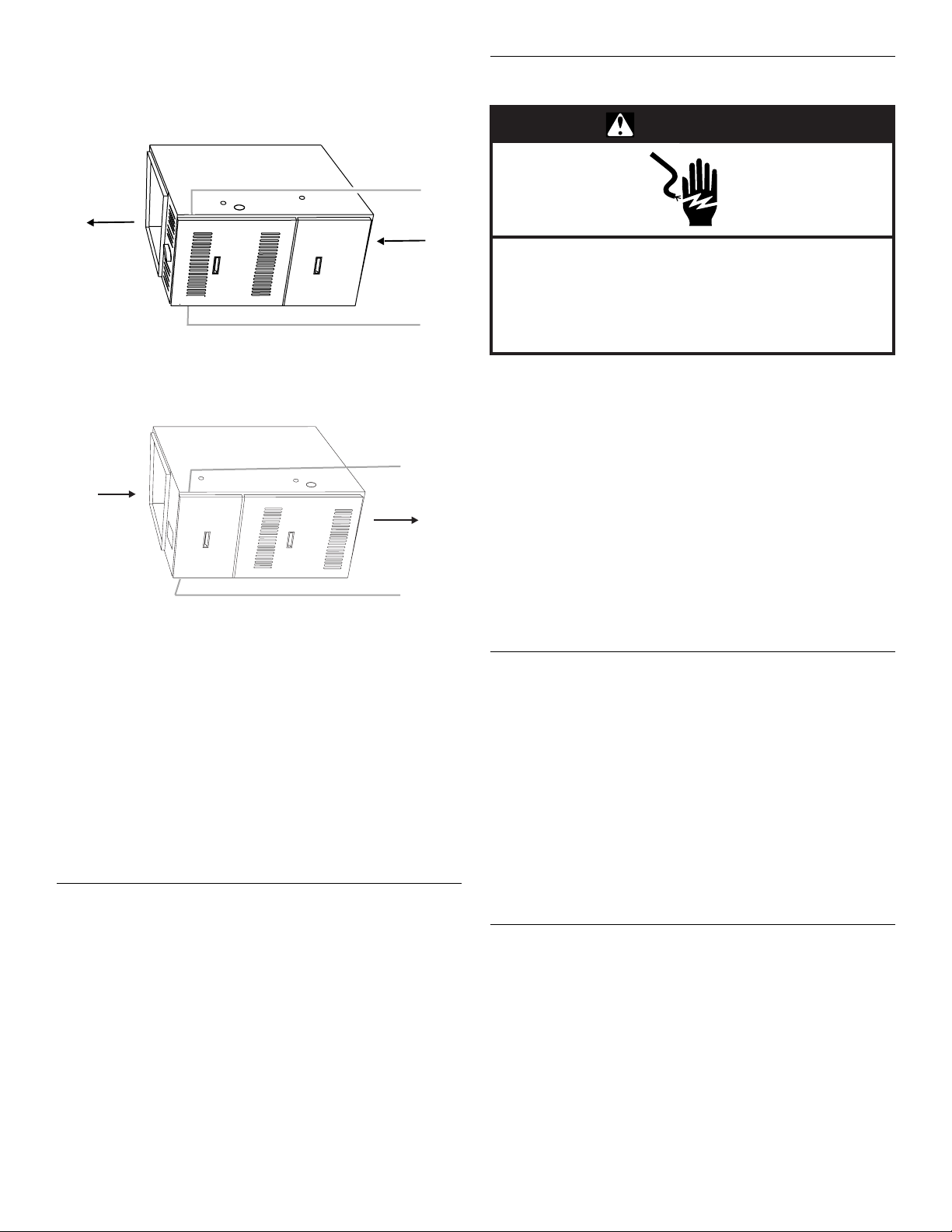
NOTE: When installed horizontally, the installer must install a
C
sheet metal screw to retain the upper door as shown following, in
either Position B or D, depending on installation configuration.
Electrical Requirements
Horizontal Installation—WGFAT Models
A
A. Outlet airflow
B. Screw placement for
Right to Left airflow
C. Inlet airflow
D. Screw placement for
Left to Right airflow
Horizontal Installation—WGFAR Models
A
A. Inlet airflow
B. Screw placement for
Left to Right airflow
C. Outlet airflow
D. Screw placement for
Right to Left airflow
WARNING
B
Electrical Shock Hazard
Electrically ground furnace.
Connect ground wire to green ground screw.
D
B
C
D
Failure to do so can result in death or electrical shock.
■ The furnace must be grounded and wired in accordance with
local codes or, in the absence of local codes, with the
National Electrical Code ANSI/NFPA No. 70 (latest edition).
■ In all instances, other than wiring for the thermostat, the
wiring to be done and any replacement of wire shall conform
with the temperature limitation for Type T wire (63°F [17ºC]
rise).
■ The line voltage supply should be routed through a readily
accessible disconnect located within sight of the furnace. A
junction box on the furnace side panel is provided for line
voltage connections. See the Wiring Connection Diagram in
the “Troubleshooting” section for specific connection
information.
■ Proper polarity of the supply connections (“HOT” and
“NEUTRAL”) must be observed to be sure that the control
system provides the protection intended.
Horizontal Installation—Suspended
Furnaces may be installed as suspended furnaces in the
horizontal position. These furnaces are not designed for direct
attachment of suspension rods to the furnace casing.
■ The suspending means must be field fabricated, and should
consist of 2 “cradles” made by attaching 2 rods to a length of
angle iron or suitable gauge steel.
■ Locate the cradles so that they are as close as possible to the
ends of the furnace (this will provide access for removal of
major components such as the blower assembly).
■ Provide enough clearance between the suspension rods and
the furnace to allow removal of access panels.
Ductwork Requirements
■ Install all conditioned air plenums, ducts and air filters (if not
provided on the furnace) in accordance with NFPA 90B
Standard for the Installation of Warm Air Heating and AirConditioning Systems (latest edition).
■ The furnace is provided with flanges for the connection of the
plenum and ducts.
■ All air filters must be listed as Class 2 furnace air filters.
■ All ductwork must be made of materials and insulated to
meet local, state and national codes. Ductwork installed
outdoors must be sealed, weatherproofed and protected
against physical damage. Caulking, flashing or other means
of adequately providing a permanent weather seal should be
used where duct penetrates a building or structure opening.
Gas Supply Requirements
This furnace is equipped for use with Natural gas. A conversion
kit is required for use with propane. To order the correct
conversion kit, see “Accessories.”
■ Gas supply piping should be installed in accordance with
local, state and national codes and the regulations of the
utility. Piping must be of adequate size to avoid undue
pressure drop. Consult the local utility or gas supplier for
complete details on special requirements for sizing gas
piping.
■ If local codes allow the use of a flexible gas appliance
connector, use a CSA design-certified outdoor flexible
stainless steel appliance connector or rigid gas supply line as
needed. Do not use a connector which has previously
serviced another gas appliance.
Venting Requirements
Adequate provisions for combustion air and ventilation of
furnace must be made. Refer to Section 5.3, “Air for
Combustion and Ventilation,” of the National Fuel Gas Code,
ANSI Z223.1/NFPA 54 (latest edition), or applicable provisions
of the local building codes. For Category 1 furnaces, vent
installations shall be in accordance with parts 7 and 11 of the
National Fuel Gas Code, ANSI Z223.1/NFPA 54, the local building
codes, and the furnace and vent manufacturer’s instructions.
6
Page 7
Existing Venting Systems
Venting Options
When an existing furnace is removed or replaced, the original
venting system may no longer be sized to properly vent the
attached appliances. An improperly sized venting system can
result in spillage of flue products into the living space, the
formation of condensate, leakage, etc. See the “Carbon
Monoxide Poisoning Hazard” for proper test procedure.
WARNING:
CARBON MONOXIDE POISONING HAZARD
Failure to follow the steps outlined below for each
appliance connected to the venting system being
placed into operation could result in carbon monoxide
poisoning or death.
The following steps shall be followed for each appliance
connected to the venting system being placed into operation,
while all other appliances connected to the venting system are
not in operation:
1. Seal any unused openings in the venting system.
2. Inspect the venting system for proper size and horizontal
pitch, as required in the National Fuel Gas Code,
ANSI Z223.1/NFPA 54 or the CSA B149.1, Natural Gas and
Propane Installation Codes and these instructions.
Determine that there is no blockage or restriction, leakage,
corrosion and other deficiencies which could cause an
unsafe condition.
3. As far as practical, close all building doors and windows
and all doors between the space in which the appliance(s)
connected to the venting system are located and other
spaces of the building.
4. Close fireplace dampers.
5. Turn on clothes dryers and any appliance not connected to
the venting system. Turn on any exhaust fans, such as
range hoods and bathroom exhausts, so they are operating
at maximum speed. Do not operate a summer exhaust fan.
6. Follow the lighting instructions. Place the appliance being
inspected into operation. Adjust the thermostat so
appliance is operating continuously.
7. Test for spillage from draft hood equipped appliances at the
draft hood relief opening after 5 minutes of main burner
operation. Use the flame of a match or candle.
8. If improper venting is observed during any of the above
tests, the venting system must be corrected in accordance
with the National Fuel Gas Code, ANSI Z223.1/NFPA 54
and/or CSA B149.1, Natural Gas and Propane Installation
Codes.
9. After it has been determined that each appliance connected
to the venting system properly vents when tested as
outlined above, return doors, windows, exhaust fans,
fireplace dampers and any other gas-fired burning
appliances to their previous conditions of use.
The furnace can be installed as either direct vent or nondirect
vent furnace.
For either type of installation, special venting considerations
must be followed. See “Determine Vent Pipe Direction” for the
type of furnace and venting being installed.
Direct Vent
A direct vent (two pipe) installation requires that all the air
necessary for combustion be supplied from outside the dwelling
through an air intake pipe.
■ All vents passing through floors, ceilings, and walls must be
installed in accordance with National Fuel Gas Code, ANSI
Z223.1/NFPA 54 (latest edition). In all applications in which
the flue pipe is run through an unconditioned space, ¹⁄₂"
insulation must be used over the pipe. In extremely cold
climates, ³⁄₄" (1.9 cm) insulation is recommended.
Nondirect Vent
A nondirect vent (one pipe) installation uses air from inside the
dwelling for combustion.
■ The furnace is shipped with the air inlet pipe terminated to the
top panel for either inside or outside combustion air. An inlet
air restrictor plate is supplied with this furnace and can be
found in the plastic bag containing these Installation
Instructions and the User’s Information Manual.
■ For installations using inside air for combustion (nondirect
vent), attach a 90° elbow (not supplied) to the inlet coupler
and install the restrictor plate inside the elbow. See “Plan
Vent System.”
Inlet Air Restrictor Plate
NOTE: The inlet air restrictor plate must be installed in all
installations that are nondirect vent.
Unconfined Space
An unconfined space is defined as “a space whose volume is
more than 50 cu. ft (1.4 m3) per 1,000 Btu/h of the combined input
rating of all appliances installed in that space.”
When a furnace is installed in an unconfined space in a building,
it can be assumed that the infiltration will be sufficient to supply
the required air.
If the furnace is installed in a ventilated attic or crawl space, it is
assumed that the air infiltration is sufficient to supply the required
combustion air. However, in a building of unusually tight
construction, additional outdoor air should be provided.
Confined Space
A confined space is defined as “a space whose volume is less
than 50 cu. ft (1.4 m
rating of all appliances installed in that space.”
NOTE: Choose a combustion air supply option. See “Plan Vent
System.”
3
) per 1,000 Btu/h of the combined input
7
Page 8
Contaminated Combustion Air
Excessive exposure to contaminated combustion air will result in
performance-related problems. The recommended source of
combustion air is outdoor air.
Outdoor air as the source of combustion air
If the furnace is installed in a confined space, it is recommended
that the necessary combustion air come from the outdoors by
way of an attic, crawl space, air duct, or direct opening.
Outdoor air is required as the source of combustion air when the
indoor air is contaminated with chemical substances and in the
following types of installations:
■ Furnaces installed in commercial buildings
■ Furnaces installed in buildings with indoor pools
■ Furnaces installed in hobby or craft rooms
■ Furnaces installed near chemical storage areas
■ Furnaces installed in laundry rooms
■ Furnaces installed in hair salons
Indoor air as the source of combustion air
Indoor air as the source of combustion air is acceptable in most
applications if the following guidelines are met:
■ All provisions for indoor combustion air must meet the
requirements for combustion air indicated in the National Fuel
Gas Code, ANSI Z223.1/NFPA 54 (latest edition), and/or any
applicable local codes.
■ If indoor combustion air is used, the air supply to the furnace
should not be exposed to the following substances:
Permanent wave solutions
Chlorinated waxes and cleaners
Chlorine-based swimming pool chemicals
Water softening chemicals
Deicing salts or chemicals
Carbon tetrachloride
Halogen-type refrigerants
Cleaning solvents (such as perchloroethylene)
Printing inks, paint removers, varnishes, etc.
Cements and glues
Antistatic fabric softeners for clothes dryers
Masonry acid washing materials
Chlorinated laundry products
Hydrochloric acid
INSTALLATION INSTRUCTIONS
WARNING
Explosion Hazard
Furnace must be installed and serviced by a
qualified person.
Examples of a qualified person include:
licensed heating personnel,
authorized gas company personnel.
Read and follow all instructions provided for
installation, adjustment, service, alteration, or
maintenance.
Failure to follow these instructions can result in death,
explosion, fire, or carbon monoxide poisoning.
Inspect Shipment
WARNING
Excessive Weight Hazard
Use two or more people to move and install furnace.
Failure to do so can result in back or other injury.
1. Check the furnace rating plate to confirm specifications are
as ordered.
2. Upon receipt of the furnace, inspect it for possible shipping
damage. Examine the furnace inside the carton if the carton
is damaged.
If damage is found, it should be noted on the carrier’s freight bill.
Damage claims should be filed with the carrier immediately.
Claims of shortages should be filed with the seller within 5 days.
NOTE: If any damages are discovered and reported to the carrier,
do not install the furnace, because your claim may be denied.
Plan Vent System
IMPORTANT: The venting system must be supported with
mounting straps to avoid any weight load from being applied to
the vent blower. Horizontal vent pipe must be supported every
5 ft (1.5 m) and vertical pipe should be supported every 10 ft
(3 m) to avoid sagging and provide rigid support.
Materials—Air Intake Pipe Only
■ All pipe, fittings, primer, and solvent cement must conform
with American National Standard Institute and the American
Society for Testing and Materials (ANSI/ASTM) standards.
The solvent shall be free flowing and contain no lumps,
undissolved particles, or any foreign matter that adversely
affects the joint strength or chemical resistance of the
cement. The cement shall show no gelatinization,
stratification, or separation that cannot be removed by
stirring. See Piping and Fitting Specifications for approved
piping and fitting materials.
This furnace is shipped in one package, completely assembled
and wired. The indoor thermostat and accessories are shipped in
a separate carton when ordered.
8
Page 9

Piping and Fitting Specifications
E
D
Piping and Fitting Material ASTM Specification
Schedule 40 PVC (Pipe) D1785
Schedule 40 PVC (Cellular Core Pipe) F891
Schedule 40 PVC (Fittings) D2466
SDR-26 (Pipe) D2241
Schedule 40 ABS (Pipe) D1527
Schedule 40 ABS (Fittings) D2468
Schedule 40 & 80 CPVC (Pipe) F441
ABS-DWV Drain Waste & Vent
(Pipe & Fittings)
PVC-DWV Drain Waste & Vent
(Pipe & Fittings)
■ The primers and solvents used must also meet ASTM
specifications. PVC primer is specified in ASTM F656. Use
PVC solvent as specified in ASTM D2564 and ABS solvent
cement as specified ASTM D2235. Low temperature solvent
cement is recommended. Metal or plastic strapping may be
used for vent pipe hangers.
■ When making ABS joints, pieces can be prepared with a
cleaner. When joining ABS to PVC materials, use PVC solvent
cement as specified in ASTM D3138.
■ Preferred fittings are DWV style or long sweep. Seal all joints
gas tight with appropriate cement. In areas where vent and air
intake pipes are exposed to abnormal stress or are subject to
damage, schedule 80 pipe should be used.
■ Use high temperature RTV silicone sealant to attach the air
intake pipe into the connector on the burner box so the air
intake pipe can be removed if service is required.
NOTE: Do not use cement.
D2661
D2665
Typical Installation—Vertical Vent with Outdoor Fresh Air
B
A
C
E
F
A. Approved vent system
B. 65 ft (19.8 m) maximum
C. 6" (15.2 cm) minimum
D. Inlet located away from obstructions
and maximum snow level
E. 12" (30.5 cm) maximum
F. PVC inlet pipe
(see Inlet Pipe
Specifications chart)
Inlet Pipe Specifications
Inlet Pipe
Input—KBtu/h Inlet Pipe Size
50 2" (5.1 cm) 65 ft (19.8 m)
75 & 100 2" (5.1 cm) 30 ft (9.1 m)
75, 100, 125 & 150 3" (7.6 cm) 65 ft (19.8 m)
*The inlet air lengths listed are maximum “equivalent pipe
lengths.”
NOTE: One 90º elbow or two 45º elbows are the equivalent of 5 ft
(1.5 m) of pipe.
Total Length*
Confined Space Installation—Direct Venting
■ If the furnace is installed in a confined space and all the air
necessary for combustion is supplied to the furnace through
an air intake pipe vented directly outside, the pipe size and
materials used must conform to the specification listed in
“Materials—Air Intake Pipe Only.”
Confined Space Installation—Direct Venting
B
A
H
A. Chimney or gas vent
B. Approved vent
C. 65 ft (19.8 m) maximum
D. 6" (15.2 cm) minimum
E. Inlet located away from obstructions
and maximum snow level
F. 12" (30.5 cm) maximum
G. Air intake pipe
H. Furnace
C
D
F
G
Optional Attic Inlet Air
NOTE: Attic must be well ventilated.
A
F
E
D
A. Gable vent
B. 12" (30.5 cm) maximum
C. Gas furnace
B
C
D. Gas water heater
E. Joist and insulation
F. Soffit vent
9
Page 10

Optional Outside Air
C
C
D
C
B
D
E
F
E
D
A
B
Outside
If air from outside is brought in for combustion, the confined
space shall be provided with 2 permanent openings. One
opening shall be within 12" (30.5 cm) of the ceiling and 1 opening
within 12" (30.5 cm) of the floor. Several methods can be used to
bring the outside air in through these openings. The openings
must open directly or by ducts to the outdoors, through spaces
(crawl space or attic) that freely open to the outdoors, or
indirectly through vertical ducts.
NOTE: If any of these methods are used, the inlet and outlet air
openings must each have a free area of 1 sq. in. (6.4 cm
4,000 Btu/h of the total input rating of all equipment within the
enclosure.
2
) per
Equipment in Confined Space—All Air from Outside
Confined Space Installation—Nondirect Venting Air from
C
(Inlet air from crawl space and outlet air to ventilated attic)
A. Gable vent
B. 16" to 24" (40.6 cm to 61 cm)
C. Gas furnace
D. Gas water heater
E. Joist and insulation
F. So f fit v en t
NOTE: The actual height of the roof termination should be 12"
(30.5 cm) above the average snow accumulation.
Confined Space Installation—Nondirect Venting Air from
Inside
If the furnace is installed in a confined space within the building
and combustion air is taken from a heated space, the
combustion air and ventilating air must enter and leave the space
through 2 permanent openings of equal area. One opening shall
be located within 12" (30.5 cm) of the ceiling and the other within
12" (30.5 cm) of the floor.
NOTE: Each opening must have a free area of at least 1 sq. in.
2
(6.4 cm
the enclosure, and not less than 100 sq. in. (645 cm
) per 1,000 Btu/h of total input rating of all equipment in
2
) each.
Equipment in Confined Space—All Air from Inside
B
A
A
G
F
A. Chimney or gas vent
B. Ventilation louvers (each end of attic)
C. Outlet air
D. Water heater
E. Inlet air
F. Ventilation louvers
(for unheated crawl space)
G. Furnace
Equipment in Confined Space—All Air from Outside
(All air through ventilated attic)
A
B
E
10
F
D
A. Chimney or gas vent
B. Water heater
C. Openings
D. Furnace
A. Chimney or gas vent
B. Ventilation louvers
(each end of attic)
C. Outlet air
D. Inlet air (ends 12" (30.5 cm) above
bottom)
E. Water heater
F. Furnace
Page 11
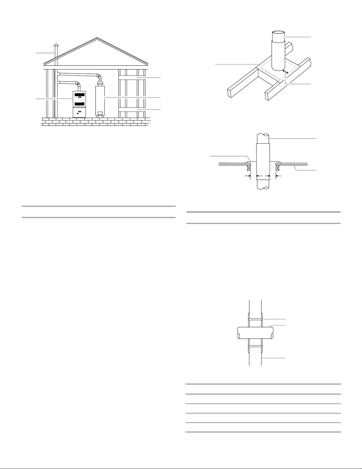
Equipment in Confined Space—All Air from Outside
C
B
C
B
C
A
B
C
(All air from horizontal ducts)
A
B
E
D
A. Chimney or gas vent
B. Outlet air
C. Water heater
NOTE: Another option is to use horizontal combustion ducts. If
horizontal combustion ducts are run, 1 sq. in. (6.4 cm2) per
2,000 Btu/h of the total input rating of all equipment in the
enclosure is required. If the equipment room is located against an
outside wall and the air openings communicate directly with the
outdoors, each opening shall have a free area of at least 1 sq. in.
2
(6.4 cm
) per 4,000 Btu/h of the total input rating of all other
equipment in the enclosure.
D. Inlet air
E. Furnace
Vent Option—Vent Through Ceiling
A
A. 26 gauge galvanized firestop
on top of framed opening
B. Flue pipe
Vent Option—Vent Through Floor
A
D
A. Pipe collar (firestop)
B. Flue pipe
D
C. 1" (2.5 cm) clearance
between flue pipe and
frame
C. Floor
D. 1" (2.5 cm)
Vertical Venting
Category I furnaces must be vented vertically or nearly vertically.
Common venting and multistory venting are permitted when
done in accordance with applicable codes, such as local and
national codes.
The venting system should be designed in accordance with the
“FAN” columns in the venting tables in the latest editions of the
National Fuel Gas Code, ANSI Z223.1/NFPA 54.
■ Consult local building codes for installation requirements.
■ The vent connector should be as short as possible with the
least number of elbows and angles to do the job.
■ It is recommended that a minimum of 26-gauge galvanized
flue pipe be used. Use of single-wall vent pipe for the vent
connector is permissible only in conditioned space. The vent
material used should be in accordance with the National Fuel
Gas Code, ANSI Z223.1/NFPA 54 (latest edition) and local
codes. Fan-assisted combustion system Category I furnaces
shall not be vented into single wall metal vents.
NOTE: Use Doublewall Type B vent pipe through
unconditioned space such as attics and crawl spaces.
■ The vent connector must have an upward slope toward the
chimney on all horizontal runs of at least ¹⁄₄" (6.4 mm) per ft of
horizontal run and should be supported by a sheet metal
strap. The vent pipe connection must be secured to the
induced draft blower outlet.
■ All vents passing through floors, ceilings, and walls must be
fire stopped according to the requirements of the National
Fuel Gas Code. See vent options.
Sidewall Venting
This furnace can be sidewall (horizontally) vented with a listed
sidewall venter such as Field Controls Model SWG-4HD with CK43 Control Kit, or Tjernlund Model GPAK-JT. See the Sidewall
Venter Limitations Chart following.
Category I venting classification is maintained when vented in
this manner. The furnace, power venter and control kit (where
applicable) must be installed in accordance with their installation
instructions and all applicable codes.
For horizontal runs of vent pipe, supports are required at 5 ft
(1.5 m) intervals.
Vent Through Wall
A. Thimble
B. Flue pipe
C. Combustible wall
Sidewall Venter Limitations Chart
Vent pipe diameter 4" (10.2 cm)
Minimum vent pipe length 48" (121.9 cm)
Maximum vent pipe length 25 ft* (7.6 m)
Maximum number of 90° elbows 4
*When fewer than 4 elbows are used, maximum vent pipe length
can be increased by 5 ft (1.5 m) per unused elbow.
11
Page 12
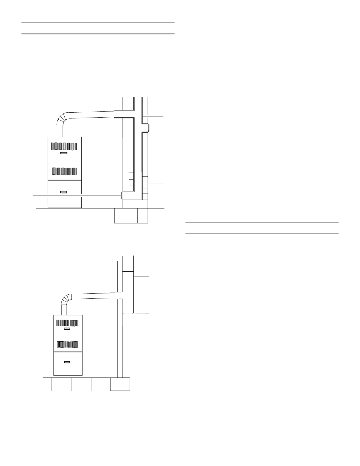
Chimney Options
C
A
B
The furnace must be connected to a factory-built chimney or vent
complying with a recognized standard, or a masonry or concrete
chimney lined with a lining material acceptable to the authority
with jurisdiction.
NOTE: Venting into an unlined masonry chimney or a single wall
metal vent is prohibited in all cases. A lined masonry chimney
may be used.
Lined (Masonry) Chimney Venting
B
A
■ Extend the vent connector into the chimney so that it is flush
with the inside of the flue liner. Seal the joint between the pipe
and the liner.
■ Masonry chimneys serving fireplaces cannot be used for
venting purposes unless the fireplace opening is permanently
sealed.
■ A vent connector serving this appliance must not be
connected into any portion of mechanical draft systems
operating under positive pressure.
■ The vent pipe must not be connected to a chimney flue
serving a solid fuel appliance.
■ A manual damper, barometric draft regulator, or flue restrictor
must not be installed between the furnace and the chimney.
■ Where local experience indicates that condensate may be a
problem, the vent shall be constructed to avoid condensation
from entering the combustion blower. Provision shall be
made to drain off the condensate.
■ All unused chimney openings should be closed.
■ Multistory venting is allowed as permitted by the National
Fuel Gas Code or local codes.
■ Install all vents in accordance with the vent manufacturer’s
instructions. For unlisted materials, install in accordance with
the National Fuel Gas Code.
■ Vent terminals must be installed in accordance with the vent
terminals listing or in accordance with the National Fuel Gas
Code, ANSI Z223.1/NFPA 54 (latest edition), and local codes.
Determine Vent Pipe Direction
The vent system of the furnace must be self-supporting and must
not apply any weight load to the combustion blower.
A. Cleanout
B. Liner
C. Lined masonry chimney
Factory-Built Chimney Venting
A. Factory-built chimney
B. Cleanout
Combustion Air Sources
There are 2 sources for combustion air:
1. From outside the building (Direct Vent)
2. From inside the building (Nondirect Vent)
Please read the information provided here about Vertical and
Horizontal Venting, then find and follow the instructions for your
venting configuration.
Vertical Venting
A vertical vent should extend through the roof a minimum of 24"
(5.1 cm) and not be obstructed a minimum of 10 ft (3 m) in any
direction.
Horizontal Venting
The vent terminal location shall comply with the National Fuel
Gas Code (ANSI Z223.1) or local requirements. For informational
purposes, the side wall terminal vent clearances are shown in the
Sidewall Vent Terminal Clearances tables.
NOTE: All vent pipe run outside shall be constructed of
factory-built chimney sections.
12
Page 13
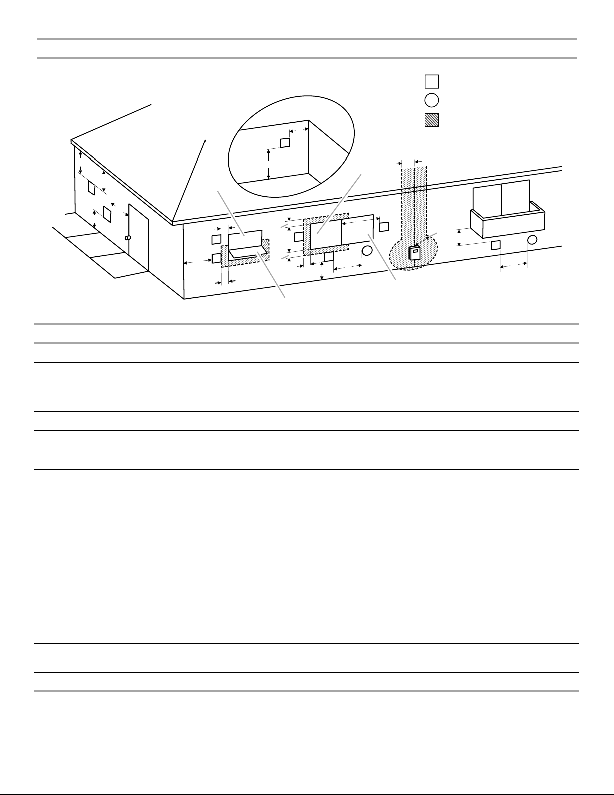
Sidewall Vent Terminal Clearances—Direct Vented Furnaces (Horizontal Venting)
Inside
Corner Detail
G
V
Vent Terminal
V
Air Supply Intake
X
Area Where Terminal Is
Not Permitted
V
1
H
Fixed
Closed
I
M
V
X
K
D
E
V
B
V
L
Fixed
Closed
C
V
V
F
A
Operable
B
B
V
B
V
B
A
X
J
B
Operable
U.S. Installations
A Clearance above grade, veranda, porch, deck, or balcony 12" (30.5 cm)
B Clearance to window or door that may be opened 6" (15.2 cm) for appliances less than 10,000 Btu/h, 9" (22.9 cm)
for appliances greater than 10,000 Btu/h, and less than or equal to
50,000 Btu/h, 12" (30.5 cm) for appliances greater than
50,000 Btu/h
C Clearance to permanently closed window *
D Vertical clearance to ventilated soffit located above the
*
terminal within a horizontal distance of 24" (61 cm) from the
center line of the terminal
E Clearance to unventilated soffit *
F Clearance to outside corner *
G Clearance to inside corner *
H Clearance to each side of center line extended above meter/
*
regulator assembly
I Clearance to service regulator vent outlet *
J Clearance to nonmechanical air supply inlet to building or
the combustion air inlet to any other appliance
6" (15.2 cm) for appliances less than or equal to 10,000 Btu/h, 9"
(22.9 cm) for appliances greater than 10,000 Btu/h, and less than
or equal to 50,000 Btu/h, 12" (30.5 cm) for appliances greater than
50,000 Btu/h
K Clearance to a mechanical air supply inlet 36" (91.4 cm) above if within 10 ft (3 m) horizontally
L Clearance above paved sidewalk or paved driveway located
*
on public property
M Clearance under veranda, porch, deck, or balcony *
1
In accordance with the current ANSI Z2223.1/NFPA 54, National Fuel Gas Code.
*Clearance in accordance with local installation codes and the requirements of the gas supplier and the manufacturer’s installation
instructions.
13
Page 14
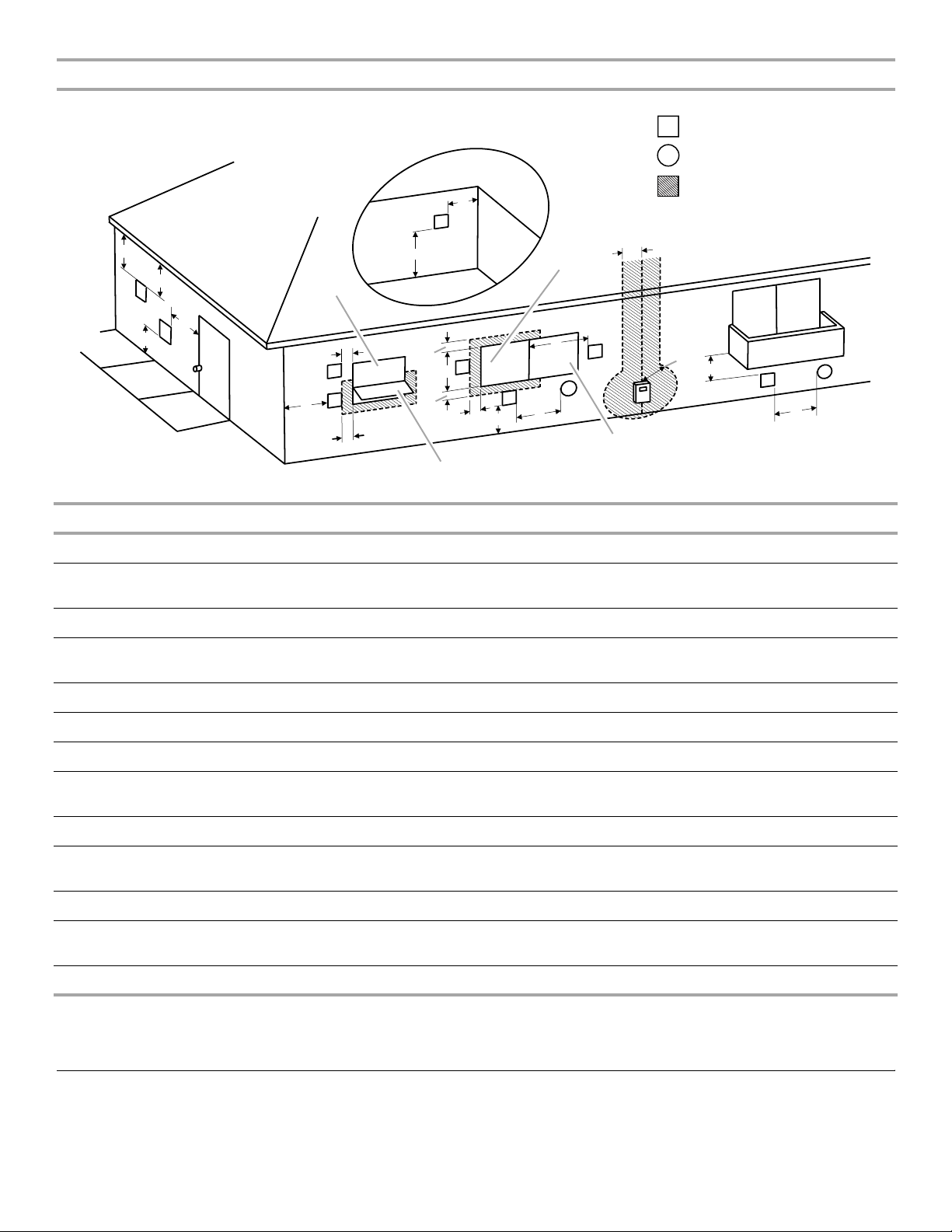
Sidewall Vent Terminal Clearances—Nondirect Vented Furnaces (Horizontal Venting)
Inside
Corner Detail
G
V
Vent Terminal
V
Air Supply Intake
X
Area Where Terminal Is
Not Permitted
V
H
Fixed
Closed
I
M
V
X
K
1
D
E
V
B
V
L
Fixed
Closed
C
V
V
F
A
Operable
B
B
V
B
V
B
A
X
J
B
Operable
U.S. Installations
A Clearance above grade, veranda, porch, deck, or balcony 12" (30.5 cm)
B Clearance to window or door that may be opened 48" (121.9 cm) below or to side of opening; 12"
(30.5 cm) above opening
C Clearance to permanently closed window *
D Vertical clearance to ventilated soffit located above the terminal within a
*
horizontal distance of 24" (61 cm) from the center line of the terminal
E Clearance to unventilated soffit *
F Clearance to outside corner *
G Clearance to inside corner *
H Clearance to each side of center line extended above meter/regulator
*
assembly
I Clearance to service regulator vent outlet *
J Clearance to nonmechanical air supply inlet to building or the combustion
air inlet to any other appliance
48" (121.9 cm) below or to side of opening; 12"
(30.5 cm) above opening
K Clearance to a mechanical air supply inlet 36" (91.4 cm) above if within 10 ft (3 m) horizontally
L Clearance above paved sidewalk or paved driveway located on public
7 ft (2.1 m)
property
M Clearance under veranda, porch, deck, or balcony *
1
In accordance with the current ANSI Z2223.1/NFPA 54, National Fuel Gas Code.
*Clearance in accordance with local installation codes and the requirements of the gas supplier and the manufacturer’s installation
instructions.
Connect Venting
1. Using a ¹⁄₄" (6.4 mm) sheet metal screw, secure the vent pipe
to the inducer blower outlet.
2. Make sure all vent connections do not leak.
3. Check that the venting is open, and that it is the correct size.
4. Check that the vent pipe terminates outside the building.
14
Page 15
Install Ductwork
B
IMPORTANT:
■ Install ductwork in accordance with NFPA 90B and any local
codes.
■ When the furnace is installed so that the supply ducts carry
air circulated by the furnace to areas outside the space
containing the furnace, the return air shall be handled by a
duct or ducts sealed to the furnace casing and terminated
outsides the space containing the furnace to avoid a negative
pressure on the venting system.
■ If there is no complete return air duct system, the return air
connection must be sealed to the furnace casing and run full
size to a location outside the utility room or space housing
the furnace to avoid a negative pressure on the venting
system.
Installation with an Evaporator Coil
IMPORTANT: When an air conditioning unit is used in
conjunction with the furnace, the evaporator coil must be
installed in the discharge (supply) air. Do not install an evaporator
coil in the return air; excessive condensation will occur within the
furnace.
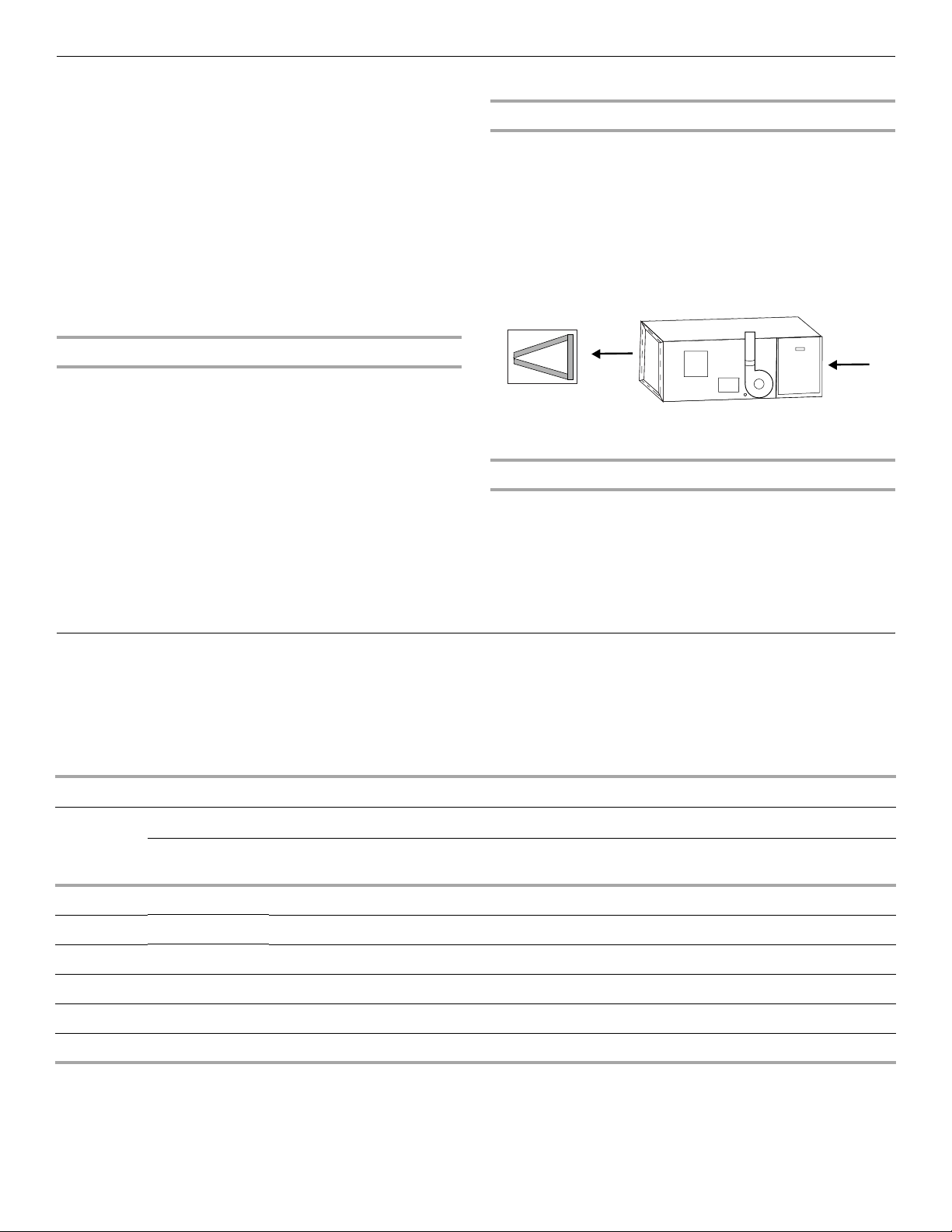
When installing a WEC coil in a horizontal position with a
horizontal gas furnace, the open end of the A-coil must face the
supply air outlet of the furnace (blow into the open end of the Acoil). The A-coil should point away from the supply air outlet of
the furnace as shown.
Installation with Return Ducts
A return air duct system is recommended. If the furnace is
installed in a confined space or closet, a return connection must
be run, full size, to a location outside the closet. The air duct in
the closet must be tight to avoid any entrance of air from the
closet into the circulating air.
Filter Specifications
Filters are not supplied with these furnaces. It is the furnace
installer’s responsibility to install properly sized filters in
accordance with the Minimum Filter Requirements Chart.
■ The Airflow Descriptor is the 2 digits immediately preceding
the hyphen (-) in the furnace model number. The model
number is located on the rating plate inside the access panel.
Minimum Filter Requirements Chart
A
A. Supply
B. Return
Installation without an Evaporator Coil
If a cooling coil is not installed with the furnace, then a removable
access panel should be provided in the supply plenum for
purposes of inspecting the heat exchanger. This opening must be
accessible when the furnace is installed. It must be large enough
that the heat exchanger can be viewed for possible openings
using light assistance or so that a probe can be inserted for
sampling the airstream. The cover for the opening must be leak
tight.
■ Areas and dimensions shown for cleanable filters are based
on filters rated at 600 ft (182.9 m) per minute face velocity.
■ Typical filter sizes are shown; however, any combination of
filters whose area equals or exceeds the minimum area
shown is satisfactory.
Disposable Filters Cleanable Filters
Airflow
Descriptor
09 480 (3,096.8) 20 x 25 (50.8 x 63.5) 1 240 (1,548.4) 16 x 20 (40.6 x 50.8) 1
10 480 (3,096.8) 20 x 25 (50.8 x 63.5) 1 240 (1,548.4) 16 x 20 (40.6 x 50.8) 1
12 576 (3,716.1) 16 x 20 (40.6 x 50.8) 2 288 (1,858.1) 16 x 20 (40.6 x 50.8) 1
14 672 (4,335.5) 20 x 20 (50.8 x 50.8) 2 336 (2,167.7) 20 x 20 (50.8 x 50.8) 1
16 768 (4,954.8) 20 x 20 (50.8 x 50.8) 2 384 (2,477.4) 20 x 20 (50.8 x 50.8) 1
20, 22 960 (6,193.5) 20 x 25 (50.8 x 63.5) 2 480 (3,096.8) 20 x 25 (50.8 x 63.5) 1
If a central return air filter-grille is used, the furnace does not
require a filter.
To install a filter at the furnace only, use the following kits:
Minimum Area—
sq. in. (cm
2
) Size—in. (cm) Quantity
Minimum Area—
sq. in. (cm2) Size—in. (cm) Quantity
■ AFILT524 for side return on upflow installations.
■ AFILT529 for bottom return on upflow furnace installations.
15
Page 16
Make Electrical Connections
A
WARNING
Electrical Shock Hazard
Disconnect power before servicing.
Replace all parts and panels before operating.
Failure to do so can result in death or electrical shock.
Thermostat
Install a room thermostat according to the instructions furnished
with it. Select a location on an inside wall that is not subject to
drafts, direct sunshine, or other heat sources.
Make the low voltage thermostat connections to the ignition
control board as indicated on the Wiring Connection Diagram in
“Troubleshooting.”
1. Disconnect power.
2. Remove the screw from the furnace electrical connection
box.
3. Remove the cover from the furnace electrical connection box.
4. Route the field supply wires to the furnace electrical
connection box.
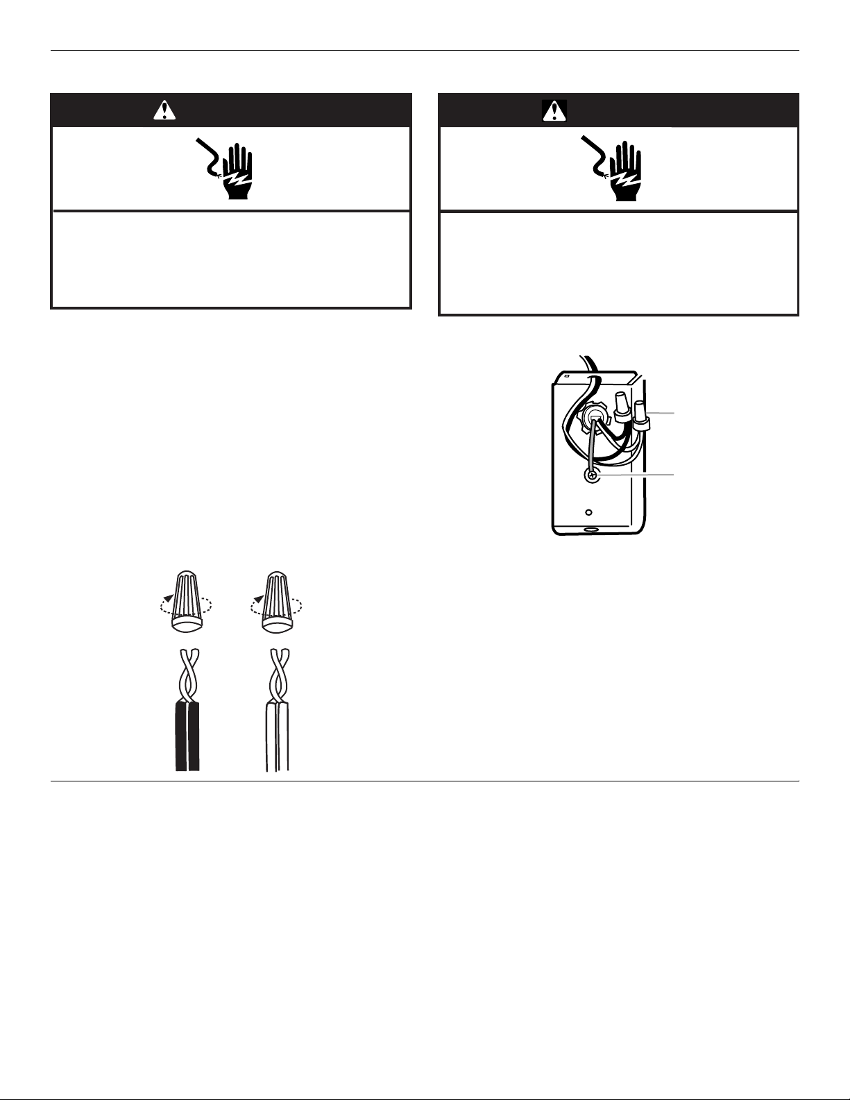
5. Using UL listed wire connectors, connect the field supply
wires to the furnace (black to black and white to white).
WARNING
Electrical Shock Hazard
Electrically ground furnace.
Connect ground wire to green ground screw.
Failure to do so can result in death or electrical shock.
6. Connect ground wire to green ground screw.
B
A. Connect white to white and black to black
B. Green ground screw
Make Gas Connections
IMPORTANT: This furnace requires conversion for use with
propane. To order the correct conversion kit, see “Accessories.”
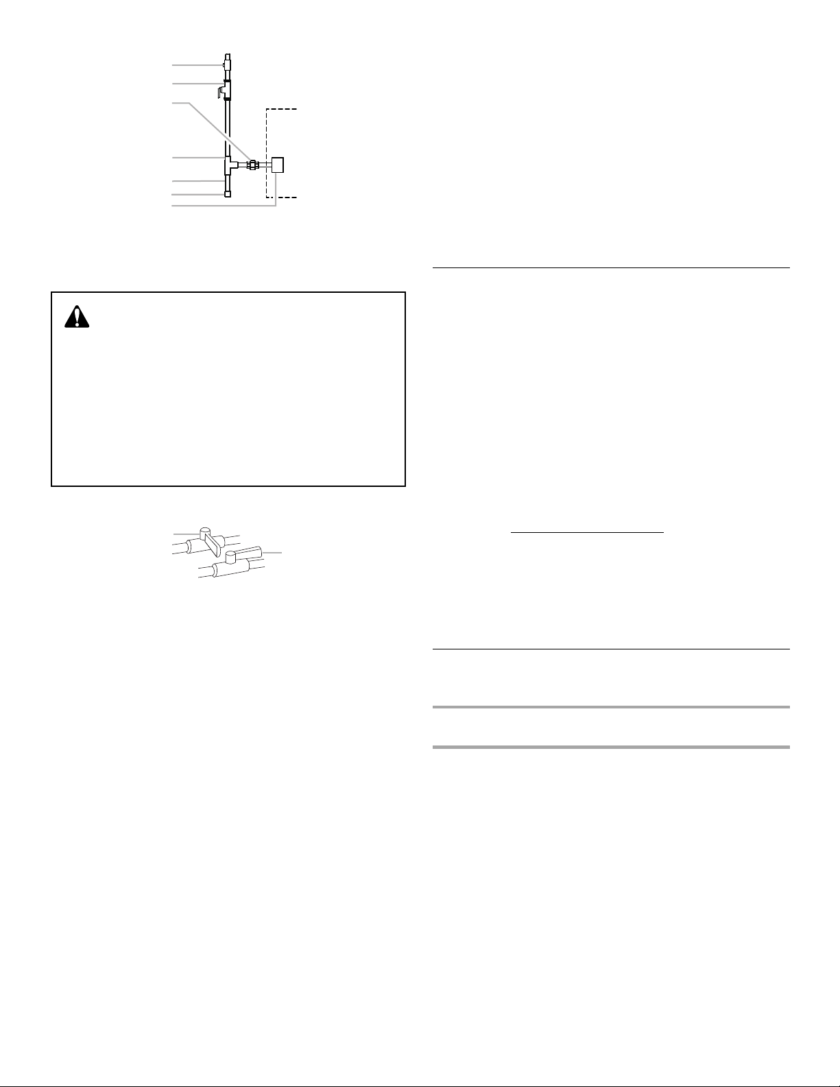
1. Install the field gas supply as shown.
2. Provide a sediment trap on the outside of the furnace.
3. Install a manual gas shutoff valve in the gas line, outside the
furnace, 5 ft (1.5 m) above the floor, or in accordance with any
local codes.
7. Replace the furnace electrical connection box cover and
screw.
4. Install a test gauge connection with a ¹⁄₈" (3.2 mm) NPT
plugged tap immediately upstream of the manual gas shutoff
valve as shown.
5. Connect the gas pipe to the furnace controls providing a
ground joint union as close to the controls as possible to
facilitate removal of controls and manifold.
Pipe-joint compounds suitable for use with Natural and LP
gas must be used. Do not use Teflon
®
tape.
16
Page 17
A
B
C
D
E
F
G
A.
¹⁄₈
" (3.2 mm) NPT plugged tap
B. Manual gas shutoff valve
C. Ground joint union
D. Tee
E. Sediment trap
F. C a p
G. Gas control valve
(inside furnace)
WARNING
FIRE OR EXPLOSION HAZARD
Failure to follow the safety warnings exactly could result
in serious injury, death or property damage.
Never test for gas leaks with an open flame. Use a
commercially available soap solution made specifically
for the detection of leaks to check all connections. A fire
or explosion may result causing property damage,
personal injury or loss of life.
6. Turn off the gas supply at the manual gas shutoff valve.
A
B
A. Closed valve
B. Open valve
7. Remove the inlet pressure tap plug on the gas control valve
and connect pressure gauge to the ¹⁄₈" NPT inlet
pressure tap.
8. Turn on the gas supply at the manual gas shutoff valve.
9. Observe the inlet pressure.
The minimum inlet gas supply pressure is 5" (12.7 cm) W.C.
for Natural gas and 11" (27.9 cm) W.C. for propane gas.
The maximum inlet gas supply pressure is 10¹⁄₂" (26.7 cm)
W.C. for Natural gas and 13" (33 cm) W.C. for propane gas.
10. Turn off the gas supply at the manual gas shutoff valve.
IMPORTANT: If the inlet gas supply pressure is not within the
minimum and maximum range as shown on the rating plate,
contact your gas supplier.
11. Disconnect the pressure gauge from the ¹⁄₈" (3.2 mm) NPT
inlet pressure tap.
12. Replace the inlet pressure tap plug on the gas control valve.
13. Turn on the gas supply at the manual gas shutoff valve.
14. Test all connections by brushing on an approved
noncorrosive leak-detection solution. Bubbles will show a
leak. Correct any leak found.
■ At test pressures greater than ¹⁄₂ psig (3.5 kPa), the
furnace and the manual gas shutoff valve must be
disconnected from the gas supply piping system.
■ At test pressures less than or equal to ¹⁄₂ psig (3.5 kPa),
the furnace must be isolated from the gas supply piping
system by closing the manual gas shutoff valve.
15. Replace the burner access door.
Check the Furnace Input Rate
(if required)
IMPORTANT:
■ The furnace input rate must not exceed the input rating on
the furnace rating plate.
■ This furnace is equipped for rated input at manifold pressures
of 1.7" (4.32 cm) W.C. (1
(2ndstage) for Natural gas. When an LP conversion kit is used,
it is equipped for rated input at manifold pressures of 4.9"
(12.45 cm) W.C. (1
for propane gas.
■ For natural gas, check the furnace rate by observing the gas
meter, making sure all other gas appliances are turned off.
The test hand on the meter should be timed for at least one
revolution.
Btu/h
Input
■ At altitudes from 2,000 to 7,500 ft (609.6 m to 2,286 m) the
= Cu. ft per Revolution x 3600 x Heating
# Seconds per Revolution
furnace input rate must not exceed that on the rating plate.
NOTE: The actual heating value of your gas can be obtained from
your local utility company. Typical values are shown in the
Manifold Pressure vs. Altitude Chart in “Adjust the Furnace Input
Rate.”
st
stage) and 3.5" (8.9 cm) W.C.
st
stage) and 10" (25.4 cm) W.C. (2ndstage)
Value
Adjust the Furnace Input Rate
(if required)
For Altitudes 4,500 to 7,500 ft (1,371.6 m to 2,286 m)
Above Sea Level
1. Remove the burner access door.
2. Turn the gas control to the OFF position. Use only your hand
to move the gas control; tools are not required.
3. Remove the outlet pressure tap plug on the gas control valve
and connect pressure gauge to the ¹⁄₈" (3.2 mm) NPT outlet
pressure tap.
®Teflon is a registered trademark of E.I. Dupont de Nemours and
Company.
17
Page 18
Gas Control Valve
B
H
IMPORTANT: If the manifold pressure cannot be adjusted to
A
the correct value, contact your gas supplier.
10. Move the gas control to the OFF position.
11. Disconnect the pressure gauge from the ¹⁄₈" (3.2 mm) NPT
outlet pressure tap.
12. Replace outlet pressure tap plug and the regulator adjusting
cap on the gas control valve.
13. Move the gas control to the ON position.
14. Replace the burner access door.
15. Set the room thermostat to the desired temperature
necessary to achieve optimum temperature rise.
G
C
F
E
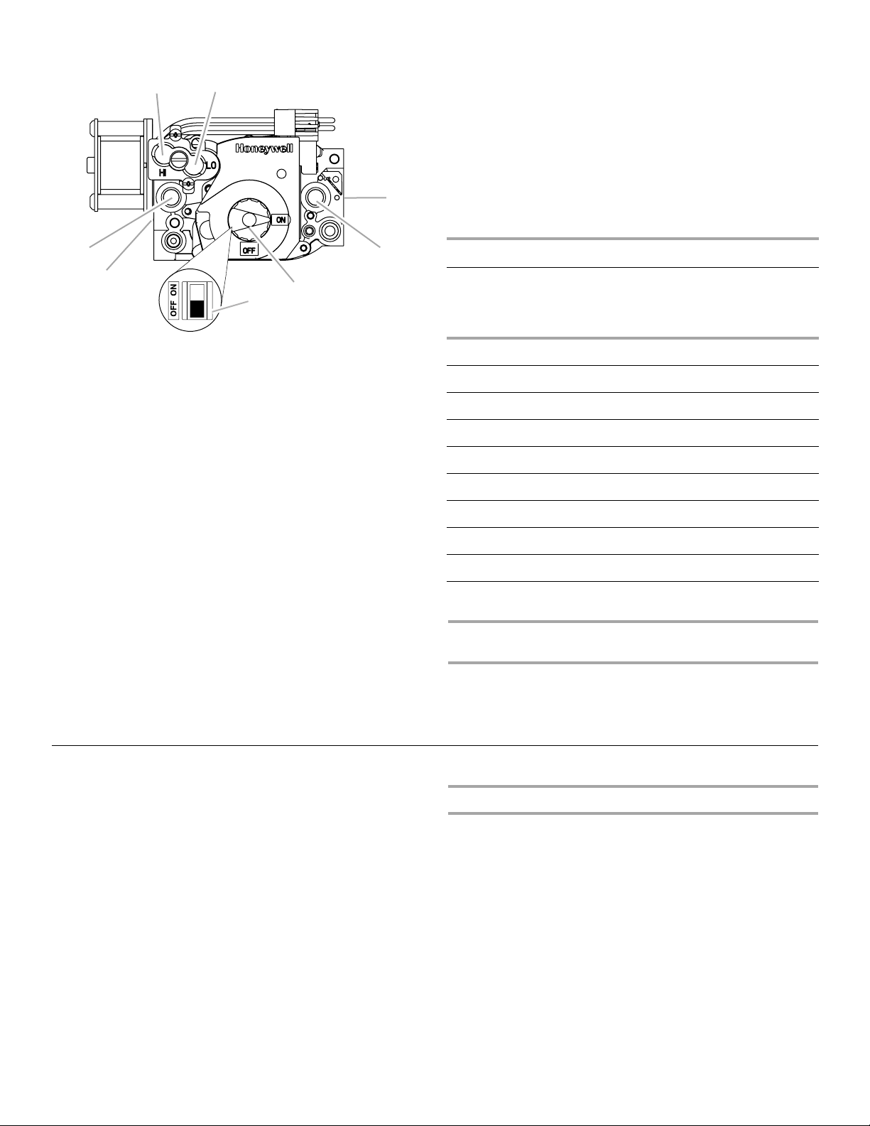
A. Regulator adjusting cap—LO
B.
¹⁄₂"
(1.3 cm) NPT outlet
¹⁄₈
" (3.2 mm) NPT outlet
C.
pressure tap (OUT P)
D. Gas control
4. Be sure the gas control has been in the OFF position for at
least 5 minutes before starting the furnace.
5. Move the gas control to the ON position.
NOTE: This furnace is equipped with an ignition device which
automatically lights the burner. This furnace cannot be lighted
manually. Do not try to light the burner by hand.
6. Turn on the electrical power to the furnace.
7. Set the room thermostat to a point above room temperature
to light the main burners.
8. Observe the pressure reading on the pressure gauge.
9. Refer to the Manifold Pressure vs. Altitude Chart later in this
section for the correct manifold pressure. If necessary, turn
the regulator adjusting screw clockwise to increase pressure
and input, or counterclockwise to decrease pressure and
input. The gas control valve has 2 separate adjusting screws
for first-stage marked “LO” and the second-stage marked
“HI.”
NOTE: The pressure regulator adjustment is sensitive; one
turn of the adjusting screw will result in a large change in
manifold pressure.
E. Alternate gas control
¹⁄₂
F.
G.
¹⁄₈
(IN P)
H. Regulator adjusting cap—HI
D
" (1.3 cm) NPT inlet
" (3.2 mm) NPT inlet pressure tap
Manifold Pressure vs. Altitude Chart for Natural Gas
Heating
Value
Altitude—ft (m)
2,000 (609.6) 948 3.5 (8.89) 1.7 (4.32)
3,000 (914.4) 914 3.5 (8.89) 1.7 (4.32)
4,000 (1,219.2) 881 3.5 (8.89) 1.7 (4.32)
4,500 (1,371.6) 865 3.5 (8.89) 1.7 (4.32)
5,000 (1,524) 849 3.29 (8.36) 1.61 (4.09)
5,500 (1,676.4) 833 3.27 (8.31) 1.6 (4.06)
6,000 (1,828.8) 818 3.25 (8.25) 1.59 (4.04)
6,500 (1,981.2) 802 3.23 (8.2) 1.58 (4.01)
7,000 (2,133.6) 787 3.21 (8.15) 1.57 (3.99)
7,500 (2,286) 771 3.19 (8.1) 1.56 (3.96)
(Btu/ft
Pressure
High Fire—
3
)
in. (cm) W.C.
Manifold
Manifold
Pressure
Low Fire—
in. (cm) W.C.
For Altitudes 7,500 to 10,000 ft (2,286 m to 3,048 m)
Above Sea Level
Do not adjust manifold pressure. An orifice change is required.
For the correct orifice size, see Table F.4 in Appendix F of the
National Fuel Gas Code (ANSI Z223.1/NFPA 54, latest edition).
Complete Installation
IMPORTANT: Do not use this furnace if any part has been under
water. Immediately call a qualified person to inspect the furnace
and to replace any part of the control system and gas control
which has been under water.
1. Check that you have all of your tools.
2. Dispose of/recycle all packaging materials.
3. Check the furnace in its final location. Be sure the vent is not
blocked.
18
Measure Temperature Rise
1. Adjust room thermostat to the highest temperature setting
possible.
2. After 20 minutes of heating operation, measure the furnace
temperature rise. Take air temperature readings in both the
return air ducts and the heated air ducts (about 72" [1.8 m]
from the furnace where they will not be affected by radiant
heat) as shown.
Page 19
NOTE: If more than one run of return or heated air ducts are
used, air temperature measurements should be taken in each
duct. These measurements can be converted to an average
to obtain the temperature rise of the whole system.
B
C
A
D
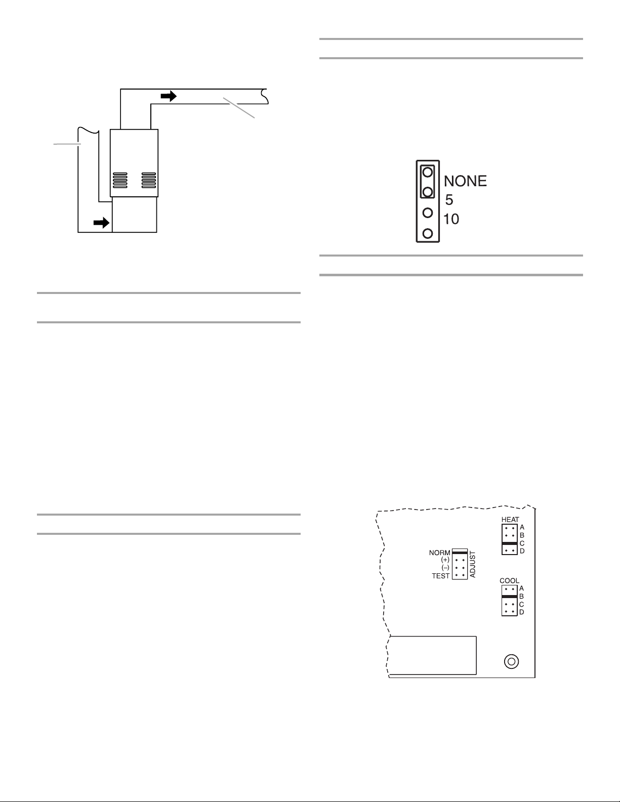
Single Stage Thermostat Operation
The automatic heat staging option allows a single stage
thermostat to be used with a two-stage furnace. To activate this
option, move the jumper pin to desired setting (5 minutes or
10 minutes). The furnace will start on 1
s
stage heat for the duration of the selected time before
at 1
switching to 2
nd
stage heat.
W1 on the control board must be connected to W1 on the
thermostat.
st
stage heat and stay
A. Measure return air here.
B. Warm air
C. Measure supply temperature here.
D. Return air
3. If furnace doesn't maintain temperature rise within the range
shown on the furnace rating plate, adjust the blower speed.
Passive and Active Dehumidification
(Variable Speed Models Only)
For situations in which condensation is a problem, a
dehumidification feature has been built into the variable speed
motor. At the start of each cooling cycle, the variable speed
motor will run at 82 percent of the rated airflow for 7¹⁄₂ minutes.
After 7¹⁄₂ minutes has elapsed, the motor will increase to
100 percent of the rated airflow. If this feature is not desired, clip
the jumper wire between R and O on the integrated ignition/
blower control board. With R and O not connected by the jumper
wire, the variable speed motor will reach 100 percent of the rated
airflow within 10 seconds of a call for cooling.
Additional dehumidification can be achieved by connecting a
humidistat to the DEHUM and R terminals on the integrated
ignition/blower control board. In this setup, the variable speed
motor will operate at a 10 percent reduction in the normal cooling
airflow rate when there is a call for dehumidification.
Both the passive and active dehumidification methods described
above can be utilized on the same furnace.
Variable Speed Features
Circulating Airflow Adjustments (Variable Speed Models)
Cooling Mode
The furnaces are factory set for the highest airflow for each
model. Adjustments can be made to the cooling airflow by
repositioning the jumper plug marked COOL—A, B, C, D based
on the information found in the Application Table For Cooling
Airflow Adjustments. To determine what CFM the motor is
delivering at any time, count the number of times the amber LED
on the control board flashes. Each flash signifies 100 CFM; count
the flashes and multiply by 100 to determine the actual CFM
delivered (for example: 10 flashes x 100 = 1,000 CFM).
Heating Mode
The furnace as shipped is factory set to run at the middle of the
heating rise range as shown on the unit rating plate. If higher or
lower rise is desired, change the rise 15 percent up or down by
moving the ADJUST jumper plug from NORM position to the (+)
or (-) position. This adjustment will also cause the cooling airflow
to be raised or lowered by 15 percent.
The TEST position on the ADJUST tap is not used.
Control Board Taps
The furnace is equipped with a variable speed circulation air
blower motor that will deliver a constant airflow within a wide
range of external static pressures. Other features of this variable
speed motor include:
Start
The variable speed motor will slowly ramp up to normal operating
speed. This minimizes noise and increases comfort by
eliminating the initial blasts of air encountered with standard
motors.
Stop
At the end of a cooling or heating cycle, the variable speed motor
will slowly ramp down after a short blower “off” delay. If
continuous blower operation has been selected, the variable
speed motor will slowly ramp down until it reaches the airflow for
that mode.
19
Page 20
Application Table for Cooling Airflow Adjustment
Heating CFM @ .5 Static Cooling CFM @ .5 Static
Model #* Motor HP ADJUST Setting HEAT Setting High Fire Low Fire A B C D
50V12 ¹⁄₃ NORM A 750 600 1,200 1,000 800 600
75V14 ¹⁄₂ NORM A 1,000 750 1,400 1,200 1,000 800
100V14 ¹⁄₂ NORM C 1,200 900 1,400 1,200 1,000 800
100V20 ³⁄₄ NORM A 1,150 700 2,000 1,800 1,600 1,400
125V20 ³⁄₄ NORM B 1,600 950 2,000 1,800 1,600 1,400
150V20 ³⁄₄ NORM C 1,450 850 2,000 1,800 1,600 1,400
For heating airflow adjustments (all models): Moving the ADJUST tap from NORM to (+) will increase airflow by 10 percent. Moving the
ADJUST tap from NORM to (-) will decrease the airflow by 12 percent.
*Only the portion of the model number (#) that indicates furnace input is shown.
Adjust Blower Speed (Multi-Speed Motor Only)
2. Place the two unused motor speed wires on the Park 1 and
WARNING
Park 2 taps.
B
C
D
Electrical Shock Hazard
Disconnect power before servicing.
Replace all parts and panels before operating.
Failure to do so can result in death or electrical shock.
NOTE: See the wiring connection diagrams in “Troubleshooting.”
■ There are three modes of blower operation: Lo Heat, Hi Heat
and Cooling. The furnace is shipped with factory settings for
each speed.
■ There are five motor speeds selectable by five different
colored wires routed from the motor to the control.
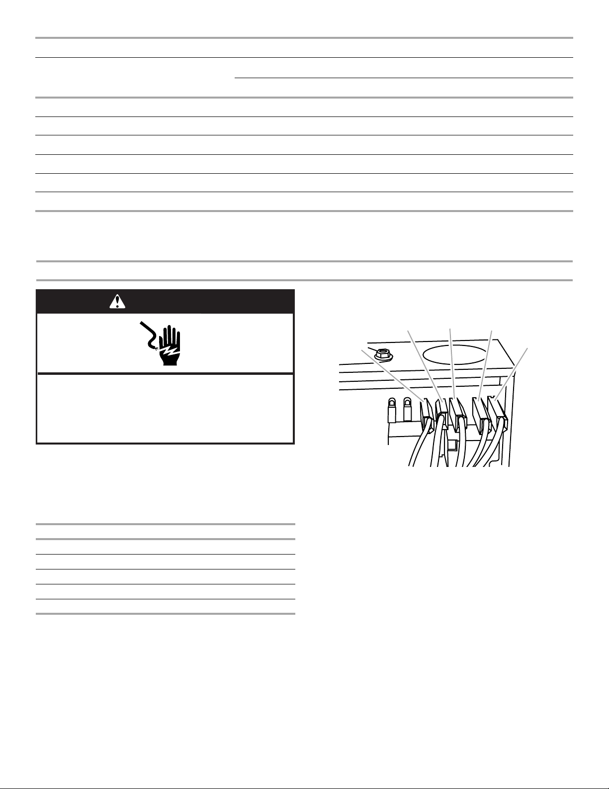
Wire Color Motor Speed
Red Low
Blue Medium
Black High
Orange Medium low
Yellow Medium high
1. Select the blower speed for each of the 3 modes by placing
the appropriate wire on the desired operation tap on the
control board.
A
A. Control board COOL tap
B. Control board Park 1 tap
C. Control board Park 2 tap
D. Control board HI HEAT tap
E. Control board LO HEAT tap
E
To Change the Blower Speed
At the control board:
1. Disconnect power.
2. Remove the blower access panel.
3. Remove the wire from the mode of operation tap to
be changed.
4. Place the appropriate colored wire on the control board tap
for the desired speed setting.
5. Place unused motor speed wire on the open PARK 1 or
PAR K 2 tap.
6. Replace the blower access panel.
7. Reconnect power.
20
Page 21
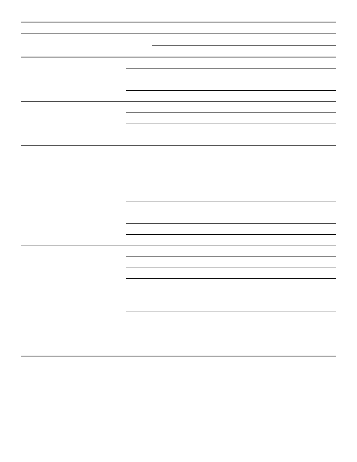
Blower Performance Data—WGFAT Models
Model
050D12B 1/3 10 x 6 30 to 60
075D14B 1/3 10 x 8 40 to 70
100D14B 1/3 10 x 8 50 to 80
100D20C 3/4 12 x 10 45 to 75
Size (hp)
Motor
Blower
Size
Rise—ºF
(ºC)
(1.1 to
15.6)
(4.4 to
21.1)
(10 to
26.7)
(7.2 to
23.9)
Te mp .
Blower
*CFM @ Ext. Static Pressure—in. w.c. with Filter(s)
Speed
Hi 1,346 1,315 1,269 1,216 1,153 1,080 995 909
Med/Hi 1,119 1,096 1,067 1,035 981 922 852 796
Med 918 905 883 843 806 767 719 644
Lo 787 764 745 713 667 639 579 523
Hi 1,653 1,600 1,542 1,476 1,395 1,309 1,232 1,107
Med/Hi 1,355 1,335 1,306 1,268 1,206 1,156 1,060 992
Med 1,078 1,061 1,051 1,032 999 963 899 680
Lo 917 910 886 869 833 795 671 582
Hi 1,658 1,609 1,538 1,474 1,413 1,337 1,243 1,107
Med/Hi 1,394 1,360 1,325 1,282 1,227 1,163 1,036 959
Med 1,104 1,101 1,077 1,047 1,009 969 903 830
Lo 931 925 904 880 843 793 645 571
Hi 2,161 2,134 2,098 2,042 2,003 1,943 1,859 1,787
Med/Hi 1,791 1,767 1,744 1,722 1,684 1,647 1,592 1,523
0.2 0.3 0.4 0.5 0.6 0.7 0.8 0.9
Med 1,558 1,525 1,514 1,495 1,455 1,412 1,376 1,321
Med/Lo 1,284 1,260 1,243 1,208 1,183 1,150 1,102 1,068
Lo 1,004 970 927 892 850 809 741 686
125D20C 3/4 12 x 10 45 to 75
(7.2 to
23.9)
150D20D 3/4 12 x 10 55 to 85
(12.8 to
29.4)
*0.5 in. w.c. Max. Approved Ext. Static Pressure
Hi 2,097 2,082 2,037 1,971 1,923 1,821 1,737 1,750
Med/Hi 1,780 1,757 1,733 1,707 1,646 1,563 1,529 1,467
Med 1,569 1,529 1,521 1,486 1,434 1,395 1,351 1,237
Med/Lo 1,310 1,283 1,253 1,225 1,189 1,156 1,094 1,020
Lo 1,017 973 950 907 828 774 720 655
Hi 2,035 2,018 1,974 1,949 1,897 1,856 1,782 1,683
Med/Hi 1,694 1,684 1,663 1,635 1,590 1,540 1,482 1,417
Med 1,480 1,470 1,449 1,420 1,384 1,338 1,268 1,208
Med/Lo 1,255 1,229 1,205 1,178 1,149 1,096 1,063 1,003
Lo 987 952 920 889 830 784 734 679
21
Page 22
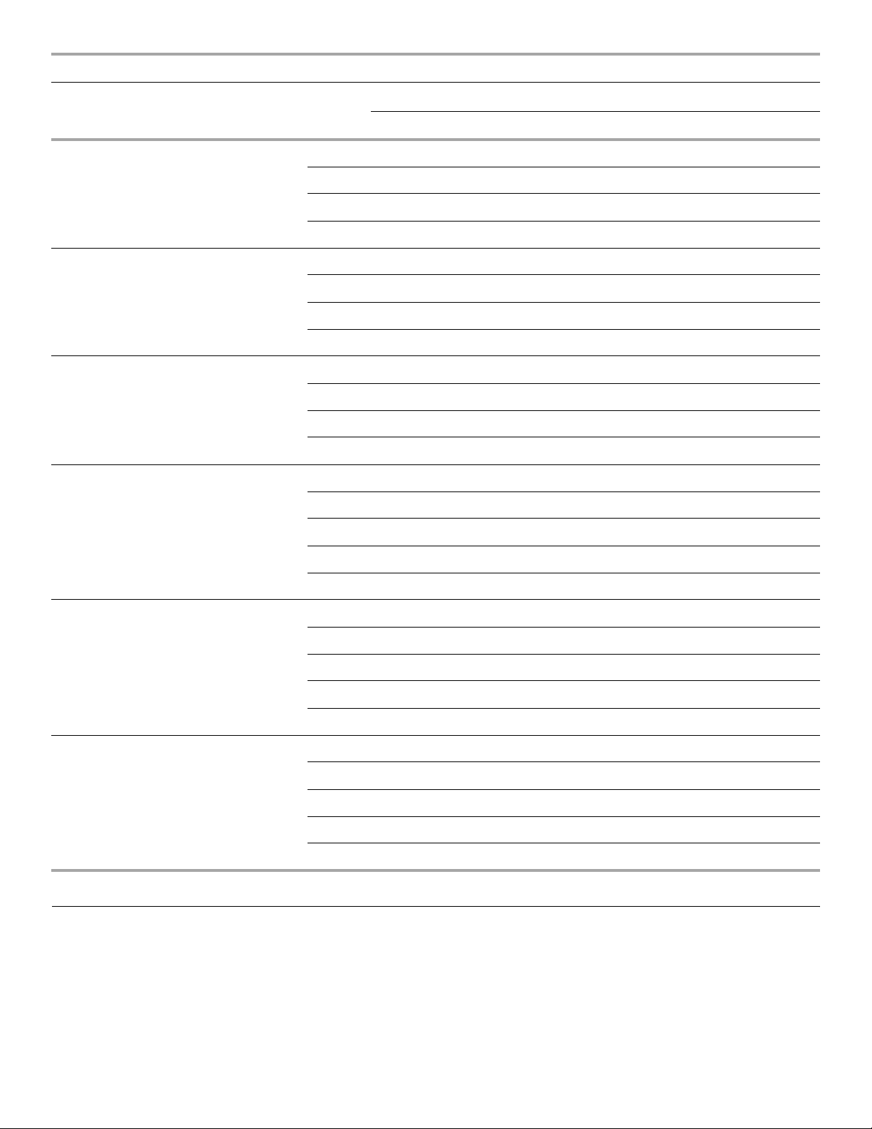
Blower Performance Data—WGFAR Models
Model
050D12 1/3 10 x 6 30 to 60
075D14B 1/3 10 x 8 40 to 70
100D14B 1/3 10 x 8 50 to 80
100D20C 3/4 12 x 10 45 to 75
Size (hp)
Motor
Blower
Size
Rise—ºF
(ºC)
(1.1 to
15.6)
(4.4 to
21.1)
(10 to
26.7)
(7.2 to
23.9)
Te mp .
Blower
*CFM @ Ext. Static Pressure—in. w.c. with Filter(s)
Speed
Hi 1,379 1,349 1,301 1,238 1,186 1,111 1,043 971
Med/Hi 1,118 1,106 1,080 1,058 1,025 971 918 842
Med 906 897 881 860 840 797 763 705
Lo 759 753 733 719 699 668 624 557
Hi 1,692 1,618 1,541 1,456 1,380 1,285 1,155 1,069
Med/Hi 1,454 1,420 1,365 1,296 1,230 1,154 1,078 950
Med 1,164 1,145 1,128 1,086 1,046 976 905 790
Lo 987 972 960 927 881 843 790 679
Hi 1,727 1,658 1,603 1,502 1,432 1,344 1,210 1,116
Med/Hi 1,445 1,429 1,404 1,344 1,262 1,192 1,095 997
Med 1,210 1,187 1,135 1,102 1,064 1,008 948 843
Lo 985 978 976 948 907 846 790 697
Hi 2,167 2,141 2,091 2,053 1,998 1,926 1,903 1,816
Med/Hi 1,784 1,757 1,724 1,700 1,668 1,599 1,527 1,408
0.2 0.3 0.4 0.5 0.6 0.7 0.8 0.9
Med 1,582 1,544 1,535 1,516 1,459 1,407 1,316 1,137
Med/Lo 1,324 1,303 1,275 1,231 1,197 1,134 1,027 971
Lo 1,015 997 956 907 843 786 688 652
125D20C 3/4 12 x 10 45 to 75
(7.2 to
23.9)
150D20D 3/4 12 x 10 55 to 85
(12.8 to
29.4)
*0.5 in. w.c. Max. Approved Ext. Static Pressure
Hi 2,174 2,148 2,095 2,019 1,953 1,877 1,772 1,641
Med/Hi 1,829 1,816 1,775 1,739 1,686 1,615 1,547 1,388
Med 1,618 1,601 1,563 1,524 1,520 1,400 1,320 1,115
Med/Lo 1,338 1,314 1,290 1,256 1,212 1,139 1,022 963
Lo 1,029 996 961 908 870 800 743 651
Hi 2,092 2,082 2,057 2,020 1,975 1,913 1,835 1,762
Med/Hi 1,772 1,756 1,732 1,704 1,661 1,622 1,555 1,485
Med 1,550 1,538 1,522 1,496 1,461 1,413 1,364 1,292
Med/Lo 1,326 1,304 1,286 1,244 1,215 1,162 1,041 979
Lo 1,038 1,000 969 905 854 812 757 682
Shut Down
If the construction will continue or the furnace will not be used for
a period of time, follow the shut down procedure.
1. Set the thermostat control(s) to the lowest setting.
2. Disconnect power.
3. Remove burner access panel.
4. Turn off the gas supply at the manual gas shutoff valve.
5. Replace the burner access panel.
22
Page 23

SEQUENCE OF OPERATION
Heating
On a call for 1st stage heat (W1) from the room thermostat, the
ignition control performs a 1-second self-check. Upon
confirmation that the pressure switch contacts are in an open
condition, the ignition control energizes the combustion blower to
high speed. The control then checks for adequate combustion air
by making sure the low-fire pressure switch contacts are closed.
The igniter energizes and is allowed to warm up for 7 seconds
before the gas control valve energizes on 1
burners ignite. The control drops the combustion blower to
low speed 45 seconds after the control confirms ignition
has occurred.
The circulating blower ramps up to 50 percent of 1
speed for 1 minute (including ramp up time), then at 75 percent of
st
stage heat speed for an additional minute. After that, the
1
circulating blower operates at full 1st stage heat speed until either
the heat call is satisfied or the thermostat initiates a call for 2
stage heat. On a call for 2
circulating air blower on full CFM 2
If the automatic heat staging option is being used, the furnace
does not switch to 2
nd
stage heat, the control energizes the
nd
stage heat in response to a call from the
nd
thermostat, but instead operates at 1st stage heat for the
duration of the selected time before automatically switching to
nd
stage heat.
2
st
If 1
stage heating operation is not sufficient to satisfy the heating
demand, the room thermostat initiates a call for 2
(W1 and W2). The control energizes the combustion blower to
high speed and energizes the W1 and W2. When the high-fire
pressure switch contacts close, the gas control valve energizes
nd
stage and the circulating blower ramps up to 2nd stage
on 2
heat speed.
st
stage and main
stage heat.
st
stage heat
nd
stage heat
nd
(VARIABLE SPEED MODELS)
nd
When the 2
closes the gas control valve and runs the combustion blower for
an additional 15 seconds. The circulating air blower continues to
run for approximately 120 seconds at 82 percent of the selected
heating speed, then ramps down to the off mode.
In the event the furnace loses ignition, the control will attempt to
recycle up to 5 times before it goes into a 1-hour lockout.
Lockout may be manually reset by removing power from the
control for more than 1 second or removing the thermostat call
for heat for more than 3 seconds.
If during a heating cycle the limit control senses an abnormally
high temperature and opens, the ignition control de-energizes the
gas control valve and the combustion blower while the circulating
blower ramps up to 2
remains energized until the limits are closed.
A call for fan from the thermostat closes R to G on the control
board. The control waits for a 1-second thermostat debounce
delay before responding by energizing the circulating blower at
50 percent of the cooling speed. When the call for fan is turned
off, the control de-energizes the circulating blower.
A call for cooling from the thermostat closes R to Y and R to G on
the integrated ignition/blower control board. The control waits for
a 1-second thermostat debounce delay before energizing the
circulating blower to 82 percent of the cooling speed. After
7¹⁄₂ minutes, the circulating blower automatically ramps up to
100 percent of the cooling speed. When the call for cooling is
satisfied, the circulating blower ramps back down to 82 percent
of the cooling speed for 60 seconds, then turns off.
stage call for heat is satisfied, the ignition control
nd
stage heat speed. The circulating blower
Fan On
Cooling
23
Page 24

SEQUENCE OF OPERATION
Heating
When the control is in standby mode, it continually monitors
thermostat input, rollout switch, and flame sense.
On a call for 1st stage heat, W1 and R are connected. The control
verifies the limit switch is closed and both low pressure and high
pressure switches are open. The control always starts on low-fire
and ignores 2
The induced draft blower is energized on high speed and waits
for the low pressure switch to close. The inducer remains on high
speed and begins a pre-purge period when the low pressure
switch closes. After a 15-second pre-purge, the control energizes
the hot surface igniter for a period of 7 seconds (15 seconds on
retries) before the gas control valve is energized on 1
burners ignite. After a 30-second blower “on” delay, the control
energizes the low heat circulating air blower. The combustion air
blower switches to low speed 15 seconds after the circulating air
blower energizes and runs at that speed until the thermostat
is satisfied.
If the 1
room thermostat initiates call for the 2
W2). The control energizes the combustion blower on high speed
and confirms the high-fire pressure switch contacts are closed. If
the contacts are closed, the gas control valve energizes on the
nd
stage and the high-heat circulating air blower is energized.
2
If the automatic heat staging option is being used, the furnace
does not switch to 2nd stage heat in response to a call from the
thermostat but instead operates at 1
of the selected time before automatically switching to 2nd stage
heat.
When the 2
control valve and runs the combustion blower for a post-purge
period of 15 seconds. The circulating air blower continues to run
until the selected blower “off” delay time (factory shipped at
120 seconds) ends.
nd
stage call for 30 seconds.
st
stage and
st
stage is not sufficient to satisfy the heating demand, the
nd
stage heat is satisfied, the control closes the gas
nd
stage heating (W1 and
st
stage heat for the duration
(MULTI-SPEED MODELS)
In the event the furnace loses ignition, the control will attempt to
recycle up to 5 times before it goes into a 1-hour lockout.
Lockout may be manually reset by removing power from the
control for more than 1 second or removing the thermostat call
for heat fo rmore than 3 seconds.
If during a heating cycle, the limit control senses an abnormally
high temperature and opens, the circulating air blower is
energized on high speed and continues to run while the limit is
still open.
Fan On
A call for fan from the thermostat closes R to G on the control
board. The control waits for a 1-second thermostat debounce
delay before responding by energizing the low heat speed blower.
When the call for fan is turned off, the control de-energizes
the blower.
Cooling
During a call for cooling, the thermostat energizes the R-Y circuit
of the control board. After a 1-second cooling “on” delay, the
control energizes the cooling fan speed. If the fan is already
energized, it remains running and does not de-energize for the
1-second cooling fan “on” delay.
The call for cooling has priority over continuous fan operation
while a call for heating has priority over both a call for cooling or
continuous fan. Ignition lockouts for any reason do not affect
cooling operation.
As cooling demand is met, the thermostat de-energizes the R-Y
circuit of the control board. After a 60-second cooling “off” delay,
the control de-energizes the cooling speed fan. At the end of the
cooling “off” delay period, the control returns to the standby
mode.
24
Page 25
CONTROLS
Following is a description of the operation of some of the controls used in this furnace. All models use one of each control, except as
noted.
Pressure Switch(s)
The pressure switch is a normally open switch that monitors
combustion airflow. Inadequate airflow resulting from excessive
venting system restriction or a failed combustion blower will
cause the switch to remain open.
Rollout Switch
The rollout switch is a normally closed switch that opens when
abnormal temperatures exist in the burner area. This can be
caused by a restricted heat exchanger, causing main burner
flame to “roll out” into the vestibule area or burner box.
These furnaces have 2 rollout switches.
Primary Limit Control
This is a normally closed control that opens if abnormally high
circulating air temperatures occur. It is an automatic reset control.
Auxiliary Limit Control
This is a normally closed control that opens under abnormal
“reverse airflow” conditions that could occur in a counterflow or
horizontal installation if the circulating blower fails. It is an
automatic reset control.
Safety Interlock Switch
Ignition Control Board
WARNING
Electrical Shock Hazard
Disconnect power before servicing.
Replace all parts and panels before operating.
Failure to do so can result in death or electrical shock.
The ignition control board operates the gas control valve,
circulating air blower, combustion blower and any accessories
connected to it. The ignition control contains control logic to
sense proper operating conditions and provides ignition only
when all conditions are properly met.
Gas Control Valve
The gas control valve regulates the manifold gas pressure and
provides gas flow.
When the blower door is removed, the safety interlock switch
breaks the power supply to the burner controls and blower motor.
25
Page 26
TROUBLESHOOTING
Furnace Fails to Operate Properly
Review “Sequence of Operation” and visually inspect the
following before troubleshooting:
WARNING
Electrical Shock Hazard
Disconnect power before servicing.
Replace all parts and panels before operating.
Failure to do so can result in death or electrical shock.
■ Is the integrated ignition/blower control board and power to
the furnace on?
■ Is the blower compartment door securely closed?
■ Are the manual shutoff valves in the gas line to the furnace
open?
■ Are all wiring connections secure?
Start the system by setting thermostat above room temperature.
Observe system response. Then use the information provided in
this section to check the system operation.
Fault Code History Button
CFM LED
On these models, an amber LED is provided on the control board
to display CFM. To determine what CFM the motor is delivering at
any time, count the number of times the amber LED flashes. Each
flash signifies 100 CFM; count the flashes and multiply by 100 to
determine the actual CFM delivered (for example: 10 flashes x
100 = 1,000 CFM).
Failure Codes
The furnace has a built-in, self-diagnostic capability. If a system
problem occurs, a fault code is shown by a red LED on the
control board. The control continuously monitors its own
operation and the operation of the system. If a failure occurs, the
LED will indicate the failure code.
IMPORTANT: Do not remove the blower compartment door or
turn off the power to the furnace because either action will clear
the control’s memory of the failure.
1. Start the system by setting the thermostat above the room
temperature.
2. Observe the system’s response.
3. Use the information provided in this section to check the
system’s operation.
Failure Codes Chart
LED Status Fault Description
LED Off No power to control or control hardware fault
detected
LED On Normal operation
The control stores the last 5 fault codes in memory. A pushbutton switch is located on the control. When the push-button
switch is pressed and released, the control flashes the stored
fault codes. The most recent fault code is flashed first; the oldest
fault code is flashed last. To clear the fault code history, press
and hold the push-button switch for more than 5 seconds before
releasing.
High Heat State LED
On these models, a green LED is provided on the control board to
indicate high heat state.
High Heat State—Green LED
LED Status Description
LED Off No demand for high heat
LED On High heat demand, operating normally
LED Flashing High heat demand, high pressure switch not
closed
1 flash Flame present with gas control valve off
2 flashes Pressure switch closed with inducer off
3 flashes Low-fire pressure, rollout, drain pressure, or
auxiliary limit open
4 flashes High limit switch open
5 flashes Not used
6 flashes Pressure switch cycle lockout
7 flashes Lockout due to no ignition
8 flashes Lockout due to too many flame dropouts
9 flashes Incorrect polarity and phasing
26
Page 27
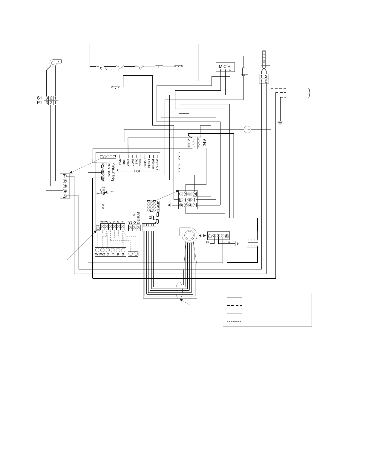
Wiring Connection Diagram—Variable Speed Models
Induced
Draft
Blower
WRBK
Pressure
High
Pressure
Switch
Switch
(Drain)
(if used)
BR V V V
Main
BR
Limit
R
Low
Pressure
Switch
W / BK
BR
BK
BK / W
Rollout
Switch
(if used)
R
Rollout
Switch
V
R / BK
OR
BU
GY
W
Gas
Control
Valve
Hot Surface
Flame
Sensor
Interlock
Switch
Igniter
2-Pin
Connector
Hot
Neutral
Ground
W
BKYY
G
120/1/60
WRBK
Connector
Fault Code
History Button
See Note 1
W
Ignition Control
Automatic
Heat Staging
Jumper5-Pin
Green LED
Red LED
Amber LED
Thermostat Condenser
W / BK
BR
GY
VV
Circulation
W
Y
Y
W
Transformer
Aux Limit
Switch
(if used)
Aux Limit
Switch
Y
Blower
BR
Typ
R
R / BKORBU
W
5-Pin
Connector
W
Input Choke
(if used)
BK
Line Voltage - Factory
Line Voltage - Field
Low Voltage - Factory
Low Voltage - Field
Check codes for proper wiring and circuit protection before
installation.
NOTES:
1. Press and release fault code history button to display fault
codes. To erase codes, press and hold button in for more
than 5 seconds.
2. If any of the original wire as supplied with the furnace must be
replaced, it must be replaced with wiring material having a
temperature rating of at least 194ºF (90ºC).
3. Proper polarity must be observed for field line voltage supply;
ignition control will lock out if polarity is reversed.
4. For temporary service replacement of circulating blower
motor with a PSC motor, connect desired speed tap to EAC
terminal and neutral tap to neutral terminal on ignition control.
5. Do not connect C (common) between the thermostat and the
furnace unless required by the thermostat manufacturer.
Refer to the thermostat installation instructions.
27
Page 28
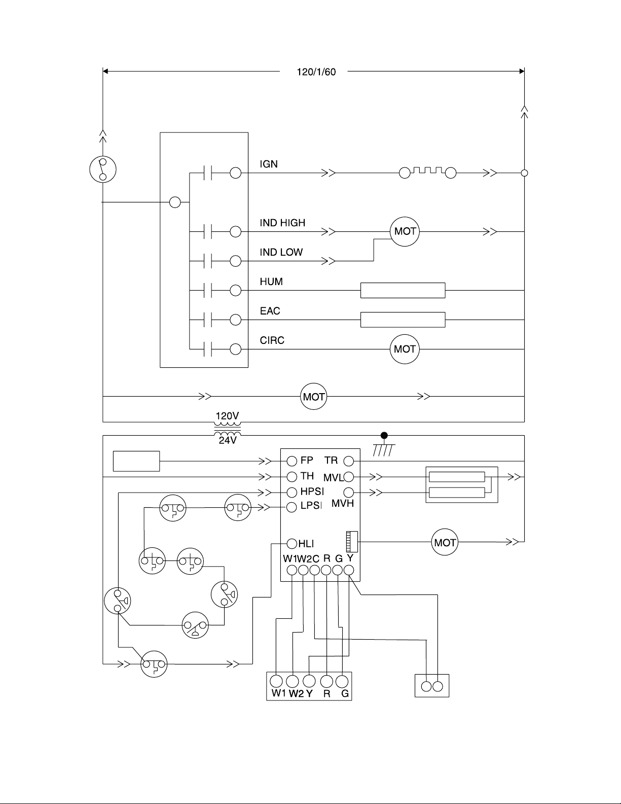
Wiring Schematic
Hot
Hot Surface
Igniter
Interlock
Switch
Induced Draft
Blower
Humidifier
Air Cleaner
Flame
Sensor
Rollout
Switch
High
Pressure
Switch
Main Limit
Aux Limit
(if used)
Rollout
Switch
(if used)
Pressure
Switch (Drain)
Aux
Limit
Low
Pressure
Switch
Transformer
Ignition
Control
Circulation
Blower
Pins
to Motor
st
1
Stage
nd
Stage
2
Gas Control Valve
28
Thermostat
Condenser
Page 29
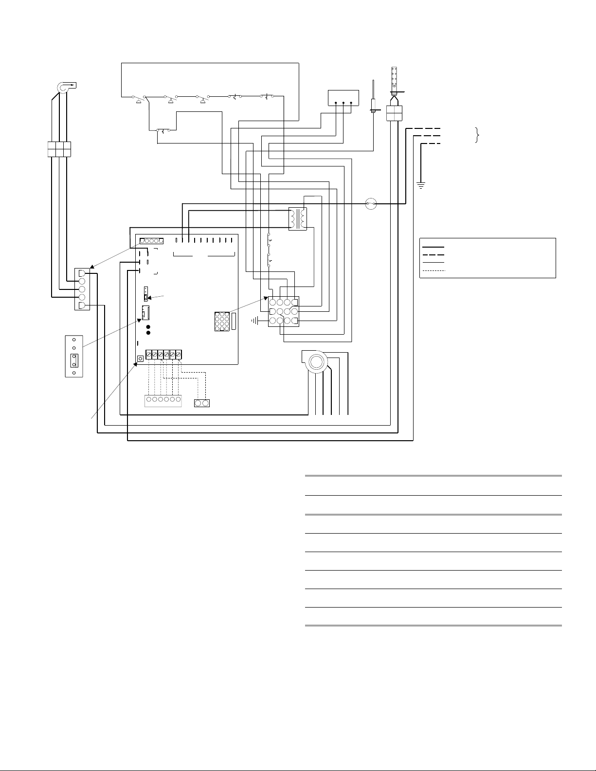
Wiring Connection Diagram—Multi-Speed Models
S1
P1
Induced
Draft
Blower
BK
R
W
3
2
1
3
2
1
WRBK
Connector
1
2
3
4
5
5-Pin
High
Pressure
Switch
EAC
CIRC
LINE
10
5
NONE
60
90
120
180
Low
Pressure
Switch
BR
Main
BR
Limit
XFMR
HUM
Neutral
P5
Automatic
Heat Staging
Jumper
P4
R
Pressure
Switch
(Drain)
(if used)
VVV
W / BK
BR
BK
BK / W
W
HUM
EAC
XFMR
COOL
LINE
CONT
PARK 1
Hot
Ignition Control
Rollout
Switch
(if used)
PARK 2
HI HEAT
LO HEAT
5 AMP
GY
R
BR
Rollout
Switch
Transformer
Aux Limit
Switch
V
(if used)
V
12
W / BK
11
10
R / BK
OR
BU
GY
V
120V
Aux Limit
Switch
9
3
6
2
8
5
41
7
Gas
Control
Valve
Flame
Sensor
Hot Surface
Igniter
CHIM
2-Pin
Connector
2211
Hot
Neutral
Ground
YYBK
W
G
W
24V
Interlock
Switch
120/1/60
See
Note 3
Line Voltage - Factory
Line Voltage - Field
Low Voltage - Factory
Low Voltage - Field
BU
OR
R / BK
R
W
Y
60
90
120
180
SW1
W1
TWIN
R
G
Y
W2
C
Circulation
Blower
Blower Off
Delay Timing
W1
W2
GRY
C
Fault Code
History Button
See Note 1
Thermostat Condenser
W
Y
Y
W
Check codes for proper wiring and circuit protection before
installation.
NOTES:
1. Press and release fault code history button to display fault
codes. To erase codes, press and hold button in for more
than 5 seconds.
2. If any of the original wire as supplied with the furnace must be
replaced, it must be replaced with wiring material having a
temperature rating of at least 194ºF (90ºC).
3. Proper polarity must be observed for field line voltage supply;
ignition control will lock out if polarity is reversed.
4. Do not connect C (common) between the thermostat and the
furnace unless required by the thermostat manufacturer.
Refer to the thermostat installation instructions.
BU (MED)
Y (MED/HI)
W (NEUT)
R (LO)
BK (HI)
OR (MED/LO)
See Blower Speed Chart
Blower Speed Chart
Model Cooling 2
50D12 BK BU R
75D14 BK BU R
100D14 BK Y R
100D20* BK BU OR
125D20* BK BU OR
150D20* BK Y OR
nd
Stage Heat 1st Stage Heat
*5-speed motor used on these models
29
Page 30
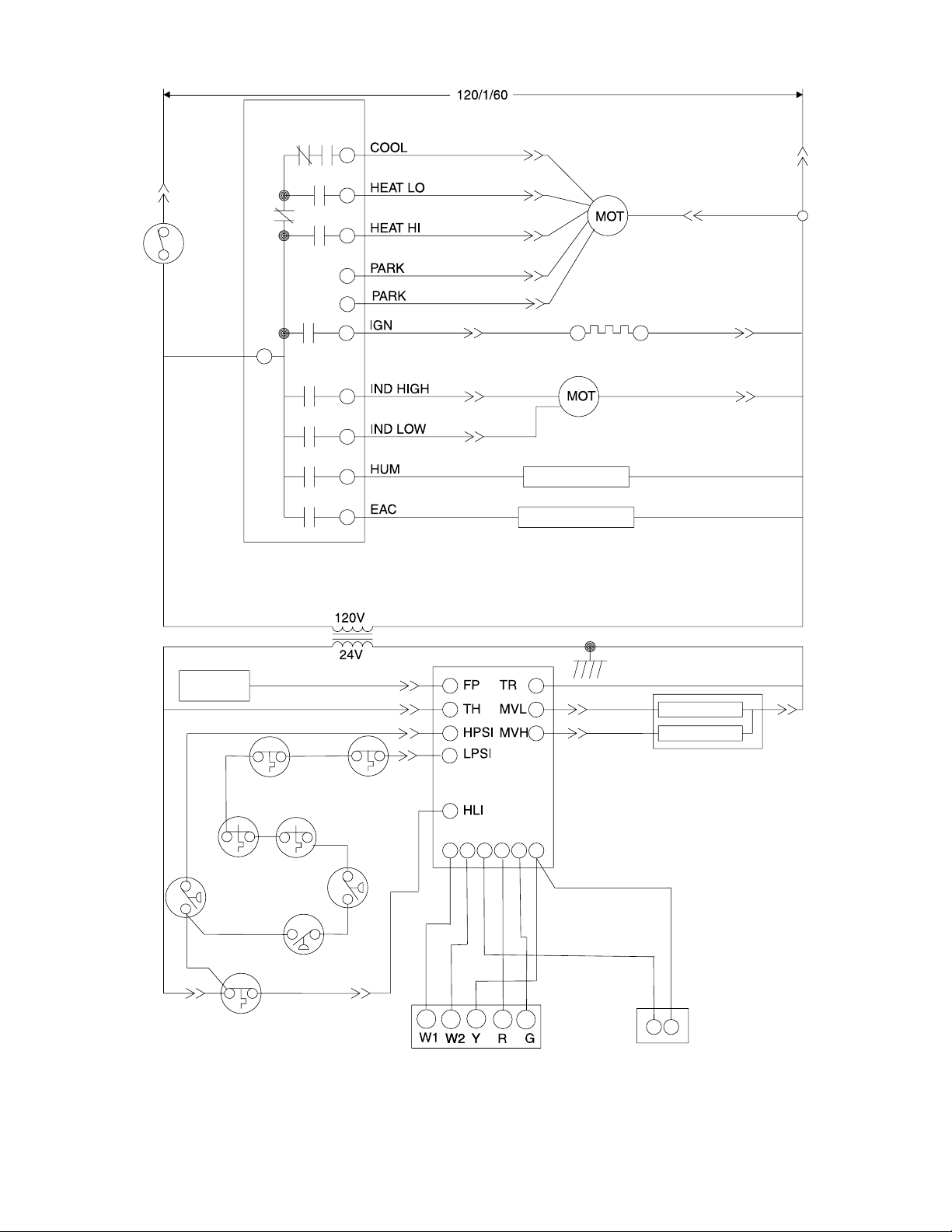
Wiring Schematic
Hot
Interlock
Switch
Ignition
Control
Neutral
Neutral
Igniter
Induced Draft Blower
Humidifier
Flame
Sensor
Aux Limit
(if used)
Rollout
Switch
High Pressure
Switch
Rollout
Switch
(if used)
Low Pressure
Switch
Aux Limit
Pressure
Switch
(drain)
Transformer
W1W2 C R G Y
Ignition
Control
Air Cleaner
st
1
Stage
nd
2
Stage
Gas Control Valve
30
Main Limit
Thermostat
Condenser
Page 31

ASSISTANCE OR SERVICE
If you need further assistance, you can write to the below
address with any questions or concerns:
Whirlpool® Home Cooling and Heating
14610 Breakers Drive
Jacksonville, FL 32258
Please include a daytime phone number in your correspondence.
Accessories
To order accessories ask for the appropriate part number listed
below or contact your Whirlpool
dealer.
ALPKT582-1 Natural Gas to Propane Conversion Kit
AFILT524-1 Side Return Filter Kit
AFILT529-2 Bottom Return Filter Kit
WABASE511 Combustible Floor Base (14¹⁄₂" [36.9 cm] cabinets)
WABASE512 Combustible Floor Base (17¹⁄₂" [44.4 cm] cabinets)
WABASE568 Combustible Floor Base (21" [53.4 cm] cabinets)
WABASE569 Combustible Floor Base (24¹⁄₂" [62.3 cm] cabinets)
ACVK2-1 Concentric Vent Kit
®
Home Cooling and Heating
31
Page 32

47724B008
©
2008. All rights reserved.
Manufactured under license by Tradewinds Distributing Company, LLC., Coconut Grove, Florida
®Registered Trademark/TM Trademark of Whirlpool, U.S.A.,
Printed in U.S.A.
3/08
 Loading...