

Whirlpool WGD8600YW0 Parts Diagram
FOR SERVICE TECHNICIAN’S USE ONLY
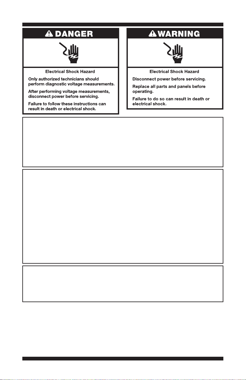
Voltage Measurement Safety Information
When performing live voltage measurements, you must do the following:
Verify the controls are in the off position so that the appliance does not start when energized.
Allow enough space to perform the voltage measurements without obstructions.
Keep other people a safe distance away from the appliance to prevent potential injury.
Always use the proper testing equipment.
After voltage measurements, always disconnect power before servicing.
IMPORTANT: Electrostatic Discharge (ESD) Sensitive Electronics
ESD problems are present everywhere. Most people begin to feel an ESD discharge at
approximately 3000V. It takes as little as 10V to destroy, damage, or weaken the main control
assembly. The new main control assembly may appear to work well after repair is finished,
but a malfunction may occur at a later date due to ESD stress.
Use an anti-static wrist strap. Connect wrist strap to green ground connection point or
unpainted metal in the appliance
-OR Touch your finger repeatedly to a green ground connection point or unpainted metal
in the appliance.
Before removing the part from its package, touch the anti-static bag to a green ground
connection point or unpainted metal in the appliance.
Avoid touching electronic parts or terminal contacts; handle electronic control assembly
by edges only.
When repackaging main control assembly in anti-static bag, observe above instructions.
This service data sheet is intended for use by persons having electrical, electronic, and
mechanical experience and knowledge at a level generally considered acceptable in the
appliance repair trade. Any attempt to repair a major appliance may result in personal injury
and property damage. The manufacturer or seller cannot be responsible, nor assume any
liability for injury or damage of any kind arising from the use of this data sheet.
Contents
IMPORTANT SAFETY NOTICE — “For Technicians only”
Whirlpool Control Panel ........................................ 2
Diagnostic Guide .................................................. 3
Activating Service Diagnostic Mode ...................... 3
User Interface/Control System Test .......................4
Install Diagnostics ................................................ 5
Software Version Display ......................................6
Fault/Error Codes .............................................6, 7
PART NO. W10403269A
DO NOT REMOVE OR DESTROY
Troubleshooting Guide .......................................... 8
Troubleshooting Tests..................................... 9–21
Voltage Hex Codes Chart .................................... 21
Strip Circuits ...................................................... 22
Component Locations ........................................ 23
Specifications ....................................................23
Wiring Diagrams ..........................................24, 25
PAGE 1
FOR SERVICE TECHNICIAN’S USE ONLY
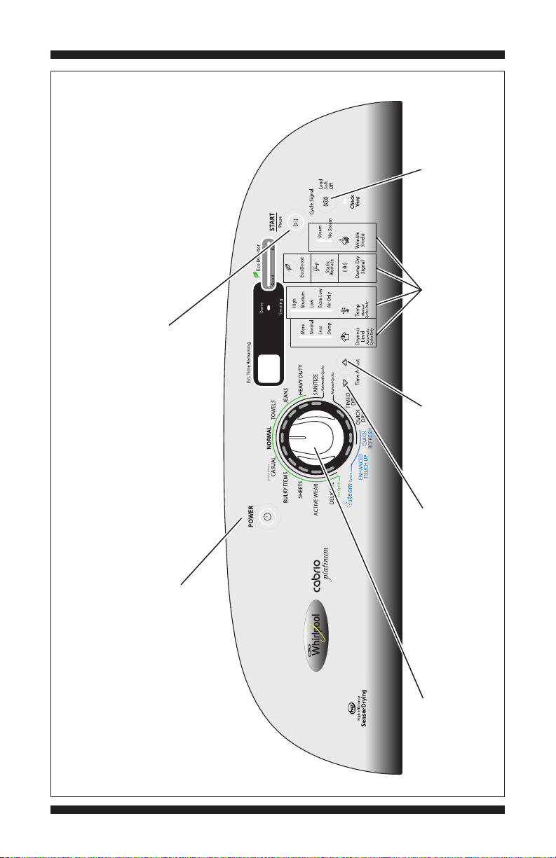
and starts motor, heater, and water valve.
START/Pause button: first press turns off LED
status LEDs.
Cycle Signal button:
press once to turn off the
EcoMonitor and Check Vent
Press each modifier
respective indicator.
button once to turn off its
to turn off left
Time Adjust (s)
segment display.
button: press once
WHIRLPOOL CONTROL PANEL (features and appearances may vary between models)
PAGE 2
POWER button: press once to turn off Done
diagnostic mode and return to standby mode.
and Sensing indicators. Press twice to exit service
to turn off right
Time Adjust (t)
segment display.
button: press once
appearances vary between models).
corresponding cycle indicator. (Features and
Rotating the cycle selector knob turns off each
DO NOT REMOVE OR DESTROY
Figure 1 - User Interface Test
FOR SERVICE TECHNICIAN’S USE ONLY
Button Press Function Behavior
1st Button- Momentary press
- Press and hold for 5 secs.
- Activates User Interface/
- Exits Service Diagnostic Mode
2nd Button- Momentary press
- Press and hold for 5 secs.
- Activates Install Diagnostics
- Software Version Display
3rd Button- Momentary press
- Press and hold for 5 secs.
- Displays Next Error Code
- Clears the Error Codes
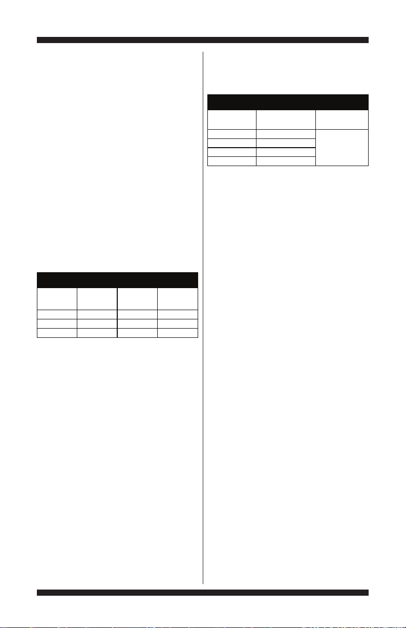
SERVICE DIAGNOSTIC MENU TABLE
Control System Test
DIAGNOSTIC GUIDE
Before servicing, check the following:
Make sure there is power at the wall outlet.
Has a household fuse blown or circuit breaker
tripped? Was a regular fuse used? Inform
customer that a time-delay fuse is required.
Is dryer vent properly installed and clear
of lint or obstructions?
All tests/checks should be made with a
VOM (volt-ohm-milliammeter) or DVM
(digital-voltmeter) having a sensitivity of
20,000 Ω per volt DC or greater.
Resistance checks must be made with
dryer unplugged or power disconnected.
IMPORTANT: Avoid using large
diameter probes when checking harness
connectors as the probes may damage
the connectors upon insertion.
Check all harnesses and connections
before replacing components. Look for
connectors not fully seated, broken or
loose wires and terminals, pin insertion,
or wires not pressed into connectors
far enough to engage metal barbs.
A potential cause of a control not
functioning is corrosion or contamination on
connections. Using an ohmmeter, check for
continuity across suspected connections.
SERVICE DIAGNOSTIC MODE
These tests allow service personnel to test
and verify all inputs to the machine control
electronics. You may want to do a quick and
overall checkup of the dryer with these tests
before going to specific troubleshooting tests.
ACTIVATING SERVICE DIAGNOSTIC MODE
1. Be sure the dryer is in standby mode
(plugged in with all indicators off).
2. Select any three buttons (except POWER)
and follow the steps below, using the same
buttons. Remember the buttons and the order
that the buttons were pressed.
Within 8 seconds,
• Press and Release the 1st selected button,
• Press and Release the 2nd selected button,
• Press and Release the 3rd selected button;
• Repeat this 3 button sequence 2 more times.
3. If the key sequence was entered
successfully, all indicators on the console are
illuminated for 5 seconds with “88” showing
in the “estimated time remaining” two-digit
display. If there are no saved fault codes, all
indicators on the console will momentarily
turn off, and then only the seven segment
display will come back on and display “88”.
NOTE: The Service Diagnostic mode will time
out after 10 minutes of user inactivity, or shut
down if AC power is removed from the dryer.
Unsuccessful Activation
If entry into diagnostic mode is unsuccessful,
refer to the following indications and actions:
Indication 1: None of the indicators or display turn on.
Action: Select any cycle.
If indicators come on, try to change the
function for the three buttons used to activate
the diagnostic test mode. If any button is
unable to change the function, something
is faulty with the button, and it will not be
possible to enter the diagnostic mode using
that button. Replace the user interface and
housing assembly.
DO NOT REMOVE OR DESTROY
PAGE 3

FOR SERVICE TECHNICIAN’S USE ONLY
If no indicators come on after selecting the
cycle, go to TEST #1: CCU Power Check,
page 9.
Indication 2: Console indicators begin flashing
immediately.
Action: If console indicators begin flashing on
and off immediately, replace the user interface.
Activation with Saved Fault Codes
If there is a saved fault code, it will be
flashing in the display. Review the Fault/Error
Codes table on page 7 for the recommended
procedure. If there is no saved fault code,
“88” will be displayed.
USER INTERFACE/
CONTROL SYSTEM TEST
NOTE: The Service Diagnostic mode must be
activated before entering the User Interface/
Control System Test; see procedure on page 3.
Active Fault Code Display
in User Interface/Control System Test
If the display begins flashing while in User
Interface/Control System Test, it is displaying
an active fault code. Active fault codes are
codes that are currently detected. Only one
active fault code can be displayed at a time.
Entry Procedure
Press and release the 1st button used
to activate Service Diagnostic mode.
The following tests will be available:
1. DIAGNOSTIC: Console Buttons
and Indicators
Pressing each button will turn off its
corresponding indicator(s) or display segment
and sound a beep as shown in Figure 1, page 2.
Rotating the cycle selector knob turns off each
corresponding cycle indicator.
NOTE: A second press of the POWER/Cancel
button while in Console Buttons and Indicators
mode exits the Service Diagnostic mode and
returns the dryer to standby mode.
If indicators do not turn off and beep
after pressing buttons and rotating the cycle
selector knob, go to TEST #6: Buttons and
Indicators, page 19.
2. DIAGNOSTIC: Console ID, Motor,
Heater, and Water Valve (if exists)
Make sure the door is closed, and then press
the START button. The dryer will beep and the
motor, heater, and water valve (if exists) will
turn on. One of the following console IDs will
be displayed on the LED by alternating the first
two and last two digits (82-00, 84-00, 86-00,
or 88-00). Opening the door stops the motor,
heater, and water valve.
If the Console ID is not displayed, replace
the user interface and housing assembly.
If the motor does not turn on, go to TEST
#3: Motor Circuit, page 12.
If no heat is detected, go to TEST #4:
Heat System, page 13.
If no water is detected, go to TEST #9:
Water Valve, page 20.
3. DIAGNOSTIC: Door Switch/Drum Light
Opening the door should display “7e” (electric)
or “79” (gas) and turn on the drum light.
Closing the door should turn off the drum light.
If opening the door does not cause “7e”
(electric) or “79” (gas) to be displayed,
go to TEST #7: Door Switch, page 20.
If opening the door does not turn on the
drum light, go to TEST #8: Drum Light,
page 20.
4. DIAGNOSTIC: Moisture Sensor
Open the door and locate two metal strips
on the face of the lint screen housing. Bridge
these strips with a wet cloth or a finger.
If a repeating beep is heard and an
alphanumeric number is displayed
on the console, the sensor is good.
If not, or if a beep tone is heard before
bridging the moisture strips, go to
TEST #5: Moisture Sensor, page 18.
Exit Procedure
To exit User Interface/Control System Test,
press the POWER button once or twice
(depending on diagnostic procedure).
PAGE 4
DO NOT REMOVE OR DESTROY
FOR SERVICE TECHNICIAN’S USE ONLY
STEP TEST TEST DRYER FUNCTION COMPONENT NOTES
1 Dryer starts L2 detection.
Motor On Display shows “- - -” until voltage is
available at UI.
2 L2 detection complete.
Motor On
• If Electric: Display of L2 level, in Hex
(see Voltage Hex Code chart, page 21).
• If Gas: Display of “9s” for gas since L2
does not exist.
3
Dryer starts L1 detection.
Airflow detection routine begins.
Motor On
Heater On
Hex value (see chart, page 21) or “9s”
(if gas dryer) continues to display on L ED.
4
L1 detection complete.
CCU calculates L1 + L2.
Motor On
Heater On/Off
Once L1 is calculated, L1 + L2 is
immediately calculated in the CCU.
5
Press the START button to cycle
through L1, L2, and L1 + L2.
Motor On
Heater On/Off
• Display of L1 : in Hex value (see char t,
page 21).
• Display of L2: in H ex value (see chart ,
page 21) or “9s” (if gas dry er).
• Display of L1 + L2: in Hex value
(see chart, page 21). L1 + L2 =
240 V AC ± 10%, or “9s” if gas dryer.
6 Airflow test near completion.
Motor On
Heater On/Off
The display will count d own the final 15
seconds of t he AirFlow detection routine.
7
Airflow detection complete.
Motor Off
Heater Off
When the airflow routine is complete,
the Dryness Level modifier LED will
light up showing Airflow result: More
LED (Good), Less LED (Bad), or no
LED (Invalid). In addition, the seven
segment display will show airflow
result (0=BAD, 1=GOOD, 2=INVALID).
8
START/Pause button begins to flash.
Press the START/Pause button to
begin water system test.
Water Valve On
-s on display.
9
Steam test running. Water turns on. Water Valve On
Water is actuated for 30 seconds and
then test completes.
INSTALL DIAGNOSTICS
L
1
L
2
&
L
1
t
o
L
2
D
E
T
E
C
T
A
I
R
F
L
O
W
W
A
T
E
R
Heater Off
Heater Off
INSTALL DIAGNOSTICS
NOTE: The Service Diagnostic mode must be
activated before entering Install Diagnostics;
see procedure on page 3.
NOTE: If, at any point, the user presses the
power button or opens the door during Install
Diagnostics, the dryer exits to standby mode.
Active Fault Code Display
in Install Diagnostics
If the display begins flashing while in Install
Diagnostics, it is displaying an active fault
code. Active fault codes are codes that are
currently detected. Only one active fault code
can be displayed at a time.
Entry Procedure
To enter Install Diagnostics, press and release
the 2nd button used to activate the Service
Diagnostic mode. All LEDs turn off and the
START/Pause button begins to flash.
WATER-ONLY TEST: Press and hold the
START/Pause button for at least 5 seconds
to run only the water system test.
PERFORM ALL TESTS: Press and release the
START/Pause button to run the tests indicated
in the chart below.
Exit Procedure
When test is complete, press and hold the 1st button
used to activate the Service Diagnostic mode for
5 seconds to exit Install Diagnostics. Opening and
closing the door will also exit the test mode.
* Dryer performance is optimized for 2-phase, 240 V AC ser vice. If complaint is made regarding dryer performance and the L1 to L2 voltage
is ~208 V AC, dryer may be connected to a 3-phase service with reduced wattage that will decrease dryer per formance. Also check the
Customer-Focused Dryness Level setting (see page 19).
DO NOT REMOVE OR DESTROY
PAGE 5

FOR SERVICE TECHNICIAN’S USE ONLY
CODE DESCRIPTION EXPLANATION AND RECOMMENDED PROCEDURE
PF Power Failure
PF indicates that a power failure occurred while the dryer was running.
Press START to continue the cycle, or press POWER to clear the display.
L2 Low Line Voltage
L2 indicates low L2 voltage (less than 50 V) is detected at installation.
• Refer to Fault/Error Code “F4E4”, page 7, for recommended procedure.
CUSTOMER FAULT/ERROR CODES
SOFTWARE VERSION DISPLAY
NOTE: The Service Diagnostic mode must be
activated before entering the Software Version
Display mode. The Software Version Display
mode will time out after 10 minutes of user
inactivity and return to standby mode.
Entry Procedure
To enter Software Version Display, press and
hold the 2nd button used to activate the Service
Diagnostic mode for at least 5 seconds.
• CCU software revision code (C: major
revision number, C: minor revision number,
C: test revision number) will alternate on
the display.
Exit Procedure
Press and hold the 1st button used to activate
the Service Diagnostic mode for 5 seconds
or press the POWER button to exit Software
Version Display and return dryer to standby
mode.
FAULT/ERROR CODES
Refer to fault/error code chart on page 7.
Fault/Error Code Display Method
Fault codes are displayed by alternately
showing F# and E#. All fault codes have an
F# and an E#. The F# indicates the suspect
System/Category. The E# indicates the
suspect Component system.
Up to four Fault/Error codes may be stored.
When the oldest fault code is displayed,
additional presses of the 3rd button will result
in a triple beep, then display of the most recent
fault code. If each press of the 3rd button
results in a triple beep and the display shows
“88”, no saved fault codes are present.
Advancing Through Saved Fault/
Error Codes
Procedure for advancing through saved
fault codes:
Press and release g beep tone g most recent fault
the 3rd button code is displayed.
used to activate
Service Diagnostics
Repeat g beep tone g second most
recent fault code
is displayed.
Repeat g beep tone g third most
recent fault code
is displayed.
Repeat g beep tone g fourth most
recent fault code
is displayed.
Repeat g triple beep g back to the most
recent fault code.
Clearing Fault Codes
To clear stored fault codes, enter Service
Diagnostic mode. Then press and hold the
3rd button used to enter Service Diagnostic
mode for at least 5 seconds. Once the stored
fault codes are successfully erased, the
seven segment display will show “88”.
EXITING SERVICE DIAGNOSTIC MODE
Use either of the two methods below to exit
diagnostic mode.
• Pressing and holding the 1st button
used to activate the Service Diagnostic
mode for 5 seconds.
• Pressing the POWER button once or twice,
depending on diagnostic procedure.
PAGE 6
DO NOT REMOVE OR DESTROY
FOR SERVICE TECHNICIAN’S USE ONLY
CODE DESCRIPTION EXPLANATION AND RECOMMENDED PROCEDURE
F1E1
Cycle Control Unit
(CCU) Problem
Indicates a CCU problem.
• Verify all connections to and from the CCU.
• See TEST #1: CCU Power Check, page 9.
.
F2E1
User Interface (UI)
Problem (stuck button)
Indicates a stuck button (depressed for over 20 seconds) or UI
mismatch. This fault code will ONLY appear when in the service
diagnostic mode. See TEST #6: Buttons and Indicators, page 19.
.
F2E2
User Interface
Appears if UI cannot read EEPROM software from UI.
• Verify all connections between CCU and UI.
• Replace the UI.
F3E1
Exhaust Thermistor
Open
Indicates that the exhaust thermistor is open. Temperature drops
below 18° F (> 50k ohms). See TEST #4a: Thermistors, page 16.
F3E2
Exhaust Thermistor
Shorted
Indicates that the exhaust thermistor has shorted. Temperature
above 250° F (< 500 ohms). See TEST #4a: Thermistors, page 16.
F3E3
Inlet Thermistor Indicates that the Inlet Thermistor is open. Temperature drops
below 18° F (> 245k ohms). See TEST #4a: Thermistors, page 16.
F3E4
Inlet Thermistor Indicates that the Inlet Thermistor is shorted. Temperature above
391° F (< 20 ohms). See TEST #4a: Thermistors, page 16.
F3E5
Inlet and Exhaust
Thermistors Open
Indicates that the Inlet and Exhaust Thermistors are open.
Will occur if the P14 connector is not plugged into the CCU.
F3E6
Moisture Sensor
Open
Indicates the moisture sensor strip is open. This fault code will
only appear when in the service diagnostic mode. See TEST #5:
Moisture Sensor, page 18.
.
F3E7
Moisture Sensor
Shorted
Indicates that the moisture sensor strip has shorted. This fault
code will ONLY appear when in the service diagnostic mode.
See TEST #5: Moisture Sensor, page 17.
.
F4E1
Heater Relay or
Connector Problem
Indicates no voltage detected at the heater relay. This fault code
will ONLY appear when in the service diagnostic mode.
• Unplug dryer or disconnect power and check that the wires are
plugged into the heater element(s) and the relay(s) on the CCU.
F4E3 Restricted Air Flow
Indicates low air flow that may affect dryer performance.
• Confirm that airflow system is not blocked, check lint screen,
exhaust duct, exhaust fan.
.
F4E4 L2 Line Voltage
Error
L2 indicates low L2 voltage (less than 50 V) is detected
at installation.
• Check to see if a household fuse has blown or a circuit breaker
• Confirm the power cord is properly installed and plugged
• Check the relay connections on the CCU.
• Gas Models Only: Check the P14 connection on the CCU.
SERVICE FAULT/ERROR CODES
Software Error 1
Open
Shorted
has tripped.
into the power outlet.
(Harness loopback on Pins 4 & 5)
DO NOT REMOVE OR DESTROY
PAGE 7
FOR SERVICE TECHNICIAN’S USE ONLY
PROBLEMPOSSIBLE CAUSE CHECKS & TESTS
No power to dryer. Check power at outlet, check circuit breaker,
fuses, or junction box connections.
Connection problem between AC plug and dryer.See Test #2: Supply Connections, page 10.
Connection problem between CCU and UI.Check connections and harness continuity
between CCU and UI.
Power supplies not present at machine electronics. See Test #1: CCU Power Check, page 9.
User Interface problem. See Test #6: Buttons & Indicators, page 19.
Door not fully closed or striking the door latch.Be sure the door is completely closed,
then press and hold the START button.
Door Switch problem. See Test #7: Door Switch, page 20.
Drive Belt / Belt Switch problem. See Test #3: Motor Circuit, page 12.
Thermal Fuse / Motor problem. See Test #3: Motor Circuit, page 12.
User Interface problem. See Test #6: Buttons & Indicators, page 19.
CCU problem. See Test #1: CCU Power Check, page 9.
Poor airflow.Check lint screen and exhaust vent. Clean
if necessary.
Check the START/Pause button. Perform UI Component Test under
Component Activation.
Moisture Sensor problem. See Test #5: Moisture Sensor, page 18.
Thermistor problem. See Test #4a: Thermistors, page 16.
User Interface problem. See Test #6: Buttons & Indicators, page 19.
CCU problem. See Test #1: CCU Power Check, page 9.
User selects invalid option. Refer customer to “Use and Care Guide”.
User Interface problem. See Test #6: Buttons & Indicators, page 19.
Drive Belt / Belt Switch problem. See Test #3: Motor Circuit, page 12.
Thermal Fuse (electric only). See Test #4b: Thermal Fuse, page 17.
Door switch problem. See Test #7: Door Switch, page 20.
Motor problem. See Test #3: Motor Circuit, page 12.
CCU problem. See Test #1: CCU Power Check, page 9.
Check installation. Verify proper dryer installation.
Check for L1 and L2. Perform CCU L1 and L2 tests under Install
Diagnostics.
Heater system malfunction or open heater coil. See Test #4: Heat System, page 13.
CCU problem. See Test #1: CCU Power Check, page 9.
Heater coil shorted. See Test #4: Heat System, page 13.
Heater relay shorted. See Test #4: Heat System, page 13.
Heater system problem. See Test #4: Heat System, page 13.
Dryness setting for auto cycles.Increase drying times for one or more
Lint screen full. Clean if necessary. Refer customer
to “Use and Care Guide”.
Heater vent clogged. Clean if necessary. Refer customer
to “Use and Care Guide”.
Moisture Sensor problem. See Test #5: Moisture Sensor, page 18.
Adjust Customer Focused Dryness Level. See Test #5a: Adj. Cust. Focused
Dryness Check, page 19.
Steam cycle not selected. Refer customer to “Use and Care Guide”.
No water to valve. Verify water supply is turned on.
No water from valve. See Test #9: Water Valve, page 20.
WATER VALVE NOT DISPENSING
(
Water valve is activated intermittently
during the steam cycle.)
WILL NOT HEAT
HEATS IN AIR CYCLE
SHUTS OFF BEFORE CLOTHES
ARE DRY
DRUM WILL NOT SPIN
CONSOLE WON’T ACCEPT
SELECTIONS
WILL NOT POWER UP
- No operation
- No keypad response
- No LED's or display
WILL NOT START CYCLE
(No response when START/Pause
button is pressed.)
WILL NOT SHUT OFF
WHEN EXPECTED
auto cycles.
TROUBLESHOOTING GUIDE
PAGE 8
DO NOT REMOVE OR DESTROY
FOR SERVICE TECHNICIAN’S USE ONLY
TROUBLESHOOTING TESTS
IMPORTANT: The following procedures
may require the use of needle probes
to measure voltage. Failure to use needle
probes will damage the connectors.
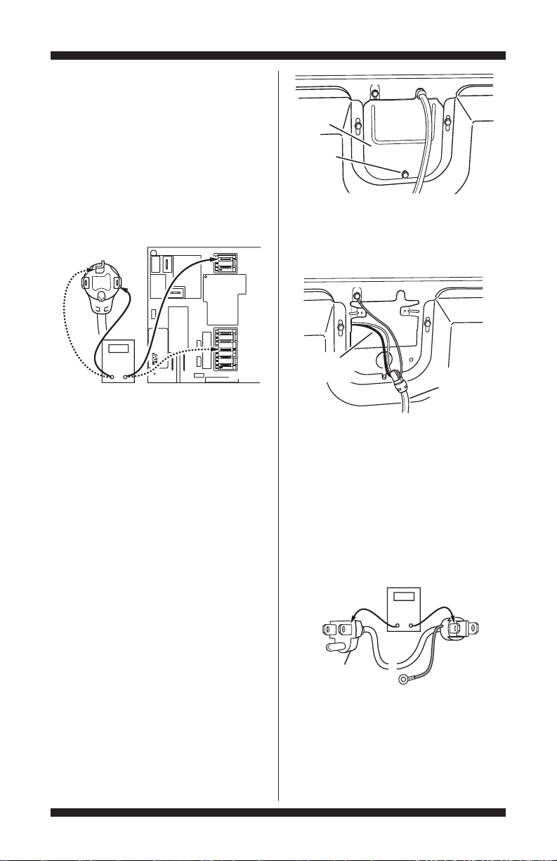
TEST #1: CCU Power Check
This test checks for incoming and outgoing power
to and from the Cycle Control Unit (CCU). This test
assumes that proper voltage is present at the outlet.
1. Unplug dryer or disconnect power.
2. Check for appropriate line voltages at the
outlet: 240V AC (electric 2-phase), 208V AC
(electric 3-phase), or 120V AC (gas).
If line voltage is present, go to step 3.
If line voltage is not present, check for
tripped circuit breaker or blown household
fuse. If CB (circuit breaker) is not tripped,
have customer check with qualified
electrician.
3. Remove console to access the CCU
and User Interface (UI).
4. Plug in dryer or reconnect power.
P2 – +5 V DC
P2-1 +5V DC
P2-2
P2-3 5V GND
P8 – WATER VALVE/DOOR SWITCH
P8-4 TAN DOOR SWITCH
P8-3 WHT NEUTRAL
P8-2 G/Y CHASSIS GND
P8-1 RED WATER VALVE
Heater Relay #1
L1 – BLK (N.O.)
(Gas & Elect.)
P5 – USER INTERFACE
P5-1 +5V DC
P5-2 DATA IN
P5-3 GND
P5-4 STROBE
P5-5 DATA OUT
P5-6 CLOCK
P5-7 BUZZER
P14-3 R/W OUTLET THERMISTOR
P14-2 RED INLET THERMISTOR
P14-1 RED INLET THERMISTOR
P5-8 +12V DC
P9
5. CCU AC – With voltmeter set to AC,
connect black probe to CCU P8-3 (N) and
red probe to P9-2 (L1). (See Figure 2.)
If 120V AC is present, go to step 6.
If 120V AC is not present, perform TEST
#2: Supply Connections, page 10.
6. CCU +5V DC – Perform the following
voltage checks inside header P2—DO NOT
SHORT PINS TOGETHER. With voltmeter
set to DC, connect black probe to CCU P2-3
(ground) and red probe to P2-1 (+5V DC).
If +5V DC is present, go to step 9.
If +5V DC is not present, go to step 7.
7. Unplug dryer or disconnect power.
Unplug P14 from the CCU. Plug in dryer
or reconnect power and repeat step 6.
If +5V DC returns, one of the thermistors
has shorted. To diagnose thermistors,
see TEST #4a, page 16.
If +5V DC is not present, go to step 8.
8. Unplug dryer or disconnect power.
Reconnect P14 to the CCU and unplug P5
from the CCU. Plug in dryer or reconnect
power and repeat step 6.
P9 – MOTOR/L1
P9-2 BLK L1
P9-1 LT BLU MOTOR
P13 – MOISTURE SENSOR
P13-2 Y/R MOISTURE SENSOR
P13-1 Y/R MOISTURE SENSOR
P14 – THERMISTORS
P14-6 R/W OUTLET THERMISTOR
P14-5 BLK MODEL RTN (GAS MODEL)
P14-4 BLK MODEL (GAS MODEL)
Motor Relay
P13
Heater (E) – VLT (COM)
Heater (G) – RED (COM)
Heater Relay #2
(Elect. Only)
L1 – BLK (N.O.)
Heater (E) – VLT (COM)
K2
K3
Figure 2 - CCU Connectors & Pinouts
DO NOT REMOVE OR DESTROY
K1
P8
P14
P5
P2
t
= pin-1
PAGE 9
FOR SERVICE TECHNICIAN’S USE ONLY
COM
N
L1
If +5V DC is still missing, replace the CCU.
If +5V DC returns, check harness and
connections between the CCU and User
Interface (UI). If acceptable, replace the UI.
9. CCU +12V DC – with voltmeter set to DC,
connect black probe to CCU P5-3 (ground)
and red probe to P5-8 (+12V DC).
If +12V DC is present, go to step 11.
If +12V DC is not present, go to step 10.
10. Unplug dryer or disconnect power. Unplug
P5 from the CCU. Plug in dryer or reconnect
power and repeat step 9 by performing the
voltage check inside header P5—DO NOT
SHORT PINS TOGETHER.
If +12V DC is still missing, replace the CCU.
If +12V DC returns, check harness and
connections between the CCU and User
Interface (UI). If acceptable, replace the UI.
11. Unplug dryer or disconnect power.
12. Reassemble all parts and panels.
13. Perform steps under “Install Diagnostics”,
page 5, to verify repair.
TEST #2: Supply Connections
This test assumes that proper voltage is
present at the outlet, and for U.S. installations,
a visual inspection indicates that the power
cord is securely fastened to the terminal block
(electric dryer) or wire harness connection
(gas dryer).
ELECTRIC DRYER (U.S. Installations):
1. Unplug dryer or disconnect power.
2. Remove the cover plate from the back
of the dryer. See Figure 3.
Cover Plate
Figure 3 - Remove the cover plate (electric).
3. With an ohmmeter, check for continuity
between the neutral (N) terminal of the plug
and the center contact on the terminal block.
See Figure 4a.
Remove Screw
If there is no continuity, replace the power
cord and test the dryer.
If there is continuity, go to step 4.
4. In a similar way, check which terminal of
the plug is connected to the left-most contact
on the terminal block and make a note of
it. This will be L1 (black wire) in the wiring
diagram. See Figure 4a.
When this is found, go to step 5.
If neither of the plug terminals have
continuity with the left-most contact of the
terminal block, replace the power cord and
retest dryer.
Power Cord
Plug
Figure 4a - Plug-to-terminal connections
for electric dryer.
Terminal Block
5. Access the machine electronics without
disconnecting any wiring to the CCU.
6. With an ohmmeter, check for continuity
between the L1 terminal of the plug (found
in step 4) and P9-2 (black wire) on the CCU.
If there is continuity, go to step 7.
If there is no continuity, check that wires to
the terminal block are mechanically secure.
If so, replace the main wire harness and
test the dryer.
7. Check for continuity between the neutral
(N) terminal of the plug and P8-3 (white wire)
on the CCU.
If there is continuity, go to step 8.
If there is no continuity, and the mechanical
connections of the wire are secure, replace
the main wire harness.
8. Visually check that ALL connectors are
fully inserted into the CCU.
9. Visually check that ALL connectors are
fully inserted into the UI.
10. Reassemble all parts and panels.
11. Plug in dryer or reconnect power.
12. Perform steps under “Install Diagnostics”,
page 5, to verify repair.
PAGE 10
DO NOT REMOVE OR DESTROY
COM
Neu
G
L1
L1
Masse
N
Neu
N
G
Masse
P9
1
5
1
P/N XXXXXX Rev X
Date Code YDDD-xx
XXXX-XXX
MADE IN COO
L1
COM
P8
L1
N
Neu
N
Neu
FOR SERVICE TECHNICIAN’S USE ONLY
ELECTRIC DRYER (Canadian Installations):
1. Unplug dryer or disconnect power.
2. Remove the cover plate from the back
of the dryer. See Figure 3, page 10.
3. Access the machine electronics without
disconnecting any wiring to the CCU.
4. With an ohmmeter, check the continuity
from L1 and N plug terminals of the power
cord to the terminals for L1 and N on the
CCU. See Figure 4b.
Power Cord
Plug
Figure 4b - Plug-to-terminal connections
for electric dryer.
If continuity exists for both connections,
go to step 6.
If an open circuit is found, check the integrity
of the connections of the power cord to the
harness in the dryer; harness to the CCU;
and the integrity of the power cord itself.
5. If it is necessary to replace the power
cord, remove the retaining clip that secures
the cord to the back panel. Disconnect the
cord from the main harness and the ground
wire from the rear panel, then pull out the
power cord.
6. Visually check that ALL connectors are
fully inserted into the CCU.
7. Visually check that ALL connectors are
fully inserted into the UI.
8. Reassemble all parts and panels.
9. Plug in dryer or reconnect power.
10. Perform steps under “Install Diagnostics”,
page 5, to verify repair.
GAS DRYER (U.S. and Canadian Installations):
1. Unplug dryer or disconnect power.
2. Remove the cover plate from the back
of the dryer. See Figure 5.
DO NOT REMOVE OR DESTROY
CCU
Cover Plate
Remove
Screw
Figure 5 - Remove the cover plate (gas).
3. Check that the power cord is firmly
connected to the dryer’s wire harness.
See Figure 6.
Wire Harness
Power Cord
Figure 6 - Power cord-to-wire harness
connection for gas dryer.
4. Access the machine electronics without
disconnecting any wiring to the CCU.
5. With an ohmmeter, check for continuity
between the neutral (N) terminal of the plug and
P8-3 (white wire) on the CCU. The left-hand
side of Figure 7 shows the position of the neutral
terminal (N) on the power cord plug. Also see
Figure 2, page 9.
Power Cord
Plug
Figure 7 - Power cord terminals, gas dryer.
PAGE 11
FOR SERVICE TECHNICIAN’S USE ONLY
Part of Motor System
Electric
Dryer
Gas
Dryer
Drum belt
��
Door switch
��
Harness/connection
��
Thermal fuse
�
no
Drive motor
��
Belt switch
��
Centrifugal switch
��
Machine control electronics
��
If there is continuity, go to step 6.
If there is no continuity, disconnect the
white wire of the main harness from the
power cord at the location illustrated in
Figure 6. Test the continuity of the power
cord neutral wire as illustrated in Figure 7.
If an open circuit is found, replace the
power cord. Otherwise, go to step 6.
6. In a similar way, check for continuity
between the L1 terminal of the plug and P9-2
(black wire) on the CCU.
If there is continuity, go to step 8.
If there is no continuity, check the continuity
of the power cord in a similar way to that
illustrated in Figure 7, but for power cord’s
L1 wire.
If an open circuit is found, replace the power
cord. Otherwise, replace the main harness.
7. Visually check that ALL connectors are fully
inserted into the CCU.
8. Visually check that ALL connectors are fully
inserted into the UI.
9. Reassemble all parts and panels.
10. Plug in dryer or reconnect power.
11. Perform steps under “Install Diagnostics”,
page 5, to verify repair.
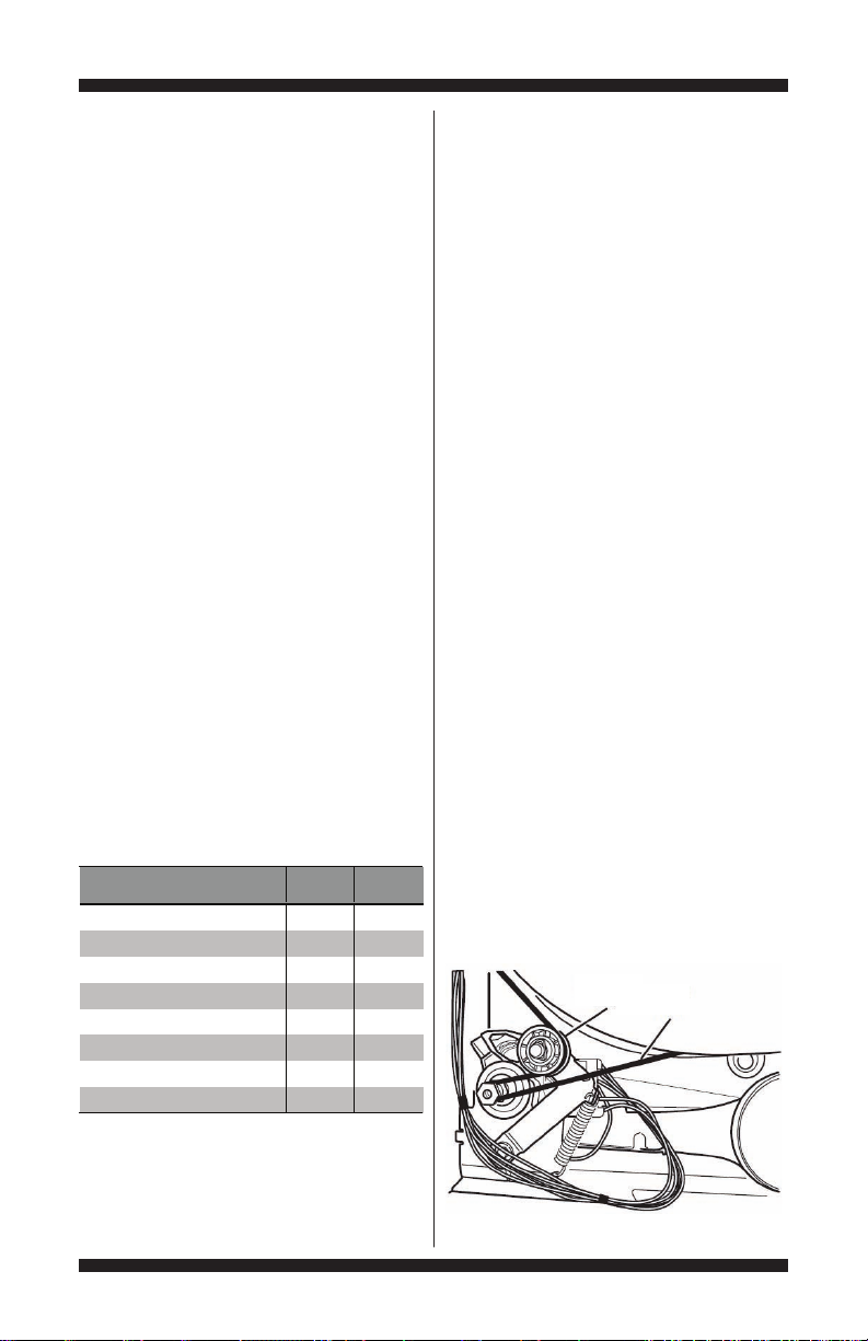
TEST #3: Motor Circuit
This test will check the wiring to the motor
and the motor itself. The following items are
part of this motor system:
1. Unplug dryer or disconnect power.
2. Remove the back panel and check for loose,
worn, or damaged drum belt—repair as necessary.
3. Remove console to access the CCU and
User Interface (UI).
4. Door Switch problems can be uncovered
by following procedure under TEST #7: Door
Switch, page 20; however, if this was not
done, the following can be performed without
applying power to the dryer. Connect an
ohmmeter across CCU P8-3 (neutral, white
wire) and P8-4 (door, tan wire).
With the door properly closed, the ohmmeter
should indicate a closed circuit (0–2 Ω).
If not, check harnesses and connections
between CCU and door switch. If good,
replace the door switch assembly.
5. Motor Circuit Check - Access the CCU and
measure the resistance across P8-4 and P9-1.
If resistance across P8-4 and P9-1 is in
the range of 1 to 6 Ω, the motor circuit is
acceptable. Replace the CCU.
Otherwise, continue to step 6.
6. Check the wiring and components in the path
between these measurement points by referring
to the appropriate wiring diagram (gas or electric)
on pages 24–25.
ELECTRIC DRYER ONLY: Check the thermal fuse.
See TEST #4b: Thermal Fuse, page 17.
ALL DRYERS: Continue with step 7 below to test
the remaining components in the motor circuit.
7. Check the drive motor and belt switch.
Slowly remove the drum belt from the springloaded belt switch pulley, gently letting the belt
switch pulley down. See Figure 8.
Belt Switch
Pulley
Drum
Belt
NOTE: Refer to Strip Circuit on page 22
to diagnose drive motor.
PAGE 12
Figure 8 - Slowly remove drum belt.
DO NOT REMOVE OR DESTROY
FOR SERVICE TECHNICIAN’S USE ONLY
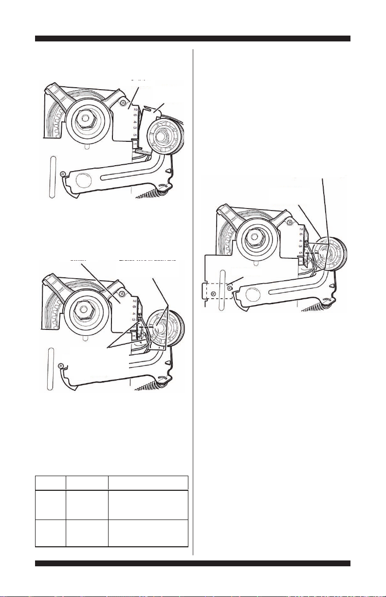
Winding
Resistance
in ohms
Contact Points
of Measurement
MAIN1.4–2.6
Lt. blue wire in back at pin 4
and bare copper wire terminal
removed from pin 5 of black
drive motor switch
START1.4–2.8
Lt. blue wire in back at pin 4
and bare copper wire terminal
on pin 3 of black drive
motor switch
8. Remove the white connector from the drive
motor switch. See Figure 9.
9. Remove the bare copper wire terminal from
pin 5 of black drive motor switch. See Figure 10.
Figure 10 - Main and start winding measure points.
10. Using Figure 10 and the Strip Circuit on
page 22, check for the resistance values of
the motor’s Main and Start winding coils as
shown in the following table.
NOTE: Main and Start winding coils must be
checked at the motor.
DO NOT REMOVE OR DESTROY
Drive Motor
Switch
Connector
Figure 9 - Remove white connector.
Drive Motor
Switch
Start Winding:
Lt. Blue Wire in Back and
Bare Copper Wire
(3 position)
Main Winding:
Lt. Blue Wire in Back
and Bare Copper Wire
(5 position)
White
If the resistance at the motor is correct,
there is an open circuit between the motor
and CCU. Go to step 11 to check for belt
switch problem.
If the Start winding resistance is much
greater or less than the values listed in the
previous table, replace the motor.
11. Check the belt switch by measuring
resistance between the two light blue wires,
as shown in Figure 11, while pushing up the
belt switch pulley.
Belt Switch
Figure 11 - Checking the belt switch.
Lt. Blue Wires
(Back and 4 Position)
Belt Switch
Tension Pulley
If the resistance reading goes from open to a
few ohms as pulley arm closes the switch, belt
switch is good. If not, replace the belt switch.
If belt switch is good and there is still an open
circuit, check and repair the main wiring harness.
12. Reassemble all parts and panels.
13. Plug in dryer or reconnect power.
14. Perform steps under “Install Diagnostics”,
page 5, to verify repair.
TEST #4: Heat System
This test is performed when one or more
of the following situations occurs:
3Dryer does not heat
3Heat will not shut off
3Display flashes L2 (electric only)
This test checks the components making up
the heating circuit. The following items are
part of this system:
PAGE 13
FOR SERVICE TECHNICIAN’S USE ONLY
Part of Heating System
Electric
Dryer
Gas
Dryer
Harness/connection
��
Heater relays
��
Thermal cut-off
��
Thermal fuse no
�
High limit thermostat
��
Heat element assemblies
�
no
Gas valve assembly no
�
Centrifugal switch
��
Outlet thermistor
��
Inlet thermistor
��
Machine control electronics
��
Console electronics and housing
assembly
��
Gas supply no
�
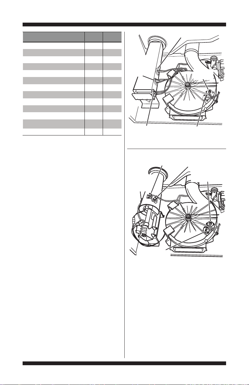
Thermal Cut-Off
Inlet
Thermistor/
High Limit
Thermostat
Outlet
Thermistor
NOTE: On the gas dryer, the inlet thermistor is
located at the top of the drum inlet vent. Refer
to Strip Circuit on page 22 to diagnose heater
system.
Dryer does not heat:
Display flashes L2 (electric only):
Locate the components using Figures 12a
and 12b.
ELECTRIC DRYER ONLY:
3Quick Check: Perform steps under “Install
Diagnostics”, page 5, to test for L1 and L2
line voltage.
•IfL1ispresent,thethermalcut-off
and heater relay #1 are functional.
•IfL2ispresent,thecentrifugalswitch,
high limit thermostat, and the side of the
heater connected to heater relay #1 are
functional.
1. Unplug dryer or disconnect power.
2. Remove console to access the CCU and
User Interface (UI). Remove front panel and
drum to access thermal components.
3. Check Heaters—on the CCU, use an
ohmmeter to measure the resistance between
the violet wire terminal on heater relay #1 and
the violet wire terminal on heater relay #2.
If the resistance is ≤50 Ω, go to step 5.
If an open circuit is detected, go to step 4.
PAGE 14
Heater Element
Figure 12a - Thermal components,
electric dryer, viewed from front.
High Limit
Thermostat
Flame
Sensor
Thermal
Fuse
Figure 12b - Thermal components,
gas dryer, viewed from front.
Thermal Fuse
Thermal Cut-Off
Outlet
Thermistor
4. Visually check the wire connections between
each relay and their respective heaters. If the
connections look good, check for continuity
across each heater (violet wire to center red
wire). Refer to Strip Circuit on page 22.
Replace the heater if it is electrically open.
5. Check Thermal Cut-off—on the CCU, use an
ohmmeter to measure continuity between P9-2
(L1) and the black wire terminal on heater relay
#1. Then, measure continuity between P9-2
(L1) and the black terminal on heater relay #2.
DO NOT REMOVE OR DESTROY

FOR SERVICE TECHNICIAN’S USE ONLY
If there is continuity, go to step 7.
If an open circuit is detected, go to step 6.
6. Visually check the wire connections between
each relay (black wire) and the thermal cut-off. If
the connections look good, check for continuity
across the thermal cut-off.
Replace the thermal cut-off if it is
electrically open.
7. Check High Limit Thermostat—visually
check the wire connections from the heaters
and centrifugal switch to the high limit
thermostat. If the connections look good, check
for continuity across the high limit thermostat.
Replace the high limit thermostat if it is
electrically open.
8. If no open circuit is detected, remove the
P14 connector from the CCU and measure the
outlet thermistor resistance between P14-3
and P14-6 at the connector. Refer to “Outlet
Thermistor Resistance” table on page 16 for
temperatures and the associated values.
If the resistance corresponds to the
temperature, the outlet thermistor is good.
Go to step 9.
If the resistance does not agree with the
table, replace the outlet thermistor.
9. If the preceding steps did not correct the
problem and L1 and L2 were both detected,
replace the CCU. If L2 was not detected, suspect
the centrifugal switch before replacing the CCU.
10. Reassemble all parts and panels.
11. Plug in dryer or reconnect power.
12. Perform steps under “Install Diagnostics”,
page 5, to verify repair.
GAS DRYER ONLY:
1. Verify the gas supply to the dryer is turned on.
2. Unplug dryer or disconnect power.
3. Perform TEST #4b: Thermal Fuse on page
17. If the thermal fuse is OK, go to step 4.
4. Perform TEST #4c: Thermal Cut-Off on page
17. If the thermal cut-off is OK, go to step 5.
5. Locate the high limit thermostat (see
Figure 12b, page 14). Measure the continuity
through it by connecting the meter probes
to the black and red wire terminals.
If there is an open circuit, replace both the
high limit thermostat and the thermal cut-off.
Otherwise, go to step 6.
6. Perform TEST #4d: Gas Valve on page
17. If the gas valve is OK, go to step 7.
7. If the preceding steps did not correct
the problem, suspect the centrifugal switch
before replacing the CCU.
8. Reassemble all parts and panels.
9. Plug in dryer or reconnect power.
10. Perform steps under “Install Diagnostics”,
page 5, to verify repair.
Heat will not shut off:
ALL DRYERS:
1. Unplug dryer or disconnect power.
2. Remove console to access the CCU
and User Interface (UI).
3. Remove connector P14 from the CCU
and measure the resistance between P14-3
and P14-6 at the connector. Refer to “Outlet
Thermistor Resistance” table on page 16 for
temperatures and the associated values.
If the resistance corresponds to the
temperature, the outlet thermistor is good.
If the thermistor resistance does not agree
with the table, replace the outlet thermistor;
if open, repair as necessary.
4. ELECTRIC DRYER ONLY: Check heater
coil(s) for a short to ground (usually inside
the heater box). Repair or replace if necessary.
5. Plug in dryer or reconnect power.
6. Run an Air Only Timed Dry cycle (no heat).
Check heater relay output(s) on CCU. With a
voltmeter set to AC, measure the voltage across
the N.O. and COM terminals for heater relay #1.
Repeat procedure with heater relay #2.
If voltage is present (~240V AC for electric,
~120V AC for gas), the relay is open and
working normally.
If little or no voltage is present, the relay is closed
and heater is activated. Replace the CCU.
7. Unplug dryer or disconnect power.
8. Reassemble all parts and panels.
9. Plug in dryer or reconnect power.
10. Perform steps under “Install Diagnostics”,
page 5, to verify repair.
DO NOT REMOVE OR DESTROY
PAGE 15
FOR SERVICE TECHNICIAN’S USE ONLY
TEMPERATURE
SETTING
HEAT TURNS OFF*
°F (°C)
HEAT TURNS ON
°F (°C)
High 155° ± 5° (68° ± 3°)
Medium 140° ± 5° (60° ± 3°)
Low 125° ± 5° (52° ± 3°)
Extra Low 105° ± 5° (41° ± 3°)
EXHAUST TEMPERATURES
10–15° (6–8°)
below the
heat turn off
temperature
TEMP.
°F (°C)
RES.
RANGE
k ohms
TEMP.
°F (°C)
RES.
RANGE
k ohms
50° (10°) 19.0–22.0 80° (27°)8.5–10.5
60° (16°) 14.8–16.8 90° (32°)6.8–8.8
70° (21°)11.5–13.5 100° (38°)5.0–7.0
OUTLET THERMISTOR RESISTANCE
TEST #4a: Thermistors
NOTE: Refer to Strip Circuit on page 22 to
diagnose outlet and inlet temperature thermistors.
Outlet (Exhaust) Thermistor
The CCU monitors the exhaust temperature
using the outlet thermistor, and cycles the
heater relay on and off to maintain the desired
temperature. NOTE: Begin with an empty dryer
and a clean lint screen.
1. Unplug dryer or disconnect power.
2. Remove console to access the CCU and
User Interface (UI).
3. Remove connector P14 from the CCU
and measure the resistance between P14-3
and P14-6 at the connector. The following
table gives temperatures and the associated
resistance values.
NOTE: All thermistor resistance measurements
must be made while dryer is unplugged and
connector removed from CCU.
If the resistance is OK, the outlet thermistor
is good. Proceed to step 4.
If the thermistor resistance does not agree
with the table, replace the outlet thermistor.
4. Check P14-3 and P14-6 to dryer cabinet
ground. If either pin indicates continuity
to ground (short), replace wiring harness;
otherwise, proceed to step 5.
5. If the preceding steps did not correct the
problem, replace the CCU.
Temperature Levels Incorrect – If no error code
is displayed and the connections to the thermistor
are good, check the exhaust temperature value
at any or all of the temperature levels in question,
using the TIMED DRY cycle.
1. Remove load from dryer and disconnect
external vent.
2. Plug in dryer or reconnect power.
3. Run a TIMED DRY cycle of at least 5
minutes in duration. Select high, medium,
low, or extra low.
PAGE 16
4. Using a calibrated temperature probe,
take a temperature measurement in the center
of the exhaust outlet. The correct exhaust
temperatures are as follows:
If the temperature is not reached within
~7 minutes, check voltage level and vent
blockage, and then retest.
If the temperature probe does not agree
with temperature setting, replace the outlet
thermistor.
If the temperature probe confirms the
temperature setting, retest at a different
temperature setting.
5. If the preceding steps did not correct the
problem, replace the CCU.
Inlet Thermistor
NOTE: On the electric dryer, the inlet thermistor
is part of the high thermostat assembly (see
Figure 12a, page 14). On the gas dryer, the
inlet thermistor is located at the top of the drum
inlet vent (see Figure 17, page 23).
The CCU monitors the inlet temperature using
the inlet thermistor. The inlet thermistor (along
with the outlet thermistor) is used to detect air
flow, and assists in calculating load size.
1. Unplug dryer or disconnect power.
2. Remove console to access the CCU and
User Interface (UI).
3. Remove connector P14 from the CCU
and measure the resistance between P14-1
and P14-2 at the connector. The following
tables (electric & gas) give temperatures
and the associated resistance values.
NOTE: All thermistor resistance measurements
must be made while dryer is unplugged and
connector removed from CCU.
If the resistance is OK, the inlet thermistor
is good. Proceed to step 4.
If the thermistor resistance does not agree
with the table, replace the inlet thermistor.
DO NOT REMOVE OR DESTROY
 Loading...