

Whirlpool WGD8500SR1, WGD8300SW2, WGD8300SE2, WGD8300SB2 Owner’s Manual
ELECTRONIC
GASDRYER
In the U.S.A., for questions about features, operation/performance,
In Canada, for assistance, installation and service call: 1-800-807-6777
or visit our website at... www.whirlpool.com or www.whirlpool.ca
parts, accessories or service call:
1-800-253-1301
P
SECHEUSEAGAZ
ELECTRONIQUE
Pour assistance, installation ou service composez le :
Table of Contents/Table des mati_res ......................... 2
1-800-807-6777
ou visitez notre site web &
www.whirlpool.ca
W10151582A

TABLEOFCONTENTS
TABLEDESMATIERES
DRYER SAFETY .............................................................................. 3
INSTALLATION INSTRUCTIONS .................................................. 4
Tools and Parts ............................................................................ 4
Optional Pedestal ......................................................................... 5
Location Requirements ............................................................... 5
Electrical Requirements ............................................................... 7
Gas Supply Requirements ........................................................... 8
Venting Requirements .................................................................. 9
Plan Vent System ....................................................................... 10
Install Vent System ..................................................................... 11
Install Leveling Legs ................................................................... 11
Make Gas Connection ............................................................... 12
Connect Vent .............................................................................. 12
Level Dryer ................................................................................. 12
Reverse Door Swing .................................................................. 13
Complete Installation ................................................................. 14
DRYER USE .................................................................................. 15
Starting Your Dryer ..................................................................... 15
Stopping or Restarting Your Dryer ............................................ 16
Lock Controls ............................................................................. 16
Drying and Cycle Tips ................................................................ 16
Status Lights .............................................................................. 16
Cycles ......................................................................................... 17
Additional Features .................................................................... 18
Changing Cycles, Options and Modifiers .................................. 18
Drying Rack Option .................................................................... 18
DRYER CARE .............................................................................. 19
Cleaning the Dryer Location ...................................................... 19
Cleaning the Lint Screen ............................................................ 19
Cleaning the Dryer Interior ......................................................... 20
Removing Accumulated Lint ...................................................... 20
Vacation and Moving Care ......................................................... 20
TROUBLESHOOTING .................................................................. 21
ASSISTANCE OR SERVICE ......................................................... 23
ACCESSORIES ............................................................................. 23
WARRANTY .................................................................................. 24
SI:!:CURITE DE LA SI:!:CHEUSE .................................................... 25
INSTRUCTIONS D'INSTALLATION ............................................. 26
Outillage et pieces ...................................................................... 26
Piedestal facultatif ...................................................................... 27
Exigences d'emplacement ........................................................ 27
Specifications electriques .......................................................... 29
Alimentation en gaz .................................................................... 30
Exigences concernant I'evacuation ........................................... 31
Planification du systeme d'evacuation ...................................... 33
Installation du systeme d'evacuation ......................................... 34
Installation des pieds de nivellement ......................................... 34
Raccordement au gaz ................................................................ 35
Raccordement du conduit d'evacuation ................................... 35
Mise a niveau de la secheuse .................................................... 35
Inversion du sens d'ouverture de la porte ................................. 35
Achever I'installation .................................................................. 37
UTILISATION DE LA SI:!:CHEUSE................................................ 38
Mise en marche de la secheuse ................................................ 38
Arr_t ou remise en marche de la secheuse ............................... 39
Verrouillage des commandes ..................................................... 39
Conseils pour le sechage et les programmes ........................... 39
Temoins lumineux ...................................................................... 40
Programmes ............................................................................... 40
Caracteristiques supplementaires ............................................. 41
Changement des programmes, options et modificateurs .........42
Option de grille de sechage ....................................................... 42
ENTRETIEN DE LA SI:!:CHEUSE................................................. 43
Nettoyage de I'emplacement de la secheuse ........................... 43
Nettoyage du filtre a charpie ...................................................... 43
Nettoyage de I'interieur de la secheuse ..................................... 44
Retrait de la charpie accumulee ................................................ 44
Precautions a prendre pour les vacances et avant un
demenagement .......................................................................... 44
DI!:PANNAGE ................................................................................. 45
ASSISTANCE OU SERVICE ......................................................... 47
ACCESSOIRES ............................................................................. 47
GARANTIE ..................................................................................... 48
DRYERSAFETY
Your safety and the safety of others are very important.
We have provided many important safety messages in this manual and on your appliance. Always read and obey all safety
messages.
This is the safety alert symbol.
This symbol alerts you to potential hazards that can kill or hurt you and others.
All safety messages will follow the safety alert symbol and either the word "DANGER" or "WARNING."
These words mean:
You can be killed or seriously injured if you don't immediately
follow instructions.
You can be killed or seriously injured if you don't follow
instructions.
All safety messages will tell you what the potential hazard is, tell you how to reduce the chance of injury, and tell you what can
happen if the instructions are not followed.
WARNING: For your safety, the information in this manual must be followed to minimize
the risk of fire or explosion, or to prevent property damage, personal injury, or death.
- Do not store or use gasoline or other flammable vapors and liquids in the vicinity of this
or any other appliance.
- WHAT TO DO IF YOU SMELL GAS:
• Do not try to light any appliance.
• Do not touch any electrical switch; do not use any phone in your building.
• Clear the room, building, or area of all occupants.
• Immediately call your gas supplier from a neighbor's phone. Follow the gas supplier's
instructions.
• If you cannot reach your gas supplier, call the fire department.
- Installation and service must be performed by a qualified installer, service agency, or
the gas supplier.
In the State of Massachusetts, the following installation instructions apply:
[] Installations and repairs must be performed by a qualified or licensed contractor, plumber, or gasfitter qualified or licensed by
the State of Massachusetts.
[] If using a ball valve, it shall be a T-handle type.
[] A flexible gas connector, when used, must not exceed 3 feet.
IMPORTANT SAFETY INSTRUCTIONS
WARNING: To reduce the risk of fire, electric shock, or injury to persons when using the dryer, follow basic precautions,
including the following:
• Read all instructions before using the dryer.
• Do not place items exposed to cooking oils in your dryer.
Items contaminated with cooking oils may contribute to
a chemical reaction that could cause a load to catch fire.
• Do not dry articles that have been previously cleaned in,
washed in, soaked in, or spotted with gasoline, dry-
cleaning solvents, or other flammable or explosive
substances as they give off vapors that could ignite or
explode.
• Do not allow children to play on or in the dryer. Close
supervision of children is necessary when the dryer is
used near children.
• Before the dryer is removed from service or discarded,
remove the door to the drying compartment.
• Do not reach into the dryer if the drum is moving.
• Do not install or store the dryer where it will be exposed
to the weather.
• Do not tamper with controls.
• Do not repair or replace any part of the dryer or attempt
any servicing unless specifically recommended in this
Use and Care Guide or in published user-repair
instructions that you understand and have the skills to
carry out.
• Do not use fabric softeners or products to eliminate static
unless recommended by the manufacturer of the fabric
softener or product.
• Do not use heat to dry articles containing foam rubber or
similarly textured rubber-like materials.
• Clean lint screen before or after each load.
• Keep area around the exhaust opening and adjacent
surrounding areas free from the accumulation of lint, dust,
and dirt.
• The interior of the dryer and exhaust vent should be
cleaned periodically by qualified service personnel.
[] See installation instructions for grounding requirements.
SAVE THESE INSTRUCTIONS
IMPORTANT: The gas installation must conform with local codes, or in the absence of local codes, with the National Fuel Gas
Code, ANSi Z223.1/NFPA 54 or the Canadian Natural Gas and Propane installation Code, CSA B149.1.
The dryer must be electrically grounded in accordance with local codes, or in the absence of local codes, with the National
Electrical Code, ANSI/NFPA 70 or Canadian Electrical Code, CSA C22.1.
INSTALLATIONINSTRUCTIONS
%ols as 8
Gather the required tools and parts before starting installation.
Read and follow the instructions provided with any tools listed
here,
8" or 10" pipe wrench • Level
8" or 10" adjustable • Vent clamps
wrench (for gas • Knife
connections)
Flat-blade screwdriver
Adjustable wrench that
opens to 1" (2.5 cm) or
hex-head socket wrench
(for adjusting dryer feet)
v4" nut driver or socket
wrench (recommended) •
Pipe-joint compound
resistant to LP gas
Caulking gun and
compound (for installing
new exhaust vent)
Pliers
Tape measure
NOTE: Do not use leveling legs if installing the dryer on a
pedestal.
Parts needed
Check local codes and with gas supplier. Check existing gas
supply, electrical supply and venting. Read "Electrical
Requirements," "Gas Supply Requirements" and "Venting
Requirements" before purchasing parts.
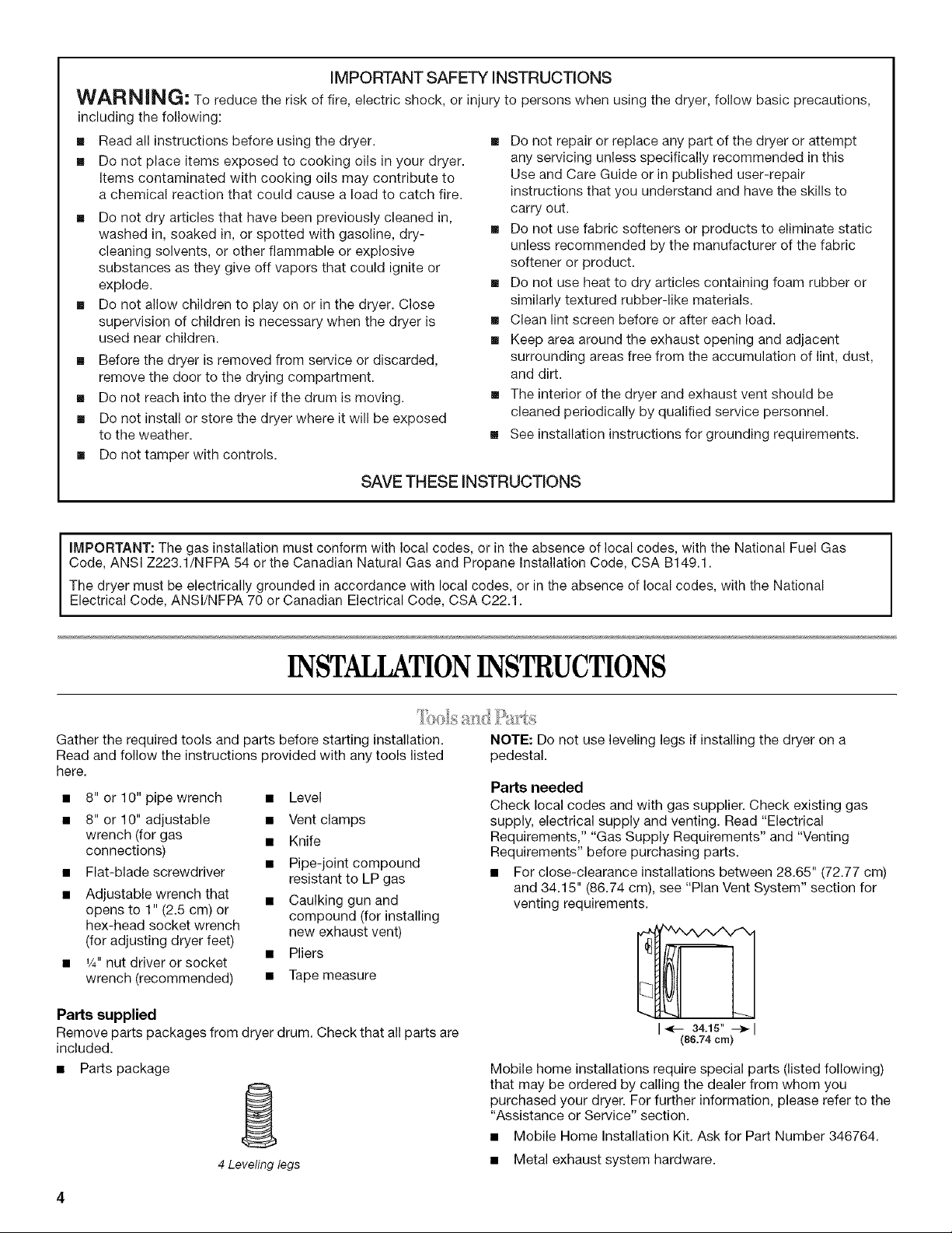
• For close-clearance installations between 28.65" (72.77 cm)
and 34.15" (86.74 cm), see "Plan Vent System" section for
venting requirements.
Parts supplied
Remove parts packages from dryer drum. Check that all parts are
included.
• Parts package
1
4 Leveling legs
I*- 34.15"--_1
(86.74 crn)
Mobile home installations require special parts (listed following)
that may be ordered by calling the dealer from whom you
purchased your dryer. For further information, please refer to the
"Assistance or Service" section.
• Mobile Home Installation Kit. Ask for Part Number 346764.
• Metal exhaust system hardware.
Areyouplacingthedryeronapedestal?Youhavetheoptionof
purchasingpedestalsofdifferentheightsseparatelyforthisdryer.
Youmayselecta10"(25.4cm)pedestalora15.5"(39.4cm)
pedestalwithashelfandbindividers.Thesepedestalswilladdto
thetotalheightofthedryerforatotalheightofapproximately46"
(116.8cm)or51.5"(130.8cm),respectively.
Foragarageinstallation,youwillneedtoplacethedryeratleast
18"(46cm)abovethefloor.
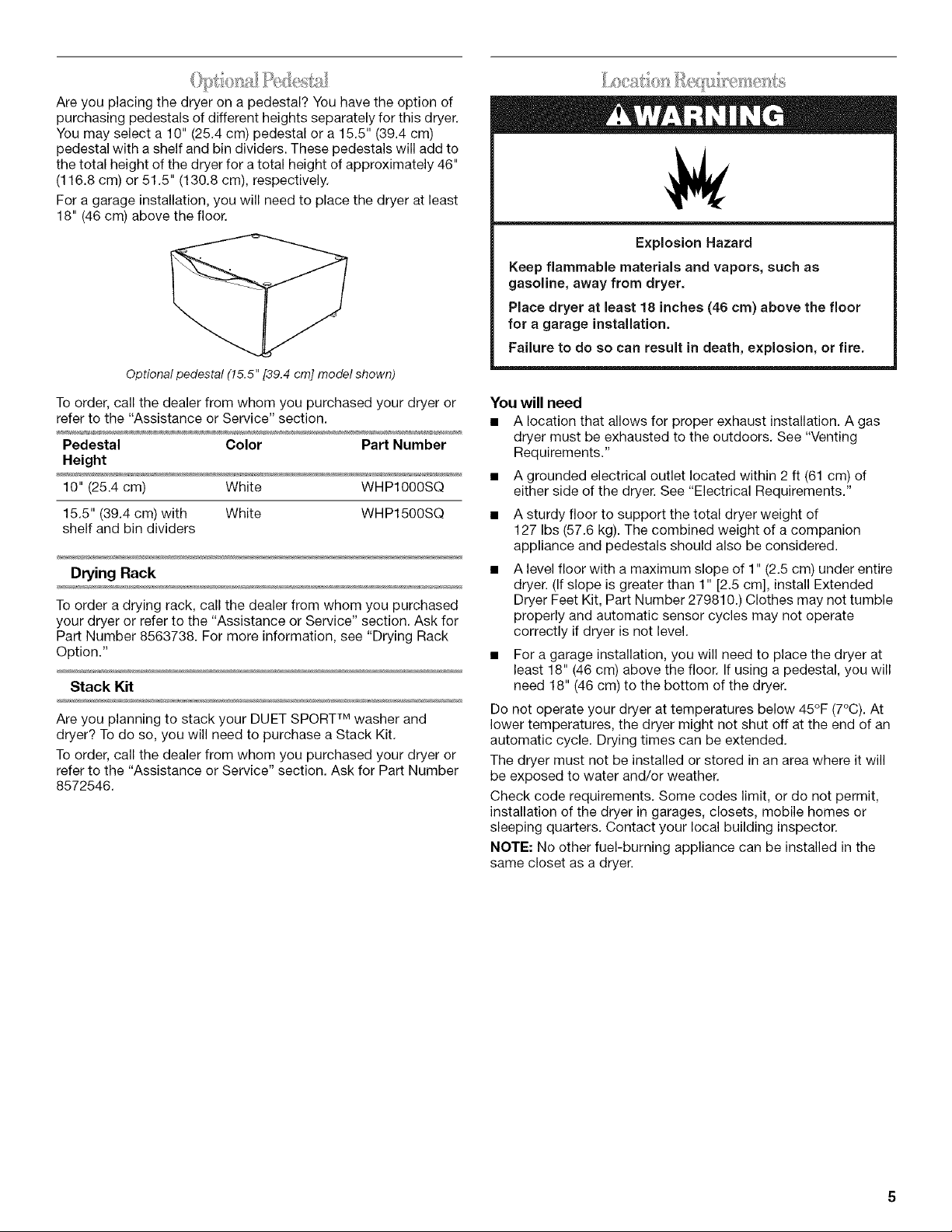
Optional pedestal (15.5" [39.4 cm] model shown)
Explosion Hazard
Keep flammable materials and vapors, such as
gasoline, away from dryer.
Place dryer at least 18 inches (46 cm) above the floor
for a garage installation.
Failure to do so can result in death, explosion, or fire.
To order, call the dealer from whom you purchased your dryer or
refer to the "Assistance or Service" section.
Pedestal Color Part Number
Height
10" (25.4 cm) White WHP1000SQ
15.5" (39.4 cm) with White WHP1500SQ
shelf and bin dividers
Drying Rack
To order a drying rack, call the dealer from whom you purchased
your dryer or refer to the "Assistance or Service" section. Ask for
Part Number 8563738. For more information, see "Drying Rack
Option."
Stack Kit
Are you planning to stack your DUET SPORT TM washer and
dryer? To do so, you will need to purchase a Stack Kit.
To order, call the dealer from whom you purchased your dryer or
refer to the "Assistance or Service" section. Ask for Part Number
8572546.
You will need
• A location that allows for proper exhaust installation. A gas
dryer must be exhausted to the outdoors. See "Venting
Requirements."
• A grounded electrical outlet located within 2 ft (61 cm) of
either side of the dryer. See "Electrical Requirements."
• A sturdy floor to support the total dryer weight of
127 Ibs (57.6 kg). The combined weight of a companion
appliance and pedestals should also be considered.
A level floor with a maximum slope of 1" (2.5 cm) under entire
dryer. (If slope is greater than 1" [2.5 cm], install Extended
Dryer Feet Kit, Part Number 279810.) Clothes may not tumble
properly and automatic sensor cycles may not operate
correctly if dryer is not level.
• For a garage installation, you will need to place the dryer at
least 18" (46 cm) above the floor. If using a pedestal, you will
need 18" (46 cm) to the bottom of the dryer.
Do not operate your dryer at temperatures below 45°F (7°C). At
lower temperatures, the dryer might not shut off at the end of an
automatic cycle. Drying times can be extended.
The dryer must not be installed or stored in an area where it will
be exposed to water and/or weather.
Check code requirements. Some codes limit, or do not permit,
installation of the dryer in garages, closets, mobile homes or
sleeping quarters. Contact your local building inspector.
NOTE: No other fuel-burning appliance can be installed in the
same closet as a dryer.

Installation clearances
The location must be large enough to allow the dryer door to
open fully.
Dryer Dimensions
Closet installation - Dryer only
_'_ ,
48 in?
3"*
• {7.6 cm)
36"
(91,4 crn)
*28.65"
(72,77 cm), 27"
(68,6 cm)
*Most installations require a minimum 5" (12.7 cm) clearance
behind the dryer for the exhaust vent with elbow, See "Venting
Requirements,"
Installation spacing for recessed area or closet installation
The following spacing dimensions are recommended for this
dryer. This dryer has been tested for spacing of O" (Ocm)
clearance on the sides and rear. Recommended spacing should
be considered for the following reasons:
• Additional spacing should be considered for ease of
installation and servicing.
• Additional clearances might be required for wall, door and
floor moldings.
• Additional spacing should be considered on all sides of the
dryer to reduce noise transfer.
For closet installation, with a door, minimum ventilation
openings in the top and bottom of the door are required.
Louvered doors with equivalent ventilation openings are
acceptable.
• Companion appliance spacing should also be considered.
Custom undercounter installation - Dryer only
-. 2"*
ll-qHlllll I I 24in? _
+
LI ,1880o2,
11"*_2868"÷18"**1
{2.5crn) (72.77 crn)(12.7crn)
A
A. Side view - closet or confined area
B. Closet door with vents
*Required spacing
**For side or bottom venting, O"(O cm) spacing is allowed.
Recessed or closet installation - Dryer on pedestal
_" (7.6 cm)
i!
1,,-_ I_-- 27"--_11-_--1"
(2.5 cm) (68.6 crn) {2.5 crn) {2.5 crn)
A B
A.Recessed area
B.Side view - closet or confined area
*Required spacing
**For side or bottom venting, O"(Ocm) spacing is allowed.
Recommended installation spacing for cabinet
installation
i"*11<- 28.68"-_15"**1
{72.77cm) (12.7crn)
3"*
36"rnin
" ilI I1 11II
*Required spacing
1"* _ _-_27"---}_ "_-- 1"*
(2.5 crn) (68 6 crn) (2.5 crn)
• For cabinet installation, with a door, minimum ventilation
openings in the top of the cabinet are required.
_ (17.8era)_17.8 era)
9"*
(22.9 cm)
J
8"** 28.65" 1;' 1" 27" 1"
(12.7 crn) (72.77 crn) (2.5 crn) (2.5 cm)(68.6 crn) (2.5 crn)
*Required spacing
**For side or bottom venting, O"(O cm) spacing is allowed.
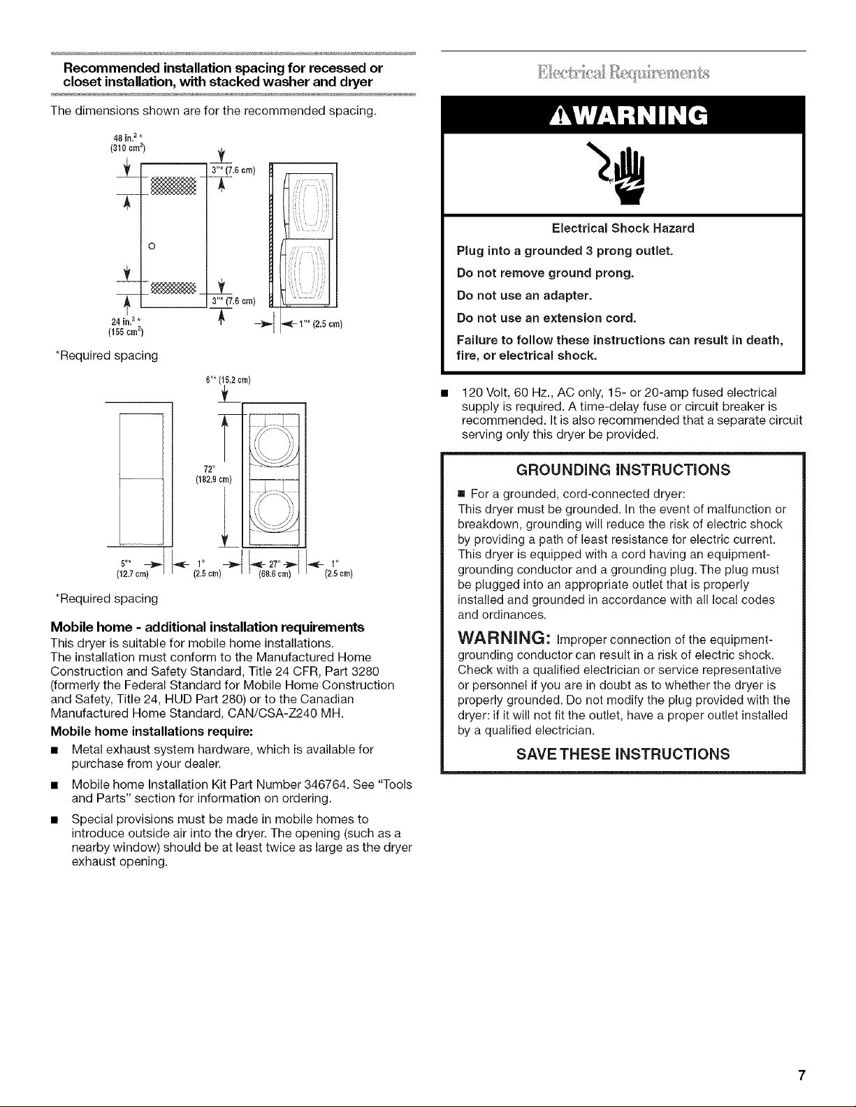
Recommended installation spacing for recessed or
closet installation, with stacked washer and dryer
The dimensions shown are for the recommended spacing.
46 in.2*
{310cm2)
2NNN
o
±
24 in.2 *
(166crn2)
•Required spacing
Electrical Shock Hazard
Plug into a grounded 3 prong outlet.
Do not remove ground prong.
Do not use an adapter.
Do not use an extension cord.
Failure to follow these instructions can result in death,
fire, or electrical shock.
6"*(_.2 cm)
i
6"* --_-
(12.7cm)
72"
(182.9 cm)
2.5crn 68.6 crn
/2!;0ml
*Required spacing
Mobile home - additional installation requirements
This dryer is suitable for mobile home installations.
The installation must conform to the Manufactured Home
Construction and Safety Standard, Title 24 CFR, Part 3280
(formerly the Federal Standard for Mobile Home Construction
and Safety, Title 24, HUD Part 280) or to the Canadian
Manufactured Home Standard, CAN/CSA-Z240 MH.
Mobile home installations require:
[] Metal exhaust system hardware, which is available for
purchase from your dealer.
Mobile home Installation Kit Part Number 346764. See "Tools
[]
and Parts" section for information on ordering.
[]
Special provisions must be made in mobile homes to
introduce outside air into the dryer. The opening (such as a
nearby window) should be at least twice as large as the dryer
exhaust opening.
120 Volt, 60 Hz., AC only, 15- or 20-amp fused electrical
supply is required. A time-delay fuse or circuit breaker is
recommended. It is also recommended that a separate circuit
serving only this dryer be provided.
GROUNDING iNSTRUCTiONS
[] For a grounded, cord-connected dryer:
This dryer must be grounded. In the event of malfunction or
breakdown, grounding will reduce the risk of electric shock
by providing a path of least resistance for electric current.
This dryer is equipped with a cord having an equipment-
grounding conductor and a grounding plug. The plug must
be plugged into an appropriate outlet that is properly
installed and grounded in accordance with all local codes
and ordinances.
WARNING: Improper connection of the equipment-
grounding conductor can result in a risk of electric shock.
Check with a qualified electrician or service representative
or personnel ifyou are in doubt as to whether the dryer is
properly grounded. Do not modify the plug provided with the
dryer: if it will not fit the outlet, have a proper outlet installed
by a qualified electrician.
SAVE THESE INSTRUCTIONS
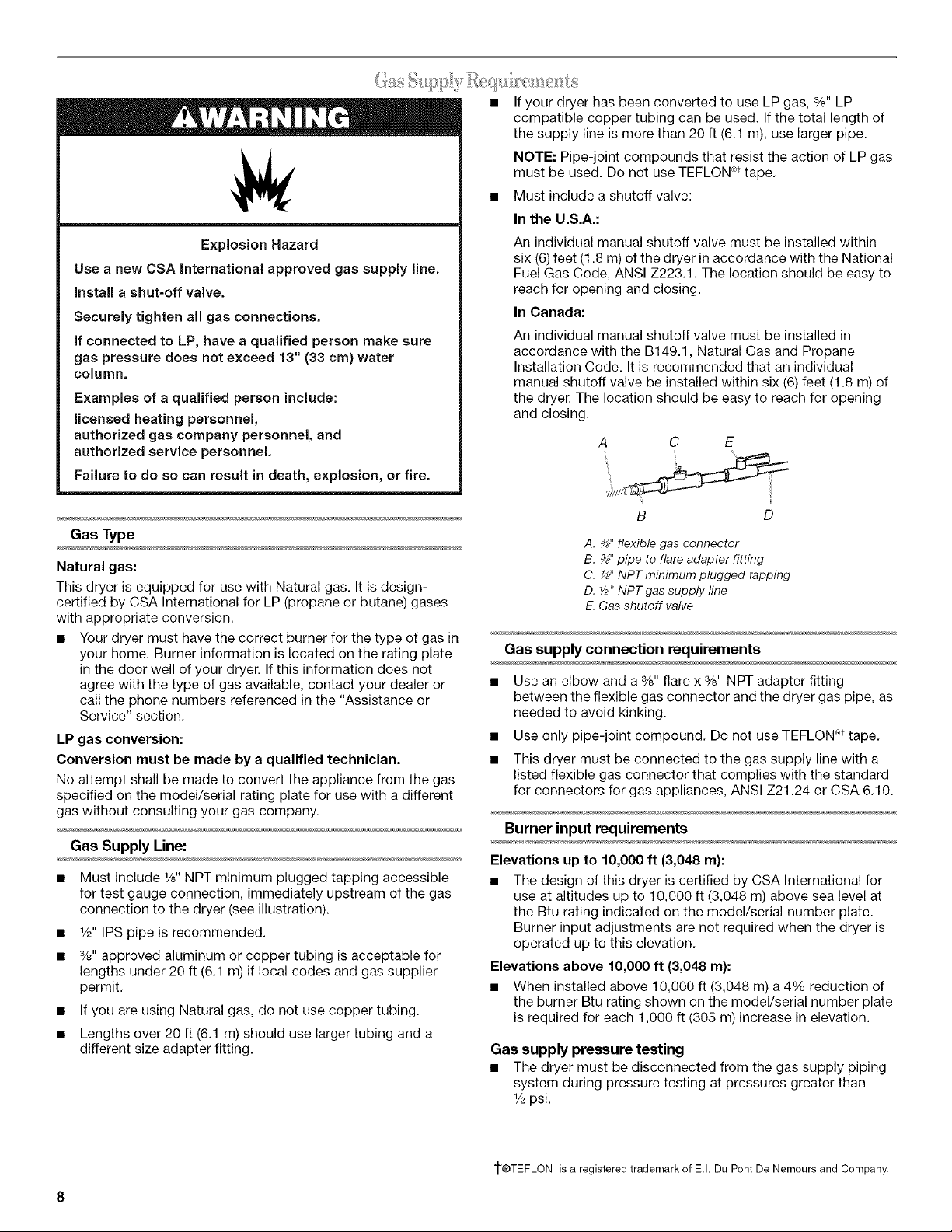
Explosion Hazard
Use a new CSA international approved gas supply line.
Install a shut=off valve,
Securely tighten all gas connections.
(f connected to LP, have a qualified person make sure
gas pressure does not exceed 13" (33 cm) water
column.
Examples of a qualified person include:
licensed heating personnel,
authorized gas company personnel, and
authorized service personnel,
Failure to do so can result in death, explosion, or fire.
Gas Type
Natural gas:
This dryer is equipped for use with Natural gas. It is design-
certified by CSA International for LP (propane or butane) gases
with appropriate conversion.
• Your dryer must have the correct burner for the type of gas in
your home. Burner information is located on the rating plate
in the door well of your dryer. Ifthis information does not
agree with the type of gas available, contact your dealer or
call the phone numbers referenced in the "Assistance or
Service" section.
LP gas conversion:
Conversion must be made by a qualified technician.
No attempt shall be made to convert the appliance from the gas
specified on the model/serial rating plate for use with a different
gas without consulting your gas company.
Gas Supply Line:
• Must include r/8"NPT minimum plugged tapping accessible
for test gauge connection, immediately upstream of the gas
connection to the dryer (see illustration).
• rA" IPS pipe is recommended.
• %" approved aluminum or copper tubing is acceptable for
lengths under 20 ft (6.1 m) if local codes and gas supplier
permit.
• If you are using Natural gas, do not use copper tubing.
• Lengths over 20 ft (6.1 m) should use larger tubing and a
different size adapter fitting.
If your dryer has been converted to use LP gas, %" LP
compatible copper tubing can be used. If the total length of
the supply line is more than 20 ft (6.1 m), use larger pipe.
NOTE: Pipe-joint compounds that resist the action of LP gas
must be used. Do not use TEFLON _t tape.
• Must include a shutoff valve:
In the U.S.A.:
An individual manual shutoff valve must be installed within
six (6) feet (1.8 m) of the dryer in accordance with the National
Fuel Gas Code, ANSI Z223.1. The location should be easy to
reach for opening and closing.
In Canada:
An individual manual shutoff valve must be installed in
accordance with the B149.1, Natural Gas and Propane
Installation Code. It is recommended that an individual
manual shutoff valve be installed within six (6) feet (1.8 m) of
the dryer. The location should be easy to reach for opening
and closing.
A C E
B D
A. _" flexible gas connector
B. _" pipe to flare adapterfitting
C. _" NPT minimum plugged tapping
D. F2" NPT gas supply line
E. Gas shutoff valve
Gas supply connection requirements
• Use an elbow and a %" flare x %" NPT adapter fitting
between the flexible gas connector and the dryer gas pipe, as
needed to avoid kinking.
• Use only pipe-joint compound. Do not use TEFLON _t tape.
• This dryer must be connected to the gas supply line with a
listed flexible gas connector that complies with the standard
for connectors for gas appliances, ANSI Z21.24 or CSA 6.10.
Burner input requirements
Elevations up to 10,000 ft (3,048 m):
• The design of this dryer is certified by CSA International for
use at altitudes up to 10,000 ft (3,048 m) above sea level at
the Btu rating indicated on the model/serial number plate.
Burner input adjustments are not required when the dryer is
operated up to this elevation.
Elevations above 10,000 ft (3,048 m):
• When installed above 10,000 ft (3,048 m) a 4% reduction of
the burner Btu rating shown on the model/serial number plate
is required for each 1,000 ft (305 m) increase in elevation.
Gas supply pressure testing
• The dryer must be disconnected from the gas supply piping
system during pressure testing at pressures greater than
r/2psi.
1-®TEFLON is a registered trademark of E.I. Du Pont De Nemours and Company.

Dryer gas pipe
If this is a new vent system
• The gas pipe that comes out through the rear of your dryer
has a %" male pipe thread.
0,J4,,/ I ........B
A. _/p"NPT gas supply line
B. _" NPT dryer pipe
*NOTE: If the dryer is mounted on a pedestal, the gas pipe height
must be an additional 10" (25.4 cm) or 15.5" (39.4 cm) from the
floor, depending on the pedestal model. For a garage
installation, the gas pipe height must be an additional
18" (46 cm) from the floor.
Fire Hazard
Use a heavy metal vent.
Do not use a plastic vent.
Do not use a metal foil vent.
Failure to follow these instructions can result in death
or fire.
Vent material
• Use a heavy metal vent. Do not use plastic or metal foil vent.
• 4" (10.2 cm) heavy metal exhaust vent and clamps must be
used. DURASAFF Mventing products are recommended.
4" (10.2cm) heavymetal exhaust vent
DURASAFF Mvent products can be purchased from your
dealer or by calling Whirlpool Parts and Accessories. For
more information, see the "Assistance or Service" section.
Rigid metal vent
• For best drying performance, rigid metal vents are
recommended.
• Rigid metal vent is recommended to avoid crushing and
kinking.
Flexible metal vent
• Flexible metal vents are acceptable only if accessible for
cleaning.
Flexible metal vent must be fully extended and supported
when the dryer is in its final location.
Remove excess flexible metal vent to avoid sagging and
kinking that may result in reduced airflow and poor
performance.
Do not install flexible metal vent in enclosed walls, ceilings or
floors.
Elbows
45° elbows provide better airflow than 90° elbows.
WARNING: To reduce the risk of fire, this dryer MUST BE
EXHAUSTED OUTDOORS.
IMPORTANT: Observe all governing codes and ordinances.
The dryer exhaust must not be connected into any gas vent,
chimney, wall, ceiling or a concealed space of a building.
If using an existing vent system
• Clean lint from the entire length of the system and make sure
exhaust hood is not plugged with lint.
• Replace any plastic or metal foil vent with rigid or flexible
heavy metal vent.
• Review Vent system chart. Modify existing vent system if
necessary to achieve the best drying performance.
Good Better
Clamps
Use clamps to seal all joints.
Exhaust vent must not be connected or secured with screws
or other fastening devices that extend into the interior of the
duct. Do not use duct tape.
Clamp
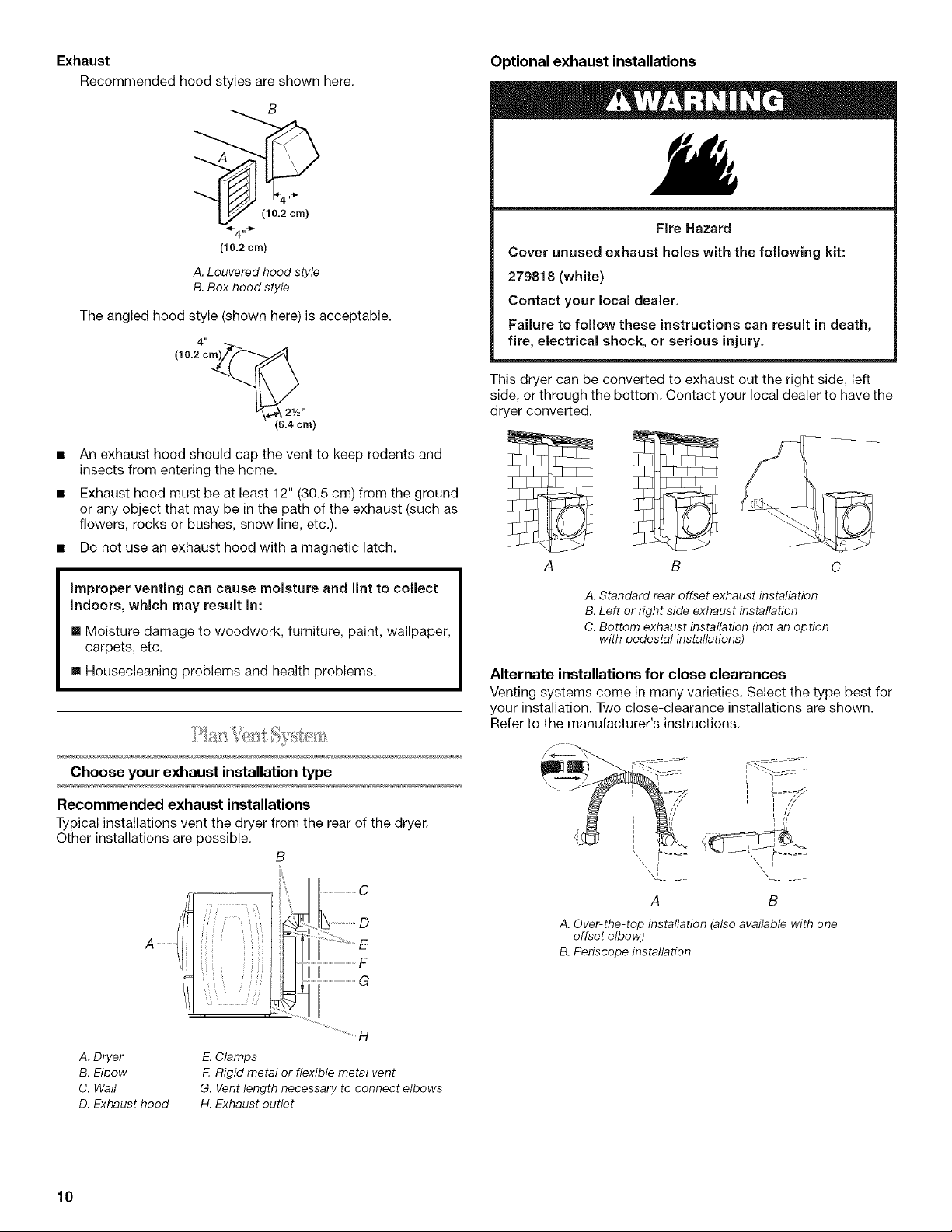
Exhaust
Recommended hood styles are shown here.
(10.2cm)
A. Louvered hood style
B.Box hood style
The angled hood style (shown here) is acceptable.
4-"
Optional exhaust installations
Fire Hazard
Cover unused exhaust holes with the following kit:
279818 (white)
Contact your local dealer.
Failure to follow these instructions can result in death,
fire, electrical shock, or serious injury.
(10.2 cm)__
• An exhaust hood should cap the vent to keep rodents and
insects from entering the home.
• Exhaust hood must be at least 12" (30.5 cm) from the ground
or any object that may be in the path of the exhaust (such as
flowers, rocks or bushes, snow line, etc.).
• Do not use an exhaust hood with a magnetic latch.
Improper venting can cause moisture and lint to collect
indoors, which may result in:
[] Moisture damage to woodwork, furniture, paint, wallpaper,
carpets, etc.
[] Housecleaning problems and health problems.
Choose your exhaust installation type
Recommended exhaust installations
Typical installations vent the dryer from the rear of the dryer.
Other installations are possible.
B
--C
A--
This dryer can be converted to exhaust out the right side, left
side, or through the bottom. Contact your local dealer to have the
dryer converted.
A B
A. Standard rear offset exhaust installation
B. Left or right side exhaust installation
C. Bottom exhaust installation (not an option
with pedestal installations)
Alternate installations for close clearances
Venting systems come in many varieties. Select the type best for
your installation. Two close-clearance installations are shown.
Refer to the manufacturer's instructions.
I
i
A B
A. Over-the-top installation (also available with one
offset elbow)
B. Periscope installation
i
\_ iI
A. Dryer
B. Elbow
C. Wall
D. Exhaust hood
10
....................................G
i ....................................F
E. Clamps
E Rigid metal or flexible metal vent
G. Vent length necessary to connect elbows
H. Exhaust outlet
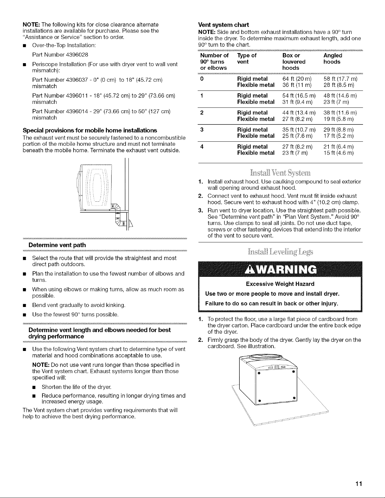
NOTE: The following kits for close clearance alternate
installations are available for purchase. Please see the
"Assistance or Service" section to order.
• Over-the-Top Installation:
Part Number 4396028
• Periscope Installation (For use with dryer vent to wall vent
mismatch):
Part Number 4396037 - 0" (0 cm) to 18" (45.72 cm)
mismatch
Part Number 4396011 - 18" (45.72 cm) to 29" (73.66 cm)
mismatch
Part Number 4396014 - 29" (73.66 cm) to 50" (127 cm)
mismatch
Special provisions for mobile home installations
The exhaust vent must be securely fastened to a noncombustible
portion of the mobile home structure and must not terminate
beneath the mobile home. Terminate the exhaust vent outside.
Determine vent path
Vent system chart
NOTE: Side and bottom exhaust installations have a 90° turn
inside the dryer. To determine maximum exhaust length, add one
90° turn to the chart.
Number of Type of Box or Angled
90° turns vent Iouvered hoods
or elbows hoods
0 Rigid metal 64 ft (20 m) 58 ft (17.7 m)
Flexible metal 36 ft (11 m) 28 ft (8.5 m)
1 Rigid metal 54 ft (16.5 m) 48 ft (14.6 m)
Flexible metal 31 ft (9.4 m) 23 ft (7 m)
2 Rigid metal 44 ft (13.4 m) 38 ft (11.6 m)
Flexible metal 27 ft (8.2 m) 19 ft (5.8 m)
3 Rigid metal 35 ft (10.7 m) 29 ft (8.8 m)
Flexible metal 25 ft (7.6 m) 17 ft (5.2 m)
4 Rigid metal 27 ft (8.2 m) 21 ft (6.4 m)
Flexible metal 23 ft (7 m) 15 ft (4.6 m)
1. Install exhaust hood. Use caulking compound to seal exterior
wall opening around exhaust hood.
2. Connect vent to exhaust hood. Vent must fit inside exhaust
hood. Secure vent to exhaust hood with 4" (10.2 cm) clamp.
3. Run vent to dryer location. Use the straightest path possible.
See "Determine vent path" in "Plan Vent System." Avoid 90 °
turns. Use clamps to seal all joints. Do not use duct tape,
screws or other fastening devices that extend into the interior
of the vent to secure vent.
• Select the route that will provide the straightest and most
direct path outdoors.
• Plan the installation to use the fewest number of elbows and
turns.
• When using elbows or making turns, allow as much room as
possible.
• Bend vent gradually to avoid kinking.
• Use the fewest 90 ° turns possible.
Determine vent length and elbows needed for best
drying performance
• Use the following Vent system chart to determine type of vent
material and hood combinations acceptable to use.
NOTE: Do not use vent runs longer than those specified in
the Vent system chart. Exhaust systems longer than those
specified will:
• Shorten the life of the dryer.
• Reduce performance, resulting in longer drying times and
increased energy usage.
The Vent system chart provides venting requirements that will
help to achieve the best drying performance.
Excessive Weight Hazard
Use two or more people to move and install dryer.
Failure to do so can result in back or other injury.
1. To protect the floor, use a large flat piece of cardboard from
the dryer carton. Place cardboard under the entire back edge
of the dryer.
2. Firmly grasp the body of the dryer. Gently lay the dryer on the
cardboard. See illustration.
11

3. Examine the leveling legs. Find the diamond marking.
!
4. Screw the legs into the leg holes by hand. Use a wrench to
finish turning the legs until the diamond marking is no longer
visible.
5. Place a carton corner post from dryer packaging under each
of the 2 dryer back corners. Stand the dryer up. Slide the
dryer on the corner posts until it is close to its final location.
Leave enough room to connect the exhaust vent or gas line.
For mobile home use
Gas dryers must be securely fastened to the floor at the time of
installation.
Mobile home installations require a Mobile Home Installation Kit.
For more information, please reference the service numbers in
the "Assistance or Service" section.
1=
Remove the red cap from the gas pipe.
2.
Using a wrench to tighten, connect the gas supply to the
dryer. Use pipe-joint compound on the threads of all non-
flared male fittings. If flexible metal tubing is used, be sure
there are no kinks.
A................................_ _ ..............................B
A. Flared male fitting
B. Non-flared male fitting
f
/
/
A
\
C
A. _" flexible gas connector
B. _" dryer pipe
C. _" to _" pipe elbow
D. _" pipe-to-flare adapter fitting
3=
Open the shutoff valve in the supply line. The valve is open
when the handle is parallel to the gas pipe.
A.Closed valve
B.Open valve
4=
Test all connections by brushing on an approved
noncorrosive leak-detection solution. Bubbles will show a
leak. Correct any leak found.
1. Using a 4" (10.2 cm) clamp, connect vent to exhaust outlet in
dryer. If connecting to existing vent, make sure the vent is
clean. The dryer vent must fit over the dryer exhaust outlet
and inside the exhaust hood. Check that the vent is secured
to exhaust hood with a 4" (10.2 cm) clamp.
2. Move dryer into its final location. Do not crush or kink vent.
3. (On gas models) Check that there are no kinks in the flexible
gas line.
4. Once the exhaust vent connection is made, remove the
corner posts and cardboard.
NOTE: For LP gas connections, you must use pipe-joint
compound resistant to the action of LP gas. Do not use
TEFLON_t tape.
A combination of pipe fittings must be used to connect the
dryer to the existing gas line. Shown is a recommended
connection. Your connection may be different, according to
the supply line type, size and location.
1-®TEFLON is a registered trademark of E.I. Du Pont De Nemours and Company.
12
Check the levelness of the dryer. Check levelness first side to
side, then front to back.
If the dryer is not level, prop up the dryer using a wood block.
Use a wrench to adjust the legs up or down and check again for
levelness.
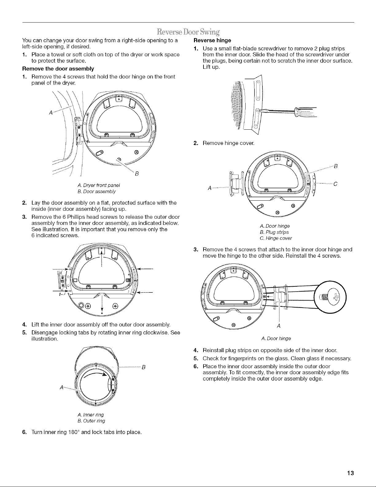
Youcanchangeyourdoorswingfromaright-sideopeningtoa
left-sideopening,ifdesired.
1. Placeatowelorsoftclothontopofthedryerorworkspace
toprotectthesurface.
Removethedoorassembly
1. Removethe4screwsthatholdthedoorhingeonthefront
panelofthedryer.
®
A. Dryer front panel
B. Door assembly
2=
Lay the door assembly on a flat, protected surface with the
inside (inner door assembly) facing up.
3.
Remove the 6 Phillips head screws to release the outer door
assembly from the inner door assembly, as indicated below.
See illustration. It is important that you remove only the
6 indicated screws.
Reverse hinge
1. Use a small flat-blade screwdriver to remove 2 plug strips
from the inner door. Slide the head of the screwdriver under
the plugs, being certain not to scratch the inner door surface.
Lift up.
2=
Remove hinge cover.
A ...................(__
A. Door hinge
B. Plug strips
C. Hinge cover
4. Lift the inner door assembly off the outer door assembly.
5. Disengage locking tabs by rotating inner ring clockwise. See
illustration.
A. Inner ring
B. Outer ring
3=
Remove the 4 screws that attach to the inner door hinge and
move the hinge to the other side. Reinstall the 4 screws.
®
A. Door hinge
4. Reinstall plug strips on opposite side of the inner door.
5. Check for fingerprints on the glass. Clean glass if necessary.
6. Place the inner door assembly inside the outer door
assembly. To fit correctly, the inner door assembly edge fits
completely inside the outer door assembly edge.
6. Turn inner ring 180 ° and lock tabs into place.
13
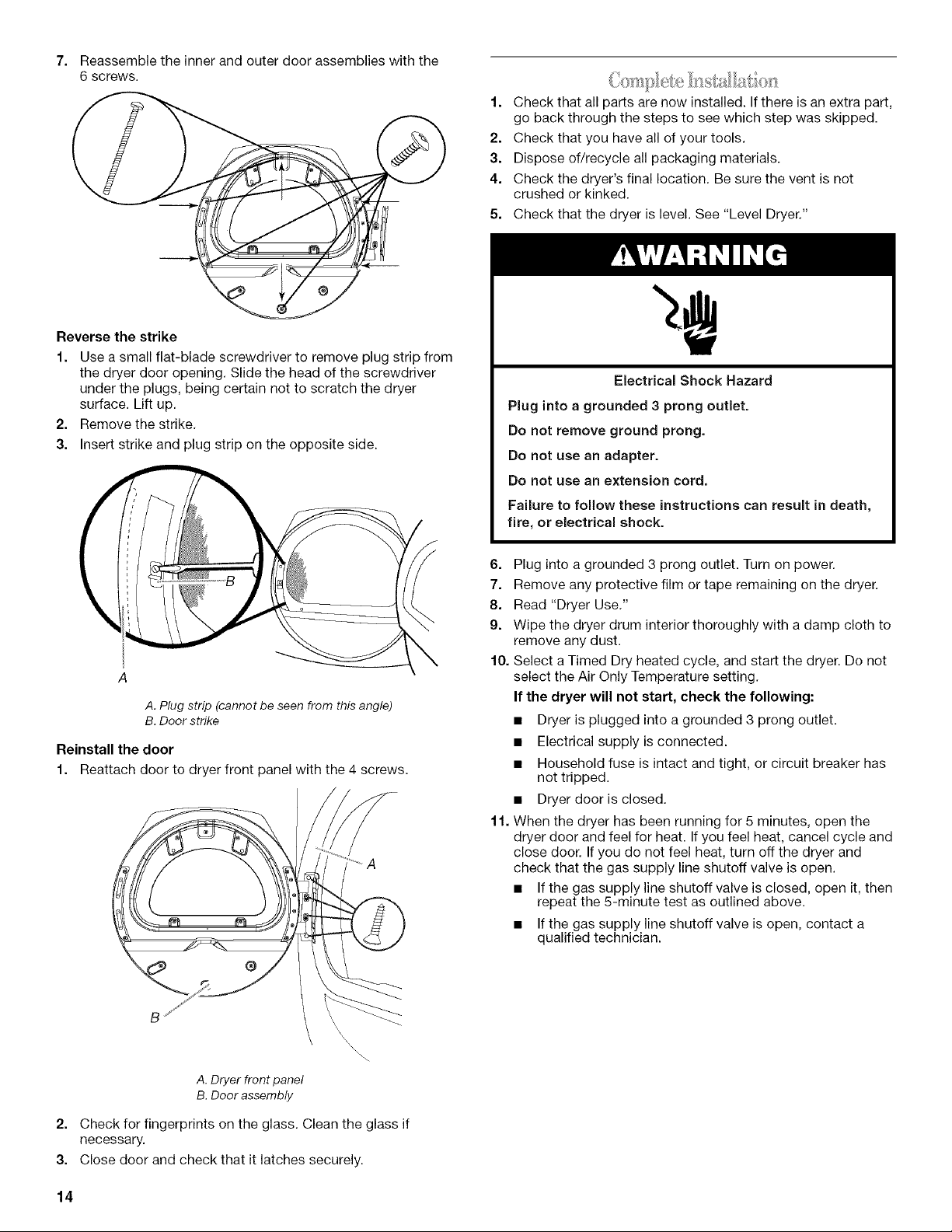
7. Reassemble the inner and outer door assemblies with the
6 screws.
Reverse the strike
1. Use a small flat-blade screwdriver to remove plug strip from
the dryer door opening. Slide the head of the screwdriver
under the plugs, being certain not to scratch the dryer
surface. Lift up.
2. Remove the strike.
3. Insert strike and plug strip on the opposite side.
1. Check that all parts are now installed. If there is an extra part,
go back through the steps to see which step was skipped.
2. Check that you have all of your tools.
3. Dispose of/recycle all packaging materials.
4. Check the dryer's final location. Be sure the vent is not
crushed or kinked.
5. Check that the dryer is level. See "Level Dryer."
Electrical Shock Hazard
Plug into a grounded 3 prong outlet.
Do not remove ground prong.
Do not use an adapter.
Do not use an extension cord,
Failure to follow these instructions can result in death,
fire, or electrical shock.
A
A.Plug strip (cannot be seen from this angle)
B. Door strike
Reinstall the door
1. Reattach door to dryer front panel with the 4 screws.
@
6. Plug into a grounded 3 prong outlet. Turn on power.
7. Remove any protective film or tape remaining on the dryer.
8. Read "Dryer Use."
9. Wipe the dryer drum interior thoroughly with a damp cloth to
remove any dust.
10. Select a Timed Dry heated cycle, and start the dryer. Do not
select the Air Only Temperature setting.
If the dryer will not start, check the following:
• Dryer is plugged into a grounded 3 prong outlet.
• Electrical supply is connected.
• Household fuse is intact and tight, or circuit breaker has
not tripped.
• Dryer door is closed.
11. When the dryer has been running for 5 minutes, open the
dryer door and feel for heat. If you feel heat, cancel cycle and
close door. If you do not feel heat, turn off the dryer and
check that the gas supply line shutoff valve is open.
• If the gas supply line shutoff valve is closed, open it, then
repeat the 5-minute test as outlined above.
• If the gas supply line shutoff valve is open, contact a
qualified technician.
A.Dryer front panel
B.Door assembly
2. Check for fingerprints on the glass. Clean the glass if
necessary.
3. Close door and check that it latches securely.
14
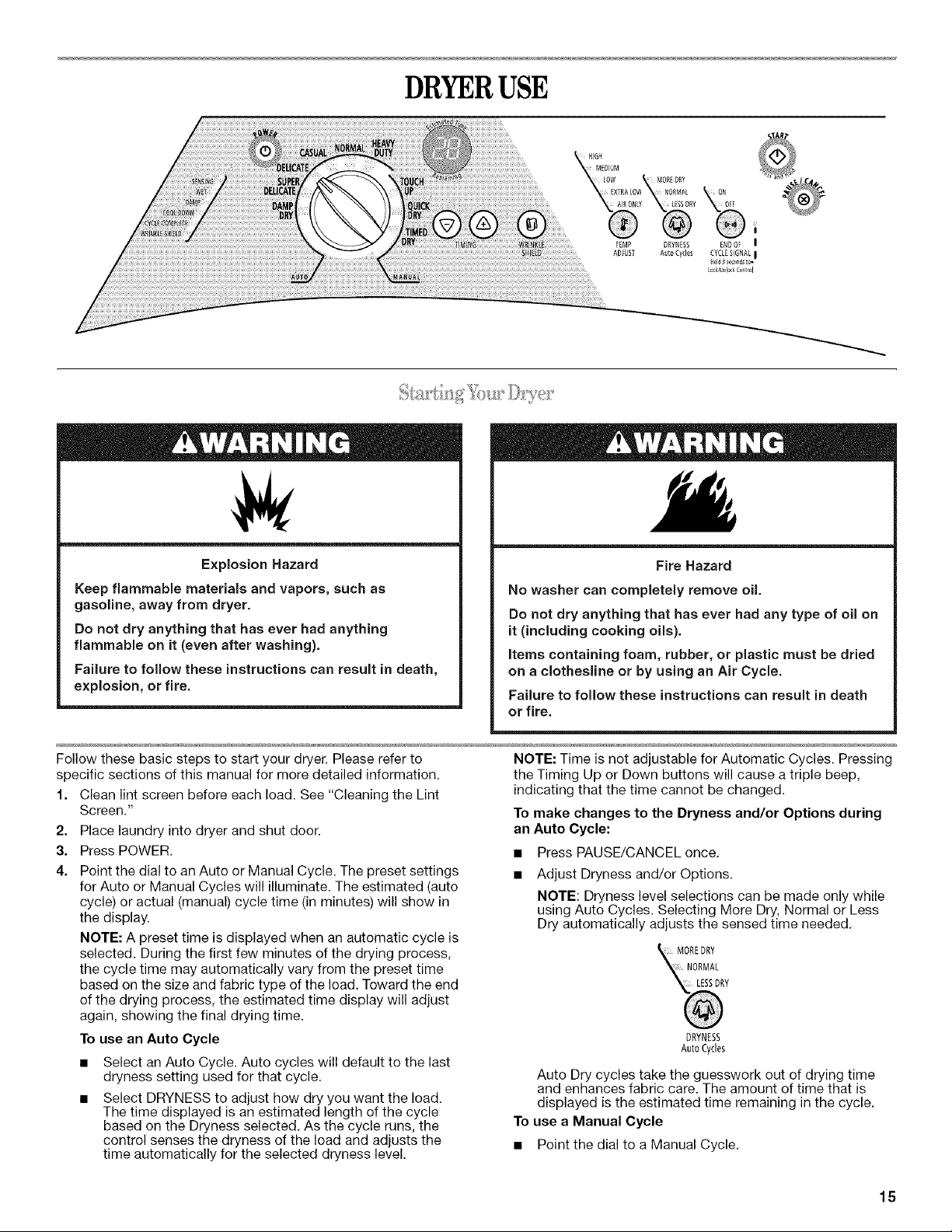
DRYERUSE
Explosion Hazard
Keep flammable materials and vapors, such as
gasoline, away from dryer.
Do not dry anything that has ever had anything
flammable on it (even after washing).
Failure to follow these instructions can result in death,
explosion, or fire.
Follow these basic steps to start your dryer. Please refer to
specific sections of this manual for more detailed information.
f. Clean lint screen before each load. See "Cleaning the Lint
Screen."
2. Place laundry into dryer and shut door.
3. Press POWER.
4. Point the dial to an Auto or Manual Cycle. The preset settings
for Auto or Manual Cycles will illuminate. The estimated (auto
cycle) or actual (manual) cycle time (in minutes) will show in
the display.
NOTE: A preset time is displayed when an automatic cycle is
selected. During the first few minutes of the drying process,
the cycle time may automatically vary from the preset time
based on the size and fabric type of the load. Toward the end
of the drying process, the estimated time display will adjust
again, showing the final drying time.
To use an Auto Cycle
Select an Auto Cycle. Auto cycles will default to the last
dryness setting used for that cycle.
Select DRYNESS to adjust how dry you want the load.
The time displayed is an estimated length of the cycle
based on the Dryness selected. As the cycle runs, the
control senses the dryness of the load and adjusts the
time automatically for the selected dryness level.
Fire Hazard
No washer can completely remove oil.
Do not dry anything that has ever had any type of oil on
it (including cooking oils).
Items containing foam, rubber, or plastic must be dried
on a clothesline or by using an Air Cycle.
Failure to follow these instructions can result in death
or fire.
NOTE: Time is not adjustable for Automatic Cycles. Pressing
the Timing Up or Down buttons will cause a triple beep,
indicating that the time cannot be changed.
To make changes to the Dryness and/or Options during
an Auto Cycle:
• Press PAUSE/CANCEL once.
Adjust Dryness and/or Options.
NOTE: Dryness level selections can be made only while
using Auto Cycles. Selecting More Dry, Normal or Less
Dry automatically adjusts the sensed time needed.
MOREDRY
NORMAl.
N'
DRYNESS
AutoCycles
Auto Dry cycles take the guesswork out of drying time
and enhances fabric care. The amount of time that is
displayed is the estimated time remaining in the cycle.
To use a Manual Cycle
• Point the dial to a Manual Cycle.
15
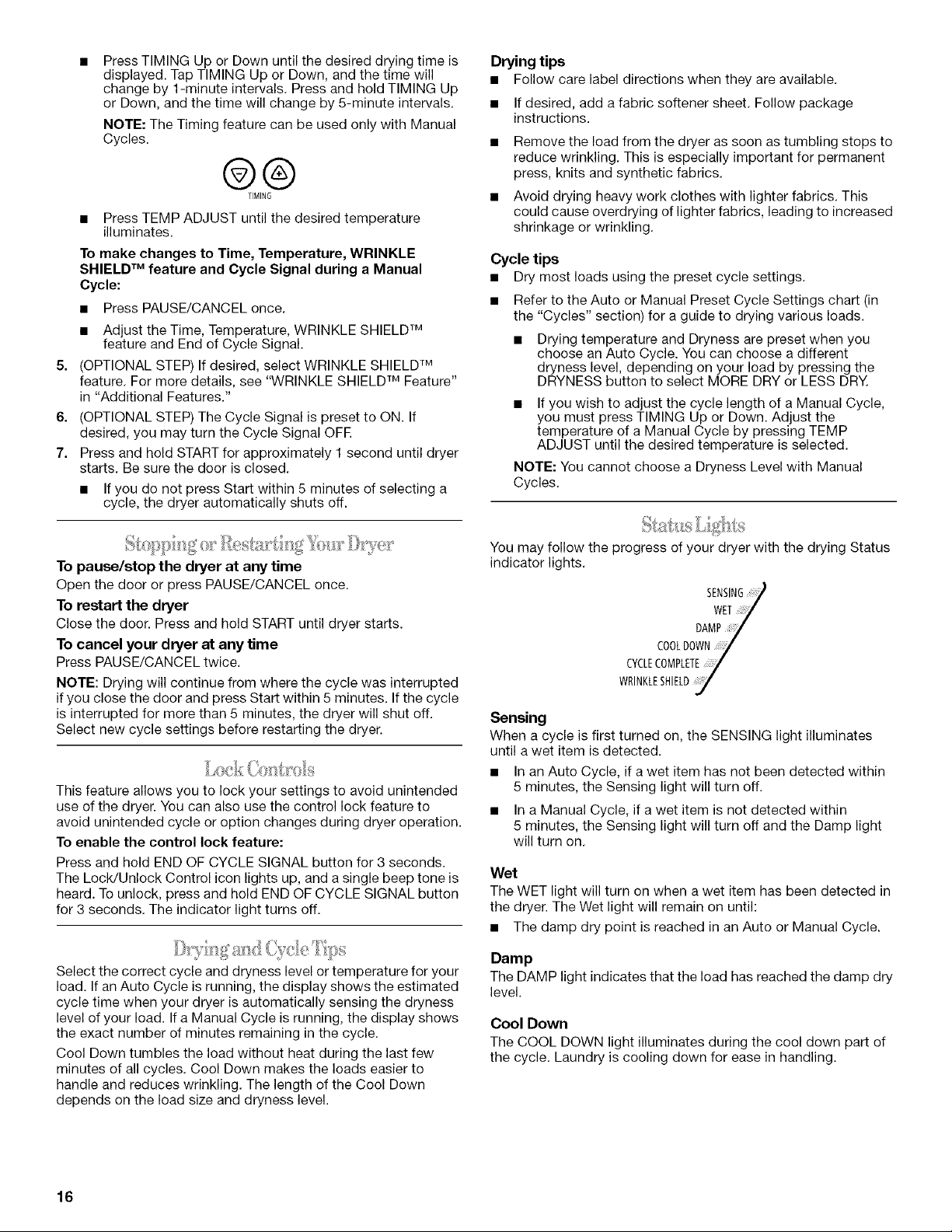
Press TIMING Up or Down until the desired drying time is
• Drying tips
displayed. Tap TIMING Up or Down, and the time will
change by 1-minute intervals. Press and hold TIMING Up
or Down, and the time will change by 5-minute intervals.
NOTE: The Timing feature can be used only with Manual
Cycles.
• Follow care label directions when they areavailable,
• If desired, add a fabric softener sheet. Follow package
• Remove the load from the dryer as soon as tumbling stops to
@®
TIMING
• Press TEMP ADJUST until the desired temperature
illuminates.
To make changes to Time, Temperature, WRINKLE
SHIELD TM feature and Cycle Signal during a Manual
Cycle:
• Press PAUSE/CANCEL once.
• Adjust the Time, Temperature, WRINKLE SHIELD TM
feature and End of Cycle Signal.
5. (OPTIONAL STEP) If desired, select WRINKLE SHIELD TM
feature. For more details, see "WRINKLE SHIELD TM Feature"
in "Additional Features."
6. (OPTIONAL STEP) The Cycle Signal is preset to ON. If
desired, you may turn the Cycle Signal OFE
7. Press and hold START for approximately 1 second until dryer
starts. Be sure the door is closed.
• If you do not press Start within 5 minutes of selecting a
cycle, the dryer automatically shuts off.
• Avoid drying heavy work clothes with lighter fabrics. This
Cycle tips
• Dry most loads using the preset cycle settings.
• Refer to the Auto or Manual Preset Cycle Settings chart (in
instructions.
reduce wrinkling. This is especially important for permanent
press, knits and synthetic fabrics.
could cause overdrying of lighter fabrics, leading to increased
shrinkage or wrinkling.
the "Cycles" section) for a guide to drying various loads.
Drying temperature and Dryness are preset when you
choose an Auto Cycle. You can choose a different
dryness level, depending on your load by pressing the
DRYNESS button to select MORE DRY or LESS DRY.
• If you wish to adjust the cycle length of a Manual Cycle,
you must press TIMING Up or Down. Adjust the
temperature of a Manual Cycle by pressing TEMP
ADJUST until the desired temperature is selected.
NOTE: You cannot choose a Dryness Level with Manual
Cycles.
To pause/stop the dryer at any time
Open the door or press PAUSE/CANCEL once.
To restart the dryer
Close the door. Press and hold START until dryer starts.
To cancel your dryer at any time
Press PAUSE/CANCEL twice.
NOTE: Drying will continue from where the cycle was interrupted
if you close the door and press Start within 5 minutes. If the cycle
is interrupted for more than 5 minutes, the dryer will shut off.
Select new cycle settings before restarting the dryer.
This feature allows you to lock your settings to avoid unintended
use of the dryer. You can also use the control lock feature to
avoid unintended cycle or option changes during dryer operation.
To enable the control lock feature:
Press and hold END OF CYCLE SIGNAL button for 3 seconds.
The Lock/Unlock Control icon lights up, and a single beep tone is
heard. To unlock, press and hold END OF CYCLE SIGNAL button
for 3 seconds. The indicator light turns off.
( ,.
Select the correct cycle and dryness level or temperature for your
load. If an Auto Cycle is running, the display shows the estimated
cycle time when your dryer is automatically sensing the dryness
level of your load. If a Manual Cycle is running, the display shows
the exact number of minutes remaining in the cycle.
Cool Down tumbles the load without heat during the last few
minutes of all cycles. Cool Down makes the loads easier to
handle and reduces wrinkling. The length of the Cool Down
depends on the load size and dryness level.
You may follow the progress of your dryer with the drying Status
indicator lights.
SENSING
WET_
DAMP/
COOLDOWN
CYCLECOMPLETE_/
WRINKLESHIELD_/
Sensing
When a cycle is first turned on, the SENSING light illuminates
until a wet item is detected.
• In an Auto Cycle, if a wet item has not been detected within
5 minutes, the Sensing light will turn off.
• In a Manual Cycle, if a wet item is not detected within
5 minutes, the Sensing light will turn off and the Damp light
will turn on.
Wet
The WET light will turn on when a wet item has been detected in
the dryer. The Wet light will remain on until:
• The damp dry point is reached in an Auto or Manual Cycle.
Damp
The DAMP light indicates that the load has reached the damp dry
level.
Cool Down
The COOL DOWN light illuminates during the cool down part of
the cycle. Laundry is cooling down for ease in handling.
16

Cycle Complete
This light illuminates when a drying cycle is finished. Ifthe
WRINKLE SHIELD TM feature has been selected, the WRINKLE
SHIELD TM feature indicator light will also be illuminated.
The Cycle Complete light turns off I hour after the end of a drying
cycle (including the WRINKLE SHIELD TM cycle of 90 minutes),
when Pause/Cancel is pressed, or when the door is opened.
WRINKLE SHIELD TM Feature
The WRINKLE SHIELDTM feature light illuminates when this
option is selected. This indicator stays on with the Cycle
Complete light.
Indicator lights
Other indicator lights on the control panel show when Cycle,
Temp Adjust, and End of Cycle settings are selected.
Select the drying cycle that matches the type of load you are
drying. See Auto Preset or Manual Preset Cycle Settings charts,
HEAVY
cASU T'
DELICATEf1...--..._
SUPER/_"_ XTOUCH
DELICATE///_ \'_ _UP
DAMPII( \\ _\ /I }QUICK
DRYt tt _._ X)) /DRY
k \\ "_ x/' /TIMED
Auto Preset Cycle Settings
Auto Cycles Temp. Time*
Load Type (Minutes)
HEAVY DUTY High 40
Heavyweight mixed loads,
cotton towels, jeans
NORMAL Medium 35
Mixed loads, corduroys, work
clothes, sheets
CASUAL Low 35
Permanent press, synthetics
DELICATE Low 30
Lightweight items, blouses,
synthetics
SUPER DELICATE Extra Low 25
Lingerie
DAMP DRY Low 20
Clothes to come out suitable
for ironing
*Estimated Time with Auto DRYNESS (Normal) setting.
Time will vary depending on load type and load size,
Manual Cycles
Cycle Control knob
Auto Cycles
Auto Cycles allow you to match the cycle to the load you are
drying, See the following Auto Preset Cycle Settings chart, Each
cycle dries certain fabrics at the recommended temperature. A
sensor detects the moisture in the load and automatically adjusts
the drying time for optimal drying,
Heavy Duty
Use this cycle to get High heat for heavyweight mixed loads,
cotton towels or jeans.
Normal
Use this cycle to get Medium heat for drying mixed loads and
sturdy fabrics such as work clothes.
Casual
Use this cycle to get Low heat for drying no-iron fabrics such as
sport shirts, casual business clothes and permanent press
blends.
Delicate
Use this cycle to get Low heat for drying synthetic fabrics,
washable knit fabrics and no-iron finishes.
Super Delicate
Use this cycle to get Extra Low heat to gently dry items such as
lingerie, exercise wear or sheer curtains.
Damp Dry
Use this cycle to dry items to a damp level using Low heat, or to
dry items that do not require an entire drying cycle, Damp dry
items such as jeans (to avoid stiffness) or cotton clothing (to
make ironing easier). The temperature setting on this cycle
cannot be adjusted. Items will have different levels of dampness.
At the end of this cycle, clothes will be damp.
Use Manual Cycles to select a specific amount of drying time and
a drying temperature. When a Manual Cycle is selected, the
ESTIMATED TIME REMAINING display shows the actual time
remaining in your cycle, You can change the actual time in the
cycle by pressing TIMING Up or Down.
Timed Dry
Use this cycle to complete drying if items are still damp after an
Auto Cycle, Timed Dry is also useful for drying heavyweight and
bulky items such as bedspreads and work clothes,
Quick Dry
Use this cycle for drying small loads or loads that need a short
drying time.
Touch Up
Use this setting to help smooth out wrinkles from such items as
clothes packed in a suitcase or items wrinkled from being left in
the dryer too long.
Manual Preset Cycle Settings
Manual Cycles Temp. Default Time
Load Type (Minutes)
TIMED DRY High* 40
Heavyweight, bulky items,
bedspreads, work clothes
QUICK DRY Medium 27
Small loads
TOUCH UP Medium 20
Helps smooth out wrinkles
*The Timed Dry cycle will default to the last temperature used for
Timed Dry.
17
WRINKLE SHIELD TM Feature
The WRINKLE SHIELD TM feature helps smooth out wrinkles that
form when you cannot unload the dryer promptly at the end of a
cycle. During this option, the dryer stops tumbling and then
tumbles again for a brief period.
• Press the WRINKLE SHIELD TM feature to get up to
90 minutes of heat-free, periodic tumbling at the end of a
cycle,
• During the WRINKLE SHIELD TM feature, you may continue
the option after opening and closing the dryer door by
pushing START.
• Cancel at any time by pressing the WRINKLE SHIELD TM
feature button,
NOTE: If you do not select the WRINKLE SHIELD TM feature, the
dryer stops after the cool down period.
Temperature
Temperature settings are used with the Manual Cycles. Press
TEMP ADJUST until the desired temperature setting illuminates.
Temperature modifiers cannot be used with the Auto Cycles.
HIGH
LOW
£XTRALOW
RONLY
TEMP
ADJUST
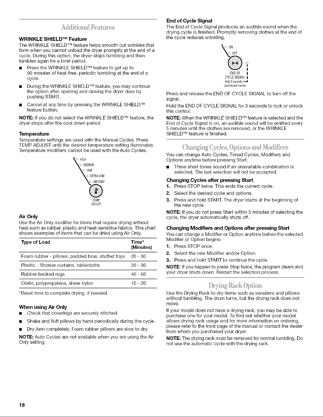
Air Only
Use the Air Only modifier for items that require drying without
heat such as rubber, plastic and heat-sensitive fabrics. This chart
shows examples of items that can be dried using Air Only.
Type of Load Time*
(Minutes)
Foam rubber - pillows, padded bras, stuffed toys 20 - 30
Plastic - Shower curtains, tablecloths 20 - 30
Rubber-backed rugs 40 - 50
Olefin, polypropylene, sheer nylon 10 - 20
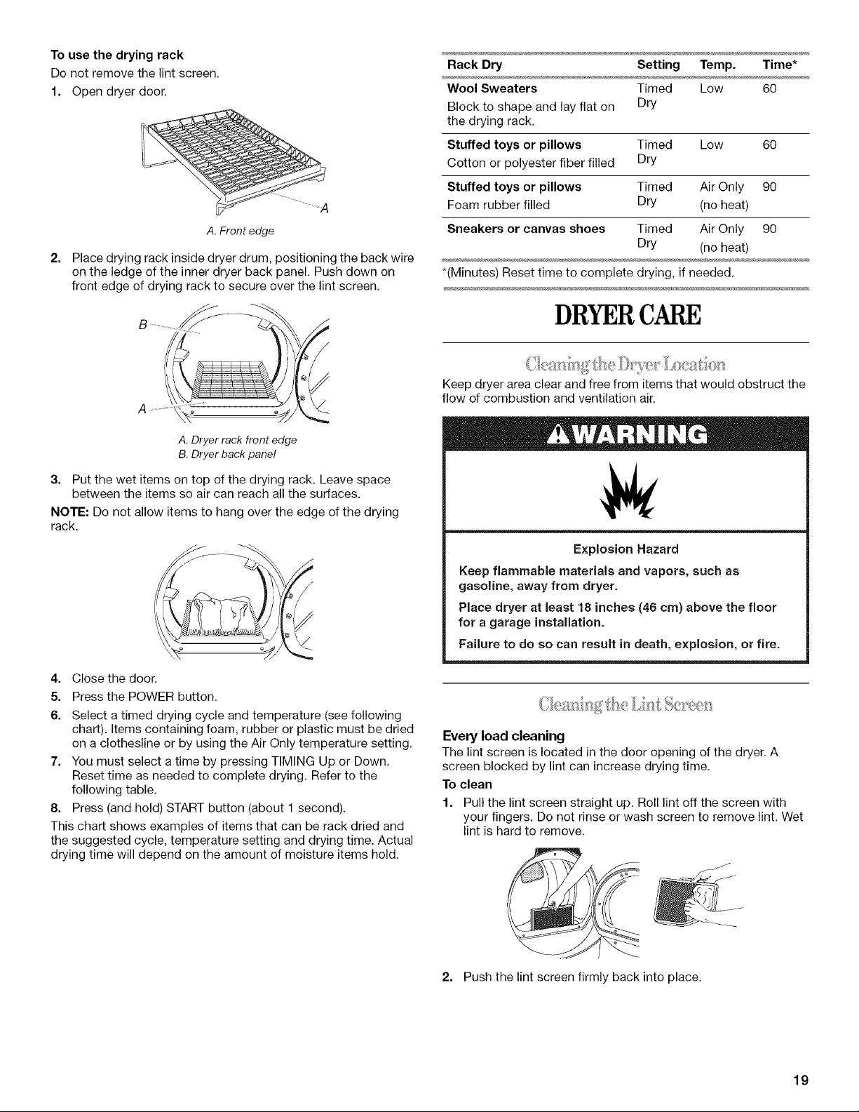
End of Cycle Signal
The End of Cycle Signal produces an audible sound when the
drying cycle is finished. Promptly removing clothes at the end of
the cycle reduces wrinkling.
ON
ENDOF I
CYCLESIGNALI
Hold3secondsto,,I
Lock/UnlockControl
Press and release the END OF CYCLE SIGNAL to turn off the
signal.
Hold the END OF CYCLE SIGNAL for 3 seconds to lock or unlock
this control.
NOTE: When the WRINKLE SHIELD TM feature is selected and the
End of Cycle Signal is on, an audible sound will be emitted every
5 minutes until the clothes are removed, or the WRINKLE
SHIELD TM feature is finished.
You can change Auto Cycles, Timed Cycles, Modifiers and
Options anytime before pressing Start.
• Three short tones sound if an unavailable combination is
selected. The last selection will not be accepted.
Changing Cycles after pressing Start
1. Press STOP twice. This ends the current cycle.
2. Select the desired cycle and options.
3. Press and hold START.The dryer starts at the beginning of
the new cycle.
NOTE: If you do not press Start within 5 minutes of selecting the
cycle, the dryer automatically shuts off.
Changing Modifiers and Options after pressing Start
You can change a Modifier or Option anytime before the selected
Modifier or Option begins.
1. Press STOP once.
2. Select the new Modifier and/or Option.
3. Press and hold START to continue the cycle.
NOTE: If you happen to press Stop twice, the program clears and
your dryer shuts down. Restart the selection process.
*Reset time to complete drying, if needed.
When using Air Only
• Check that coverings are securely stitched.
• Shake and fluff pillows by hand periodically during the cycle.
• Dry item completely. Foam rubber pillows are slow to dry.
NOTE: Auto Cycles are not available when you are using the Air
Only setting.
18
Use the Drying Rack to dry items such as sweaters and pillows
without tumbling. The drum turns, but the drying rack does not
move.
If your model does not have a drying rack, you may be able to
purchase one for your model. To find out whether your model
allows drying rack usage and for more information on ordering,
please refer to the front page of the manual or contact the dealer
from whom you purchased your dryer.
NOTE: The drying rack must be removed for normal tumbling. Do
not use the automatic cycle with the drying rack.
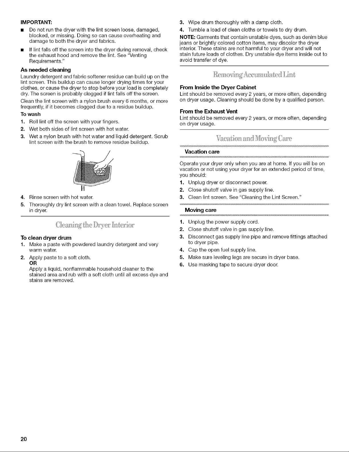
To use the drying rack
Do not remove the lint screen.
1. Open dryer door.
A. Front edge
2. Place drying rack inside dryer drum, positioning the back wire
on the ledge of the inner dryer back panel. Push down on
front edge of drying rack to secure over the lint screen.
A. Dryer rack front edge
B. Dryer back panel
Rack Dry Setting Temp. Time*
Wool Sweaters Timed Low 60
Block to shape and lay flat on Dry
the drying rack.
Stuffed toys or pillows Timed Low 60
Cotton or polyester fiber filled Dry
Stuffed toys or pillows Timed Air Only 90
Foam rubber filled Dry (no heat)
Sneakers or canvas shoes Timed Air Only
Dry (no heat)
*(Minutes) Reset time to complete drying, if needed.
9O
DRYERCARE
Keep dryer area clear and free from items that would obstruct the
flow of combustion and ventilation air.
3. Put the wet items on top of the drying rack. Leave space
between the items so air can reach all the surfaces.
NOTE: Do not allow items to hang over the edge of the drying
rack.
4. Close the door.
5. Press the POWER button.
6.
Select a timed drying cycle and temperature (see following
chart). Items containing foam, rubber or plastic must be dried
on a clothesline or by using the Air Only temperature setting.
7. You must select a time by pressing TIMING Up or Down.
Reset time as needed to complete drying. Refer to the
following table.
8. Press (and hold) START button (about 1 second).
This chart shows examples of items that can be rack dried and
the suggested cycle, temperature setting and drying time. Actual
drying time will depend on the amount of moisture items hold.
Explosion Hazard
Keep flammable materials and vapors, such as
gasoline, away from dryer.
Place dryer at least 18 inches (46 cm) above the floor
for a garage installation.
Failure to do so can result in death, explosion, or fire.
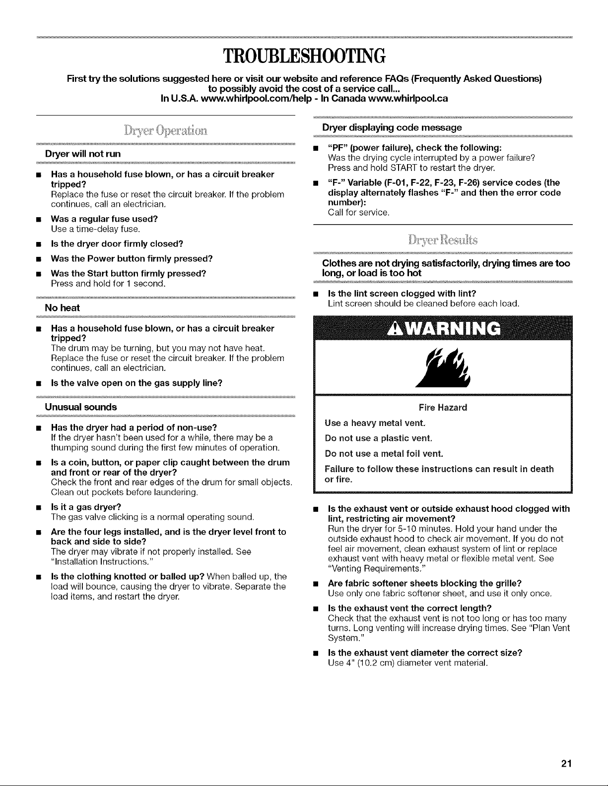
Every load cleaning
The lint screen is located in the door opening of the dryer. A
screen blocked by lint can increase drying time.
To clean
1. Pull the lint screen straight up. Roll lint off the screen with
your fingers. Do not rinse or wash screen to remove lint. Wet
lint is hard to remove.
2. Push the lint screen firmly back into place.
19
IMPORTANT:
• Do not run the dryer with the lint screen loose, damaged,
blocked, or missing. Doing so can cause overheating and
damage to both the dryer and fabrics.
• If lint falls off the screen into the dryer during removal, check
the exhaust hood and remove the lint. See "Venting
Requirements."
As needed cleaning
Laundry detergent and fabric softener residue can build up on the
lint screen. This buildup can cause longer drying times for your
clothes, or cause the dryer to stop before your load is completely
dry. The screen is probably clogged if lint falls off the screen.
Clean the lint screen with a nylon brush every 6 months, or more
frequently, if it becomes clogged due to a residue buildup.
To wash
1. Roll lint off the screen with your fingers.
2. Wet both sides of lint screen with hot water.
3. Wet a nylon brush with hot water and liquid detergent. Scrub
lint screen with the brush to remove residue buildup.
4. Rinse screen with hot water.
5. Thoroughly dry lint screen with a clean towel. Replace screen
in dryer.
3. Wipe drum thoroughly with a damp cloth.
4. Tumble a load of clean cloths or towels to dry drum.
NOTE: Garments that contain unstable dyes, such as denim blue
jeans or brightly colored cotton items, may discolor the dryer
interior. These stains are not harmful to your dryer and will not
stain future loads of clothes. Dry unstable dye items inside out to
avoid transfer of dye.
From Inside the Dryer Cabinet
Lint should be removed every 2 years, or more often, depending
on dryer usage. Cleaning should be done by a qualified person.
From the Exhaust Vent
Lint should be removed every 2 years, or more often, depending
on dryer usage.
Vacation care
Operate your dryer only when you are at home. If you will be on
vacation or not using your dryer for an extended period of time,
you should:
1. Unplug dryer or disconnect power.
2. Close shutoff valve in gas supply line.
3. Clean lint screen. See "Cleaning the Lint Screen."
Moving care
To clean dryer drum
1. Make a paste with powdered laundry detergent and very
warm water.
2=
Apply paste to a soft cloth.
OR
Apply a liquid, nonflammable household cleaner to the
stained area and rub with a soft cloth until all excess dye and
stains are removed.
1. Unplug the power supply cord.
2. Close shutoff valve in gas supply line.
3. Disconnect gas supply line pipe and remove fittings attached
to dryer pipe.
4. Cap the open fuel supply line.
5. Make sure leveling legs are secure in dryer base.
6. Use masking tape to secure dryer door.
20
TROUBLESHOOTING
Firsttry the solutions suggested here or visit our website and reference FAQs (Frequently Asked Questions)
In U.S.A. www.whirlpool.com/help - In Canada www.whirlpool.ca
to possibly avoid the cost of a service call...
Dryer displaying code message
Dryer will not run
• Has a household fuse blown, or has a circuit breaker
tripped?
Replace the fuse or reset the circuit breaker. Ifthe problem
continues, call an electrician.
• Was a regular fuse used?
Use a time-delay fuse.
• Is the dryer door firmly closed?
• Was the Power button firmly pressed?
• Was the Start button firmly pressed?
Press and hold for 1 second.
No heat
Has a household fuse blown, or has a circuit breaker
tripped?
The drum may be turning, but you may not have heat.
Replace the fuse or reset the circuit breaker. Ifthe problem
continues, call an electrician.
• Is the valve open on the gas supply line?
Unusual sounds
• Has the dryer had a period of non-use?
If the dryer hasn't been used for a while, there may be a
thumping sound during the first few minutes of operation.
Is a coin, button, or paper clip caught between the drum
and front or rear of the dryer?
Check the front and rear edges of the drum for small objects.
Clean out pockets before laundering.
Is it a gas dryer?
The gas valve clicking is a normal operating sound.
Are the four legs installed, and is the dryer level front to
back and side to side?
The dryer may vibrate if not properly installed. See
"Installation Instructions."
Is the clothing knotted or balled up? When balled up, the
load will bounce, causing the dryer to vibrate. Separate the
load items, and restart the dryer.
• "PF" (power failure), check the following:
Was the drying cycle interrupted by a power failure?
Press and hold START to restart the dryer.
"F-" Variable (F-01, F-22, F-23, F-26) service codes (the
display alternately flashes "F-" and then the error code
number):
Call for service.
Clothes are not drying satisfactorily, drying times are too
long, or load istoo hot
• Is the lint screen clogged with lint?
Lint screen should be cleaned before each load.
Fire Hazard
Use a heavy metal vent,
Do not use a plastic vent.
Do not use a metal foil vent.
Failure to follow these instructions can result in death
or fire.
Is the exhaust vent or outside exhaust hood clogged with
lint, restricting air movement?
Run the dryer for 5-10 minutes. Hold your hand under the
outside exhaust hood to check air movement. If you do not
feel air movement, clean exhaust system of lint or replace
exhaust vent with heavy metal or flexible metal vent. See
"Venting Requirements."
Are fabric softener sheets blocking the grille?
Use only one fabric softener sheet, and use it only once.
Is the exhaust vent the correct length?
Check that the exhaust vent is not too long or has too many
turns. Long venting will increase drying times. See "Plan Vent
System."
Is the exhaust vent diameter the correct size?
Use 4" (10.2 cm) diameter vent material.
21
Explosion Hazard
Keep flammable materials and vapors, such as
gasoline, away from dryer.
Place dryer at least 18 inches (46 cm) above the floor
for a garage installation.
Failure to do so can result in death, explosion, or fire.
Is the dryer located in a room with temperature below
45°F (7°C)?
Proper operation of dryer cycles requires temperatures above
45°F (7°C).
Is the dryer located in a closet?
Closet doors must have ventilation openings at the top and
bottom of the door. The front of the dryer requires a minimum
of 1" (2.5 cm) of airspace, and, for most installations, the rear
of the dryer requires 5" (12.7 cm). See "Installation
Instructions."
Has the Air Only temperature setting been selected?
Select the right temperature for the types of garments being
dried. See "Additional Features."
Is the load too large and heavy to dry quickly?
Separate the load to tumble freely.
Cycle time too short
Excessive Weight Hazard
Use two or more people to move and install dryer.
Failure to do so can result in back or other injury.
• Is the automatic cycle ending early?
The load may not be contacting the sensor strips. Level the
dryer.
Change the dryness level setting on Auto Cycles. Increasing
or decreasing the dryness level will change the amount of
drying time in a cycle.
Do not use a dryer rack with an Auto Cycle.
Lint on load
• Is the lint screen clogged?
Clean lint screen. Check for air movement.
Stains on load or drum
• Was dryer fabric softener properly used?
Add dryer fabric softener sheets at the beginning of the cycle.
Fabric softener sheets added to a partially dried load can
stain your garments.
Drum stains are caused by dyes in clothing (usually blue
jeans). This will not transfer to other clothing.
Loads are wrinkled
• Was the load removed from dryer at the end of the cycle?
• Was the dryer overloaded? Dry smaller loads that can
tumble freely.
Odors
• Have you recently been painting, staining or varnishing in
the area where your dryer is located?
If so, ventilate the area. When the odors or fumes are gone
from the area, rewash and dry the clothing.
22
ASSISTANCEORSERVICE
Before calling for assistance or service, please check
"Troubleshooting." It may save you the cost of a service call. If
you still need help, follow the instructions below.
When calling, please know the purchase date and the complete
model and serial number of your appliance. This information will
help us to better respond to your request.
If you need replacement parts
If you need to order replacement parts, we recommend that you
only use FSP®factory specified parts. These parts will fit right
and work right because they are made with the same precision
used to build every new WHIRLPOOL ®appliance.
To locate FSP®replacement parts in your area:
In the U.S.A., call the Customer eXperience Center at
1-800-253-1301, or your nearest designated service center.
In Canada, call 1-800-807-6777, or your nearest designated
service center.
Call the Whirlpool Customer eXperience Center toll free:
1-800-253-1301 or visit us at www.whirlpool.com.
Our consultants provide assistance with:
• Features and specifications on our full line of appliances.
• Installation information.
• Use and maintenance procedures.
• Accessory and repair parts sales.
• Specialized customer assistance (Spanish speaking, hearing
impaired, limited vision, etc.).
Referrals to local dealers, repair parts distributors, and
service companies. Whirlpool designated service technicians
are trained to fulfill the product warranty and provide after-
warranty service, anywhere in the United States.
To locate the Whirlpool designated service company in your
area, you can also look in your telephone directory Yellow
Pages.
For further assistance
If you need further assistance, you can write to Whirlpool
Corporation with any questions or concerns at:
Whirlpool Brand Home Appliances
Customer experience Center
553 Benson Road
Benton Harbor, M149022-2692
Please include a daytime phone number in your correspondence.
Accessories U.S.A.
To order accessories, call the Whirlpool Customer eXperience
Center toll free at 1-800-442-9991 and follow the menu prompts.
Or visit our website at www.whirlpool.com.
Call the Whirlpool Canada LP Customer Interaction Centre toll
free: 1-800-807-6777 or visit us at www.whirlpool.ca.
Our consultants provide assistance with:
• Use and maintenance procedures
• Accessory and repair parts sales
• Features and specifications on our full line of appliances
• Referrals to local dealers, repair parts distributors, and
service companies. Whirlpool Canada LP designated service
technicians are trained to fulfill the product warranty and
provide after-warranty service anywhere in Canada.
For further assistance
If you need further assistance, you can write to Whirlpool Canada
LP with any questions or concerns at:
Customer Interaction Centre
Whirlpool Canada LP
1901 Minnesota Court
Mississauga, Ontario L5N 3A7
Please include a daytime phone number in your correspondence.
ACCESSORIES
Enhance your dryer with these premium accessories. For more
high-quality items or to order, call 1-800-901-2042, or visit us at
w_rw.whirlpool.com/accessories. In Canada, call
1-800-807-6777, or visit us at www.whirlpoolparts.ca.
Part Number Accessory
20-48KITRC 4 ft (1.2 m) gas line dryer connector
installation kit
PT220L 4 ft (1.2 m) dryer cord, 3-wire, 30 amp
PT400L 4 ft (1.2 m) dryer cord, 4-wire, 30 amp
PT600L 6 ft (1.8 cm) dryer cord, 4-wire, 30 amp
4210463 Dryer vent lint brush
31682 All-purpose appliance cleaner
1903WH Laundry supply storage cart
8576846A LP gas conversion kit
W10121663A Dryer rack
8572546 Stack kit
23

WHIRLPOOLCORPORATIONMAJORAPPLIANCEWARRANTY
ONE YEAR LIMITED WARRANTY
For one year from the date of purchase, when this major appliance is operated and maintained according to instructions attached to or
furnished with the product, Whirlpool Corporation or Whirlpool Canada LP (hereafter "Whirlpool") will pay for Factory Specified Parts
and repair labor to correct defects in materials or workmanship. Service must be provided by a Whirlpool designated service company.
This limited warranty applies only when the major appliance is used in the country in which it was purchased.
ITEMS WHIRLPOOL WILL NOT PAY FOR
1. Service calls to correct the installation of your major appliance, to instruct you how to use your major appliance, to replace or repair
house fuses or to correct house wiring or plumbing.
2. Service calls to repair or replace appliance light bulbs, air filters or water filters. Those consumable parts are excluded from warranty
coverage.
3. Repairs when your major appliance is used for other than normal, single-family household use.
4. Damage resulting from accident, alteration, misuse, abuse, fire, flood, acts of God, improper installation, installation not in
accordance with electrical or plumbing codes, or use of products not approved by Whirlpool.
5. Any food loss due to refrigerator or freezer product failures.
6. Replacement parts or repair labor costs for units operated outside the United States or Canada.
7. Pickup and delivery. This major appliance is designed to be repaired in the home.
8. Repairs to parts or systems resulting from unauthorized modifications made to the appliance.
9. Expenses for travel and transportation for product service in remote locations.
10. The removal and reinstallation of your appliance if it is installed in an inaccessible location or is not installed in accordance with
published installation instructions.
11. Replacement parts or repair labor costs when the major appliance is used in a country other than the country in which it was
purchased.
DISCLAIMER OF IMPLIED WARRANTIES; LIMITATION OF REMEDIES
CUSTOMER'S SOLE AND EXCLUSIVE REMEDY UNDER THIS LIMITED WARRANTY SHALL BE PRODUCT REPAIR AS PROVIDED
HEREIN. IMPLIED WARRANTIES, INCLUDING WARRANTIES OF MERCHANTABILITY OR FITNESS FOR A PARTICULAR PURPOSE,
ARE LIMITED TO ONE YEAR OR THE SHORTEST PERIOD ALLOWED BY LAW. WHIRLPOOL SHALL NOT BE LIABLE FOR
INCIDENTAL OR CONSEQUENTIAL DAMAGES. SOME STATES AND PROVINCES DO NOT ALLOW THE EXCLUSION OR LIMITATION
OF INCIDENTAL OR CONSEQUENTIAL DAMAGES, OR LIMITATIONS ON THE DURATION OF IMPLIED WARRANTIES OF
MERCHANTABILITY OR FITNESS, SO THESE EXCLUSIONS OR LIMITATIONS MAY NOT APPLY TO YOU. THIS WARRANTY GIVES
YOU SPECIFIC LEGAL RIGHTS AND YOU MAY ALSO HAVE OTHER RIGHTS, WHICH VARY FROM STATETO STATE OR PROVINCE
TO PROVINCE.
Outside the 50 United States and Canada, this warranty does not apply. Contact your authorized Whirlpool dealer to determine if
another warranty applies.
If you need service, first see the "Troubleshooting" section of the Use & Care Guide. After checking "Troubleshooting," additional help
can be found by checking the "Assistance or Service" section or by calling Whirlpool. Inthe U.S.A., call f-800-253-1301. In Canada,
call 1-800-807-6777. 12/o5
Keep this book and your sales slip together for future
reference. You must provide proof of purchase or installation
date for in-warranty service.
Write down the following information about your major appliance
to better help you obtain assistance or service ifyou ever need it.
You will need to know your complete model number and serial
number. You can find this information on the model and serial
number label located on the product.
Dealer name
Address
Phone number
Model number
Serial number
Purchase date
24

SECURITEDELASECHEUSE
Votre s_curit_ et celle des autres est tres importante.
Nous donnons de nombreux messages de securite importants dans ce manuel et sur votre appareil menager. Assurez-vous de
toujours lire tousles messages de securite et de vous y conformer.
Ce symbole d'alerte de securite vous signale les dangers potentiels de deces et de blessures graves & vous
et a d'autres.
Voici le symbole d'alerte de securite.
Tousles messages de securite suivront le symbole d'alerte de securite et le mot "DANGER" ou
"AVERTISSEMENT". Ces roots signifient :
Risque possible de deces ou de blessure grave si vous ne
suivez pas immediatement lee instructions.
Risque possible de deces ou de blessure grave si vous
ne euivez pas lee instructions.
Tousles messages de securite vous diront quel est le danger potentiel et vous disent comment reduire le risque de blessure et
ce qui peut se produire en cas de non-respect des instructions.
AVERTISSEMENT : Pour votre s_curit_, les renseignements dans ce manuel doivent
_tre observes pour r_duire au minimum les risques d'incendie ou d'explosion ou pour
_viter des dommages au produit, des blessures ou un d_c_s.
- Ne pas entreposer ou utiliser de I'essence ou d'autres vapeurs ou liquides
inflammables a proximit_ de cet appareil ou de tout autre appareil _lectrom_nager.
- QUE FAIRE DANS LE CAS D'UNE ODEUR DE GAZ :
• Ne pas tenter d'allumer un appareil.
• Ne pas toucher a un commutateur _lectrique; ne pas utiliser le t_l_phone se trouvant
sur les lieux.
• I_vacuer tous les gens de la piece, de I'_difice ou du quartier.
• Appeler imm_diatement le fournisseur de gaz d'un t_l_phone voisin. Suivre ses
instructions.
• A d_faut de joindre votre fournisseur de gaz, appeler les pompiers.
- L'installation et I'entretien doivent _tre effectu_s par un installateur qualifi_, une
agence de service ou le fournisseur de gaz.
25
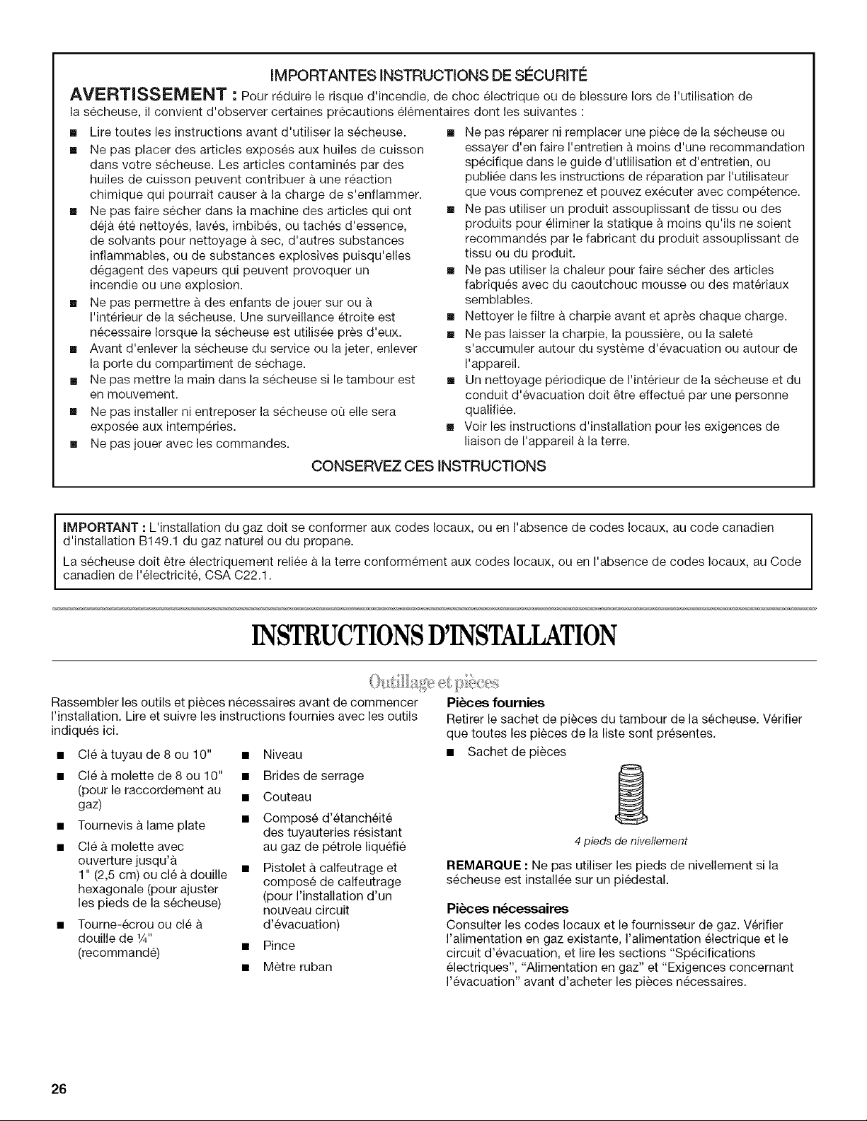
IM PORTANTES INSTRUCTIONS DE SECU RIT¢:
AVERTISSEMENT : Pour reduire le risque d'incendie, de choc electrique ou de blessure Iors de I'utilisation de
la secheuse, il convient d'observer certaines precautions elementaires dont les suivantes :
• Lire toutes les instructions avant d'utiliser la secheuse. • Ne pas reparer ni remplacer une piece de la secheuse ou
• Ne pas placer des articles exposes aux huiles de cuisson
dans votre secheuse. Les articles contamines par des
huiles de cuisson peuvent contribuer & une reaction
chimique qui pourrait causer a la charge de s'enflammer.
• Ne pas faire secher darts la machine des articles qui ont
deja et6 nettoyes, laves, imbibes, ou taches d'essence,
de solvants pour nettoyage a sec, d'autres substances
inflammables, ou de substances explosives puisqu'elles
degagent des vapeurs qui peuvent provoquer un
incendie ou une explosion.
• Ne pas permettre a des enfants de jouer sur ou
I'interieur de la secheuse. Une surveillance etroite est
necessaire Iorsque la secheuse est utilisee pres d'eux.
• Avant d'enlever la secheuse du service ou la jeter, enlever
la porte du compartiment de sechage.
• Ne pas mettre la main darts la secheuse si le tambour est
en mouvement.
• Ne pas installer ni entreposer la secheuse oQ elle sera
exposee aux intemperies.
• Ne pas jouer avec les commandes.
CONSERVEZ CES iNSTRUCTiONS
essayer d'en faire I'entretien a moins d'une recommandation
specifique dans le guide d'utlilisation et d'entretien, ou
publiee dans les instructions de reparation par I'utilisateur
que vous comprenez et pouvez executer avec competence.
• Ne pas utiliser un produit assouplissant de tissu ou des
produits pour eliminer la statique a moins qu'ils ne soient
recommandes par le fabricant du produit assouplissant de
tissu ou du produit.
• Ne pas utiliser la chaleur pour faire secher des articles
fabriques avec du caoutchouc mousse ou des materiaux
semblables.
• Nettoyer le filtre a charpie avant et apres chaque charge.
• Ne pas laisser la charpie, la poussiere, ou la salete
s'accumuler autour du systeme d'evacuation ou autour de
I'appareil.
• Un nettoyage periodique de I'interieur de la secheuse et du
conduit d'evacuation dolt _tre effectue par une personne
qualifiee.
[] Voir les instructions d'installation pour les exigences de
liaison de I'appareil a la terre.
iMPORTANT : L'installation du gaz dolt se conformer aux codes Iocaux, ou en I'absence de codes Iocaux, au code canadien
d'installation B149.1 du gaz naturel ou du propane.
La secheuse dolt _tre electriquement reliee & la terre conformement aux codes Iocaux, ou en I'absence de codes Iocaux, au Code
canadien de I'electricit6, CSA C22.1.
INSTRUCTIONSD'INSTALLATION
Rassembler les outils et pieces necessaires avant de commencer
I'installation. Lire et suivre les instructions fournies avec les outils
indiques ici.
• Cle&tuyaude8oul0" • Niveau
Cle & molette de 8 ou 10" •
(pour le raccordement au
gaz) •
Tournevis &lame plate •
Cle & molette avec
ouverture jusqu'a
1" (2,5 cm) ou cle & douille
hexagonale (pour ajuster
les pieds de la secheuse)
Tourne-ecrou ou cle
douille de 1/4"
(recommande)
Brides de serrage
Couteau
Compose d'etancheite
des tuyauteries resistant
au gaz de petrole liquefie
Pistolet &calfeutrage et
compose de calfeutrage
(pour I'installation d'un
nouveau circuit
d'evacuation)
Pince
Metre ruban
Pi_ces fournies
Retirer le sachet de pieces du tambour de la secheuse. Verifier
que toutes les pieces de la liste sont presentes.
• Sachet de pieces
4 pieds de nivellement
REMARQUE : Ne pas utiliser les pieds de nivellement si la
secheuse est installee sur un piedestal.
Pi_ces n_cessaires
Consulter les codes Iocaux et le fournisseur de gaz. Verifier
I'alimentation en gaz existante, I'alimentation electrique et le
circuit d'evacuation, et life les sections "Specifications
electriques", "Alimentation en gaz" et "Exigences concernant
I'evacuation" avant d'acheter les pieces necessaires.
26
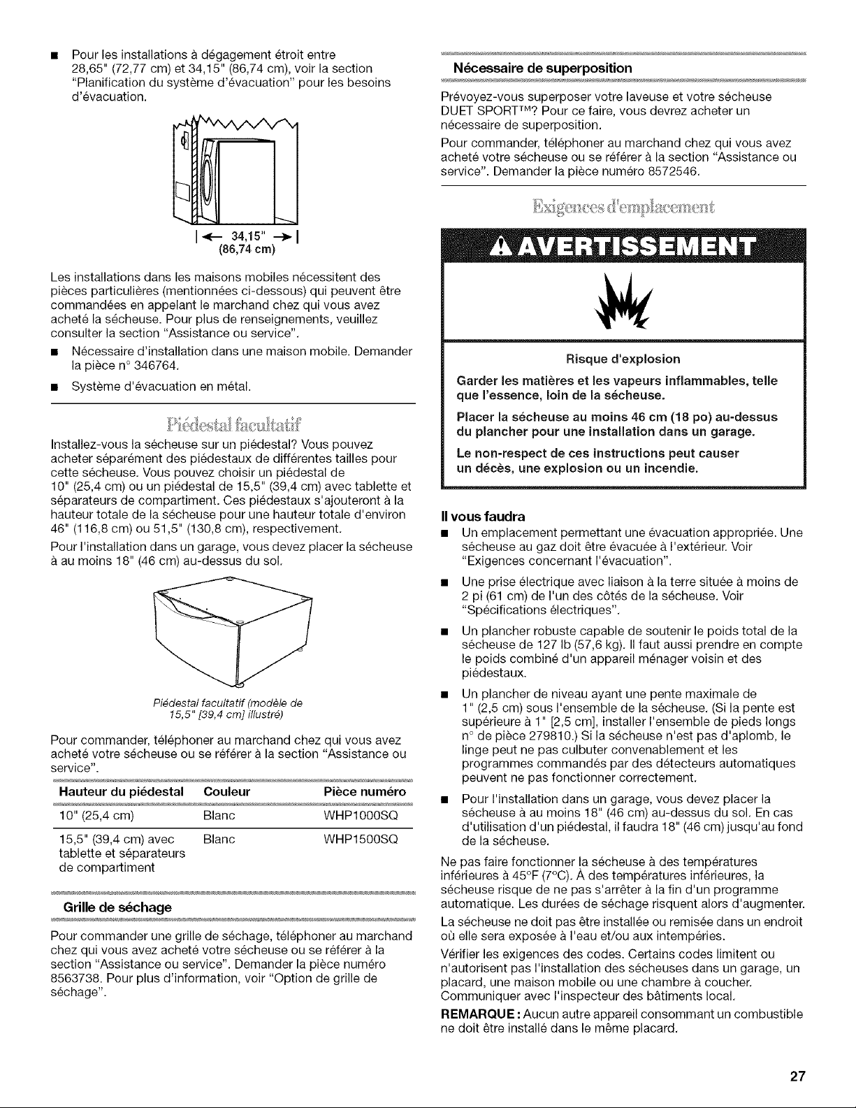
Pour les installations a degagement etroit entre
28,65" (72,77 cm) et 34,15" (86,74 cm), voir la section
"Planification du syst_me d'evacuation" pour les besoins
d'evacuation.
I*- 34,15"
(86,74 cm)
Les installations dans les maisons mobiles necessitent des
pieces particulieres (mentionnees ci-dessous) qui peuvent _tre
commandees en appelant le marchand chez qui vous avez
achete la secheuse. Pour plus de renseignements, veuillez
consulter la section "Assistance ou service".
• Necessaire d'installation dans une maison mobile. Demander
la piece n° 346764.
• Systeme d'evacuation en metal.
Installez-vous la secheuse sur un piedestal? Vous pouvez
acheter separement des piedestaux de differentes tallies pour
cette secheuse. Vous pouvez choisir un piedestal de
10" (25,4 cm) ou un piedestal de 15,5" (39,4 cm) avec tablette et
separateurs de compartiment. Ces piedestaux s'ajouteront a la
hauteur totale de la secheuse pour une hauteur totale d'environ
46" (116,8 cm) ou 51,5" (130,8 cm), respectivement.
Pour I'installation dans un garage, vous devez placer la secheuse
au moins 18" (46 cm) au-dessus du sol.
Pi_destal facultatif (rnodele de
15,5" [39,4 cm] illustr_)
Pour commander, telephoner au marchand chez qui vous avez
achete votre secheuse ou se rderer a la section "Assistance ou
service".
Hauteur du pi_destal Couleur Piece numero
10" (25,4 cm) Blanc WHP1000SQ
15,5" (39,4 cm) avec Blanc
tablette et separateurs
de compartiment
Grille de s_chage
Pour commander une grille de sechage, tel6phoner au marchand
chez qui vous avez achete votre secheuse ou se rderer a la
section "Assistance ou service". Demander la piece numero
8563738. Pour plus d'information, voir "Option de grille de
sechage".
WHP1500SQ
N_cessaire de superposition
Prevoyez-vous superposer votre laveuse et votre secheuse
DUET SPORTTM? Pour ce faire, vous devrez acheter un
necessaire de superposition.
Pour commander, telephoner au marchand chez qui vous avez
achete votre secheuse ou se referer a la section "Assistance ou
service". Demander la piece numero 8572546.
Risque d'explosion
Garder les matieres et les vapeurs inflammables, telle
que I'essence, loin de la s_cheuse.
Placer la secheuse au moins 46 cm (18 pc) au-dessus
du plancher pour une installation darts un garage.
Le non-respect de ces instructions peut causer
un d_cbs, une explosion ou un incendie.
II vous faudra
• Un emplacement permettant une evacuation appropriee. Une
secheuse au gaz dolt _tre evacuee a I'exterieur. Voir
"Exigences concernant I'evacuation'.
• Une prise electrique avec liaison a la terre situee a moins de
2 pi (61 cm) de I'un des c6tes de la secheuse. Voir
"Specifications electriques".
Un plancher robuste capable de soutenir le poids total de la
secheuse de 127 Ib (57,6 kg). II faut aussi prendre en compte
le poids combine d'un appareil menager voisin et des
piedestaux.
Un plancher de niveau ayant une pente maximale de
1" (2,5 cm) sous I'ensemble de la secheuse. (Si la pente est
superieure & 1" [2,5 cm], installer I'ensemble de pieds longs
n° de piece 279810.) Si la secheuse n'est pas d'aplomb, le
linge peut ne pas culbuter convenablement et les
programmes commandes par des detecteurs automatiques
peuvent ne pas fonctionner correctement.
Pour I'installation dans un garage, vous devez placer la
secheuse a au moins 18" (46 cm) au-dessus du sol. En cas
d'utilisation d'un piedestal, il faudra 18" (46 cm) jusqu'au fond
de la secheuse.
Ne pas faire fonctionner la secheuse & des temperatures
inferieures a 45°F (7°C). A des temperatures inferieures, la
secheuse risque de ne pas s'arr_ter a la fin d'un programme
automatique. Les durees de sechage risquent alors d'augmenter.
La secheuse nedolt pas _tre installee ou remisee dans un endroit
0(4elle sera exposee & I'eau et/ou aux intemperies.
Verifier les exigences des codes. Certains codes limitent ou
n'autorisent pas I'installation des secheuses dans un garage, un
placard, une maison mobile ou une chambre &coucher.
Communiquer avec I'inspecteur des b&timents local.
REMARQUE : Aucun autre appareil consommant un combustible
ne dolt _tre installe dans le m_me placard.
27
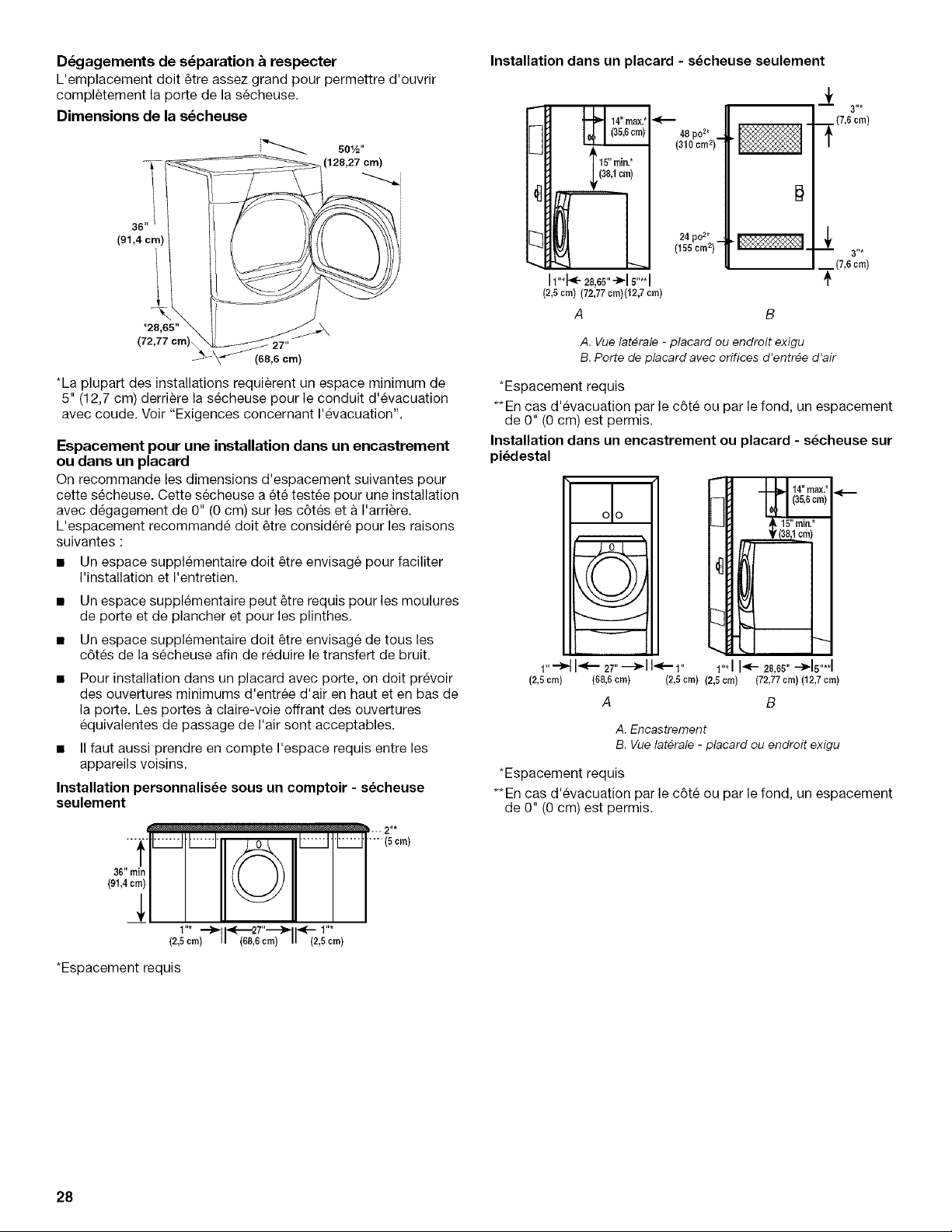
DL_jagements de s_paration & respecter
L'emplacementdolt _tre assezgrand pour permettre d'ouvrir
completement laporte de la secheuse.
Dimensions de la s_cheuse
501/2''
(126,27 cm)
Installation dans un placard - s_cheuse seulement
A
3"*
.__(7,6cm)
38 _l
(91,4 cm)
*28,65"
(72,77 cm), 27"
(68,6 cm)
*La plupart des installations requierent un espace minimum de
5" (12,7 cm) derriere la s_cheuse pour le conduit d'evacuation
avec coude. Voir "Exigences concernant I'evacuation".
Espacement pour une installation dans un encastrement
ou dans un placard
On recommande les dimensions d'espacement suivantes pour
cette secheuse. Cette secheuse a ete testee pour une installation
avec degagement de 0" (0 cm) sur les c6tes et & I'arriere.
L'espacement recommande dolt 6tre consider6 pour les raisons
suivantes :
• Un espace supplementaire dolt _tre envisage pour faciliter
I'installation et I'entretien.
• Un espace supplementaire peut _tre requis pour les moulures
de porte et de plancher et pour les plinthes.
• Un espace supplementaire dolt _tre envisage de tousles
c6tes de la secheuse afin de reduire le transfert de bruit.
Pour installation dans un placard avec porte, on dolt prevoir
des ouvertures minimums d'entree d'air en haut et en bas de
la porte. Les portes a claire-vole offrant des ouvertures
equivalentes de passage de I'air sont acceptables.
• II faut aussi prendre en compte I'espace requis entre les
appareils voisins.
Installation personnalis_e sous un comptoir - s_cheuse
seulement
., 2,1.
24 po2* .
(155cm2)
4,
3"*
-- (7,6 crn)
I1"'1<-28,65""_1s"**l
{2,5cm) {72,77crn)(12,7 crn)
A
A. Vue lat_rale - placard ou endroit exigu
B. Porte de placard avec orifices d'entr_e d'air
*Espacement requis
**En cas d'evacuation par le c6te ou par le fond, un espacement
de 0" (0 cm) est permis.
Installation dans un encastrement ou placard - s_cheuse sur
pi_destal
II °
1"-'*-tI'*- 2T'---._11<---1"
{2,5 cm) {68,6 cm) (2,5 cm) (2,5 cm)
A
A. Encastrement
B. Vue lat_rale - placard ou endroit exigu
*Espacement requis
**En cas d'evacuation par le c6te ou par le fond, un espacement
de 0" (0 cm) est permis.
1"*11_-28,6_"-_15"**1
(72,77crn) {12,7cm)
B
....t ll I'''°m'
3°"m,n I
4;II I1 11II
*Espacement requis
28
1"* _ "_-_27"_ _-- 1"*
25crn 686cm 25crn
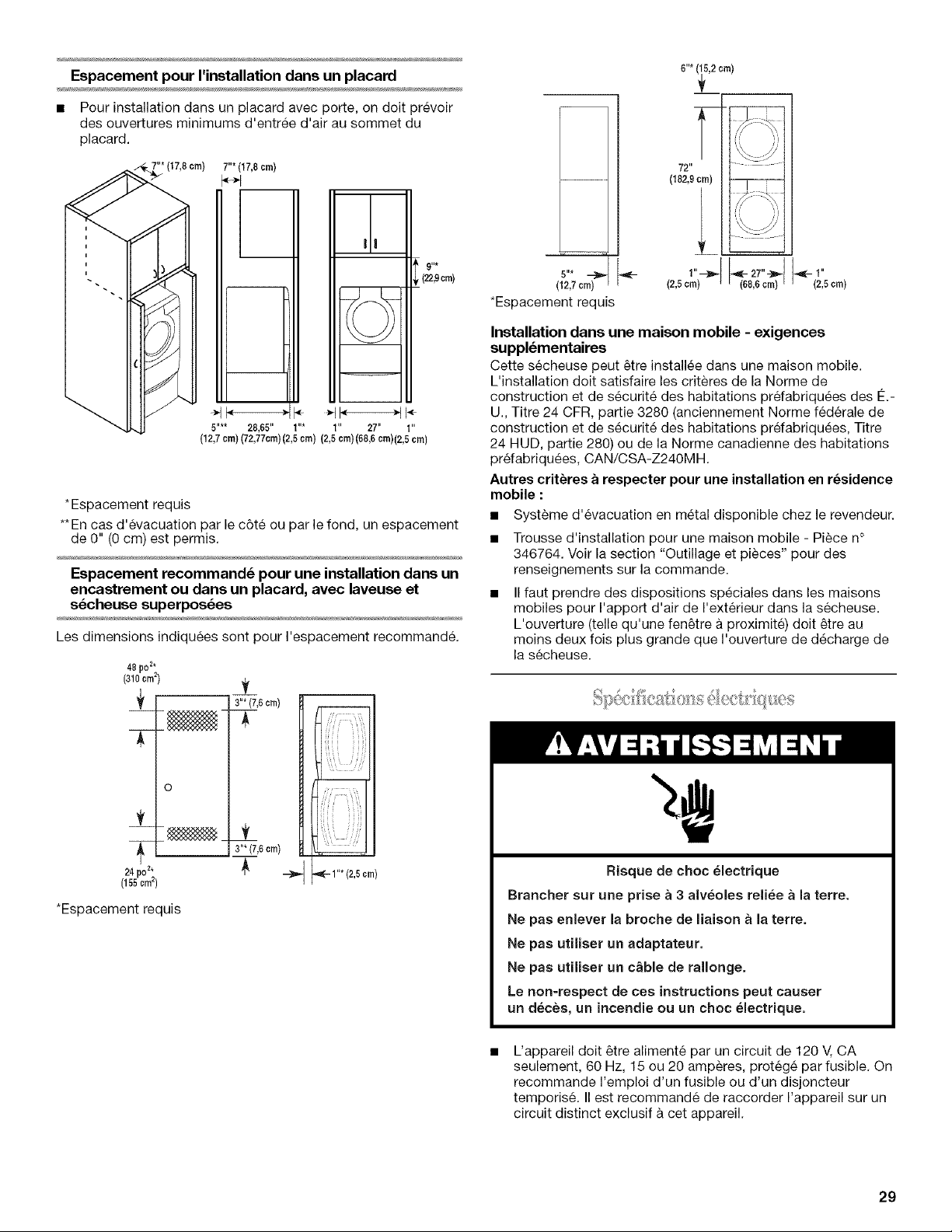
Espacement pour I'installation dans un placard
• Pour installation dans un placard avec porte, on dolt prevoir
des ouvertures minimums d'entree d'air au sommet du
placard.
" , _"_,_17,6crn)
72"
(182,9crn)
9"*
(22,9crn)
m) 5"** 28,65" 1"*
(12,7 crn) (72,77crn) (2,5 crn) (2,5 crn) (68,6 crn)(2,5 crn)
*Espacement requis
**En cas d'evacuation par le c6te ou par le fond, un espacement
de 0" (0 cm) est permis.
Espacement recommand_ pour une installation dans un
encastrement ou dans un placard, avec laveuse et
s_cheuse superpos_es
Les dimensions indiquees sont pour I'espacement recommand&
48 po2.
(310cm2) __
_f 3"* (7,6 cm)
6"* --_-
(12,7 cm)
_- 1"--_ _ 27"-_d
(2,5 crn) (68,6 crn) '
_- 1"
(2,6cm)
*Espacement requis
Installation dans une maison mobile - exigences
suppl_mentaires
Cette secheuse peut _tre installee dans une maison mobile.
L'installation dolt satisfaire les criteres de la Norme de
construction et de securite des habitations prefabriquees des E.-
U., Titre 24 CFR, partie 3280 (anciennement Norme fed6rale de
construction et de securite des habitations prefabriquees, Titre
24 HUD, partie 280) ou de la Norme canadienne des habitations
prefabriquees, CAN/CSA-Z240MH.
Autres crit_res a respecter pour une installation en r_sidence
mobile :
• Systeme d'evacuation en metal disponible chez le revendeur.
Trousse d'installation pour une maison mobile - Piece n°
346764. Voir la section "Outillage et pieces" pour des
renseignements sur la commande.
IIfaut prendre des dispositions speciales dans les maisons
mobiles pour I'apport d'air de I'exterieur dans la secheuse.
L'ouverture (telle qu'une fen_tre a proximite) dolt 6tre au
moins deux fois plus grande que I'ouverture de decharge de
la secheuse.
0
24 po 2.
(150crn2)
*Espacement requis
3"* (7,6 crn)
m
1"* (2,5 crn}
Risque de choc electrique
Brancher sur une prise a 3 alveoles reliee a la terre.
Ne pas enlever la broche de liaison a la terre.
Ne pas utiliser un adaptateur.
Ne pas utiliser un c&ble de rallonge.
Le non-respect de ces instructions peut causer
un deces, un incendie ou un choc electrique.
L'appareil dolt 6tre alimente par un circuit de 120 V, CA
seulement, 60 Hz, 15 ou 20 amperes, protege par fusible. On
recommande I'emploi d'un fusible ou d'un disjoncteur
temporis& II est recommande de raccorder I'appareil sur un
circuit distinct exclusif a cet appareil.
29
 Loading...