

Whirlpool WFG505M0BW0, WFG505M0BS3, WFG505M0BS0, WFG505M0BB0 Installation Guide
INSTALLATIONINSTRUCTIONS
30" (76.2 CM) FREESTANDINGGAS RANGES
INSTRUCTIONSD'INSTALLATIONDESCUISINIERESA GAZ
AUTOPORTANTESDE30" (76,2 CM)
TableofContents/Table des mati@res
RANGE SAFETY ............................................................................. 2
INSTALLATION REQUIREMENTS ............................................... 3
Tools and Parts............................................................................ 3
Location Requirements ............................................................... 4
Electrical Requirements ............................................................... 5
Gas Supply Requirements ........................................................... 6
INSTALLATION INSTRUCTIONS ................................................. 7
Unpack Range ............................................................................. 7
Install Anti-Tip Bracket ................................................................ 7
Make Gas Connection ................................................................. 8
Verify Anti-Tip Bracket Is Installed and Engaged ........................ 9
Level Range ............................................................................... 10
Electronic Ignition System ......................................................... 10
Complete Installation ................................................................. 12
GAS CONVERSIONS ................................................................... 12
LP Gas Conversion .................................................................... 12
Complete Conversion ................................................................ 14
Natural Gas Conversion ............................................................ 14
Complete Conversion ................................................................ 16
SI_CURITI_ DE LA CUISINII_RE ................................................... 17
EXIGENCES D'INSTALLATION ................................................... 18
Outillage et pieces ...................................................................... 18
Exigences d'emplacement ......................................................... 19
Specifications electriques .......................................................... 20
Specifications de I'alimentation en gaz ..................................... 21
INSTRUCTIONS D'INSTALLATION ............................................ 22
Deballage de la cuisiniere .......................................................... 22
Installation de la bride antibasculement .................................... 22
Raccordement au gaz................................................................ 23
Verifier que la bride antibasculement est
bien installee et engagee ........................................................... 24
Reglage de I'aplomb de la cuisiniere ......................................... 25
Systeme d'allumage electronique ............................................. 25
Achever I'installation .................................................................. 26
CONVERSIONS POUR CHANGEMENT DE GAZ ...................... 27
Conversion pour I'alimentation au propane .............................. 27
Terminer la conversion ............................................................... 29
Conversion pour I'alimentation au gaz naturel .......................... 30
Terminer la conversion ............................................................... 31
iMPORTANT:
Installer: Leave installation instructions with the homeowner.
Homeowner: Keep installation instructions for future reference.
iMPORTANT :
Installateur : Remettre les instructions d'installation au propri6taire.
Propri6taire : Conserver les instructions d'installation pour r6f6rence ult_rieure.
W10616596C
RANGESAFETY
Your safety and the safety of others are very important.
We have provided many important safety messages in this manual and on your appliance. Always read and obey all safety
messages.
This is the safety alert symbol.
This symbol alerts you to potential hazards that can kill or hurt you and others.
All safety messages will follow the safety alert symbol and either the word "DANGER" or "WARNING."
These words mean:
You can be killed or seriously injured if you don't immediately
follow instructions.
You can be killed or seriously injured if you don't follow
instructions.
All safety messages will tell you what the potential hazard is, tell you how to reduce the chance of injury, and tell you what can
happen if the instructions are not followed.
WARNING: If the information in this manual is not followed exactly, a fire or explosion
may result causing property damage, personal injury or death,
- Do not store or use gasoline or other flammable vapors and liquids in the vicinity of this
or any other appliance.
- WHAT TO DO IF YOU SMELL GAS:
• Do not try to light any appliance.
• Do not touch any electrical switch.
• Do not use any phone in your building.
• Immediately call your gas supplier from a neighbor's phone. Follow the gas supplier's
instructions.
• If you cannot reach your gas supplier, call the fire department.
- Installation and service must be performed by a qualified installer, service agency or
the gas supplier,
WARNING: Gas leaks cannot always be detected by smell.
Gas suppliers recommend that you use a gas detector approved by UL or CSA.
For more information, contact your gas supplier.
If a gas leak is detected, follow the "What to do if you smell gas" instructions.
iMPORTANT: Do not install a ventilation system that blows air downward toward this gas cooking appliance. This type of
ventilation system may cause ignition and combustion problems with this gas cooking appliance resulting in personal injury or
unintended operation.
2
In the State of Massachusetts, the following installation instructions apply:
• Installations and repairs must be performed by a qualified or licensed contractor, plumber, or gasfitter qualified or licensed by
the State of Massachusetts.
• If using a ball valve, it shall be a T-handle type.
• A flexible gas connector, when used, must not exceed 3 feet.
Tip Over Hazard
A child or adult can tip the range and be killed.
Install anti-tip bracket to floor or wall per installation instructions.
Slide range back so rear range foot is engaged in the slot of the anti-tip bracket.
Re-engage anti-tip bracket if range is moved.
Do not operate range without anti-tip bracket installed and engaged.
Failure to follow these instructions can result in death or serious burns to children and adults.
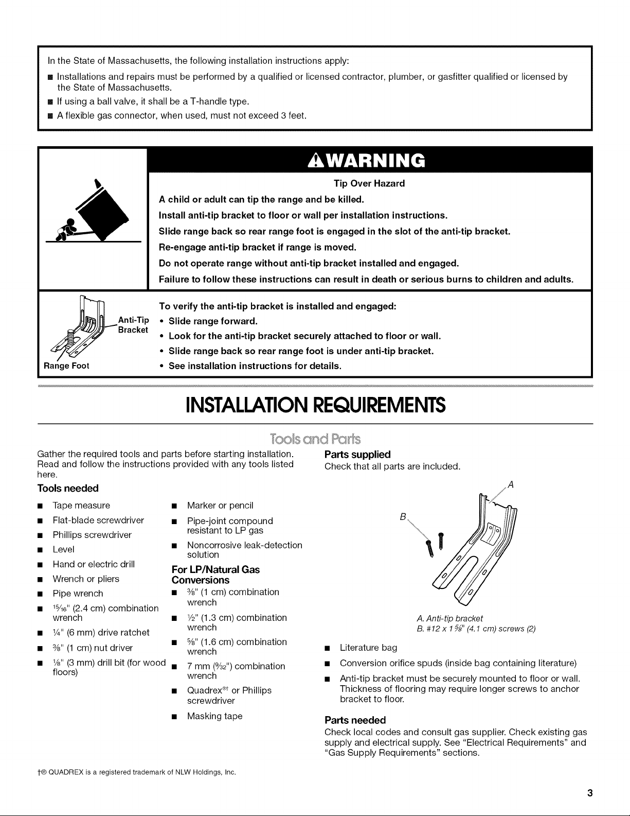
To verify the anti-tip bracket is installed and engaged:
Anti-Tip
Bracket
Range Foot
• Slide range forward.
• Look for the anti-tip bracket securely attached to floor or wall.
• Slide range back so rear range foot is under anti-tip bracket.
• See installation instructions for details.
INSTALLATIONREQUIREMENTS
Gather the required tools and parts before starting installation.
Read and follow the instructions provided with any tools listed
here.
Tools needed
• Tape measure • Marker or pencil
• Flat-blade screwdriver • Pipe-joint compound
• Phillips screwdriver resistant to LP gas
• Level • Noncorrosive leak-detection
• Hand or electric drill
• Wrench or pliers Conversions
• Pipe wrench • 3/8"(1 cm) combination
• ls/lS" (2.4 cm) combination
wrench • 1/2"(1.3 cm) combination
• 1¼,,(6 mm) drive ratchet
• 3/8"(1 cm) nut driver wrench
• 1/8"(3 mm) drill bit (for wood • 7 mm (%2")combination
floors) wrench
solution
For LP/Natural Gas
wrench
wrench
• 8/8"(1.6 cm) combination
• Quadrex ®tor Phillips
screwdriver
• Masking tape
Parts supplied
Check that all parts are included.
A
Y
B_\\\_ (//_
A. Anti-tip bracket
B. #12 x 1_" (4.1 cm) screws (2)
• Literature bag
• Conversion orifice spuds (inside bag containing literature)
• Anti-tip bracket must be securely mounted to floor or wall.
Thickness of flooring may require longer screws to anchor
bracket to floor.
Parts needed
Check local codes and consult gas supplier. Check existing gas
supply and electrical supply. See "Electrical Requirements" and
"Gas Supply Requirements" sections.
t® QUADREX is a registered trademark of NLW Holdings, Inc.
IMPORTANT: Observe all governing codes and ordinances. Do
not obstruct flow of combustion and ventilation air.
• It is the installer's responsibility to comply with installation
clearances specified on the model/serial rating plate. The
model/serial rating plate is located on the left side of the
bottom of the broiler.
;: In Canada, the installation of this range must conform with the
A. Model/serial rating plate location
• The range should be located for convenient use in the
kitchen.
Recessed installations must provide complete enclosure of
the sides and rear of the range.
To eliminate the risk of burns or fire by reaching over heated
surface units, cabinet storage space located above the
surface units should be avoided. If cabinet storage is to be
provided, the risk can be reduced by installing a range hood
that projects horizontally a minimum of 5" (12.7 cm) beyond
the bottom of the cabinets.
• All openings in the wall or floor where range is to be installed
must be sealed.
• Do not seal the range to the side cabinets.
• Cabinet opening dimensions that are shown must be used.
Given dimensions are minimum clearances.
• The anti-tip bracket must be installed. To install the anti-tip
bracket shipped with the range, see "Install Anti-Tip Bracket"
section.
• Grounded electrical supply is required. See "Electrical
Requirements" section.
• Proper gas supply connection must be available. See "Gas
Supply Requirements" section.
• Contact a qualified floor covering installer to check that the
floor covering can withstand at least 200°F (93°C).
• Use an insulated pad or 1¼,,(0.64 cm) plywood under range if
installing range over carpeting.
IMPORTANT: To avoid damage to your cabinets, check with your
builder or cabinet supplier to make sure that the materials used
will not discolor, delaminate or sustain other damage. This oven
has been designed in accordance with the requirements of UL
and CSA International and complies with the maximum allowable
wood cabinet temperatures of 194°F (90°C).
Mobile Home - Additional Installation Requirements
The installation of this range must conform to the Manufactured
Home Construction and Safety Standard, Title 24 CFR, Part 3280
(formerly the Federal Standard for Mobile Home Construction
and Safety, Title 24, HUD Part 280). When such standard is not
applicable, use the Standard for Manufactured Home
Installations, ANSI A225.1/NFPA 501A or with local codes.
current standards CAN/CSA-A240 - latest edition, or with local
codes.
Mobile home installations require:
• When this range is installed in a mobile home, it must be
secured to the floor during transit. Any method of securing
the range is adequate as long as it conforms to the standards
listed above.
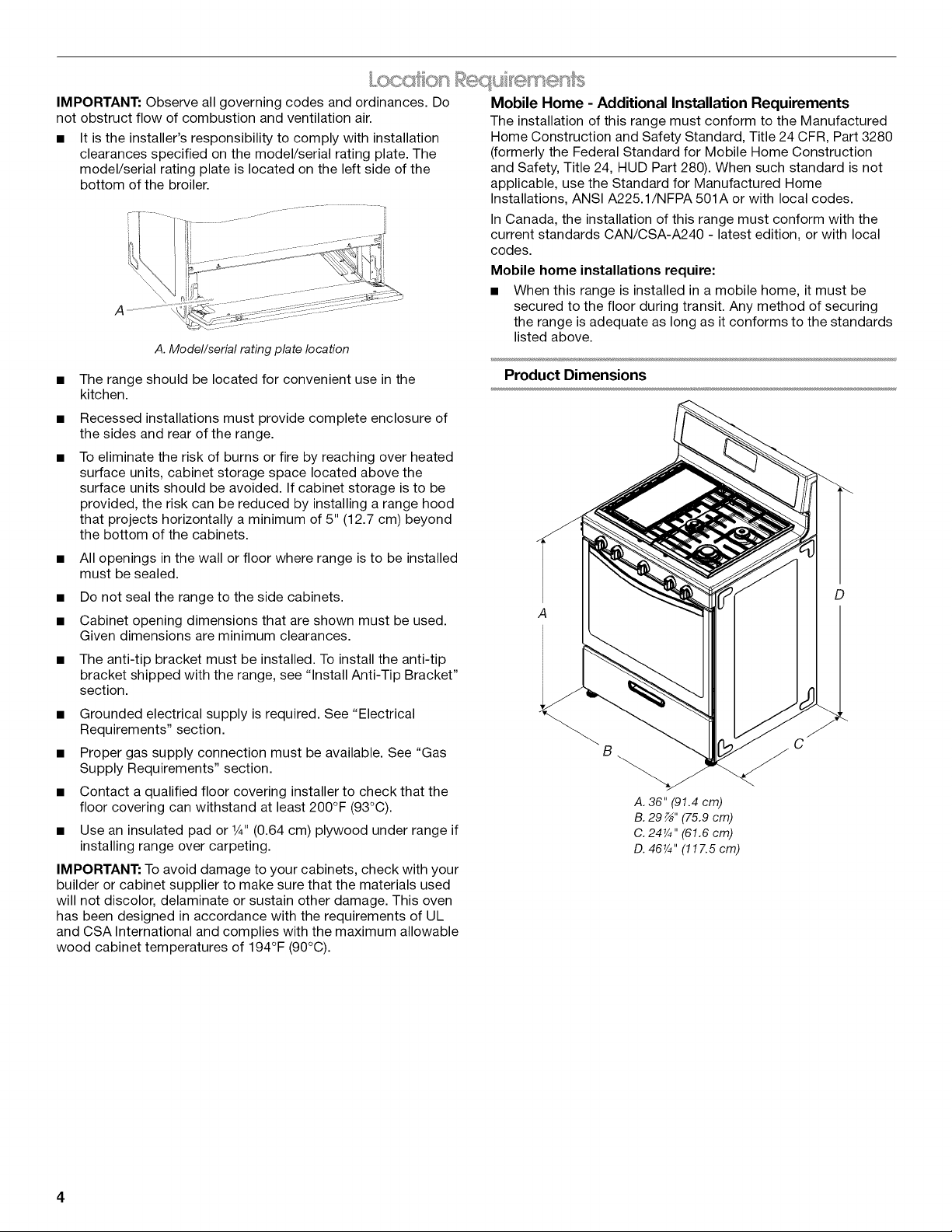
Product Dimensions
D
B
A. 36" (91.4 cm)
B. 29 z_,,(75.9 cm)
C. 24¼" (61.6 cm)
D. 46¼" (117.5 cm)
C
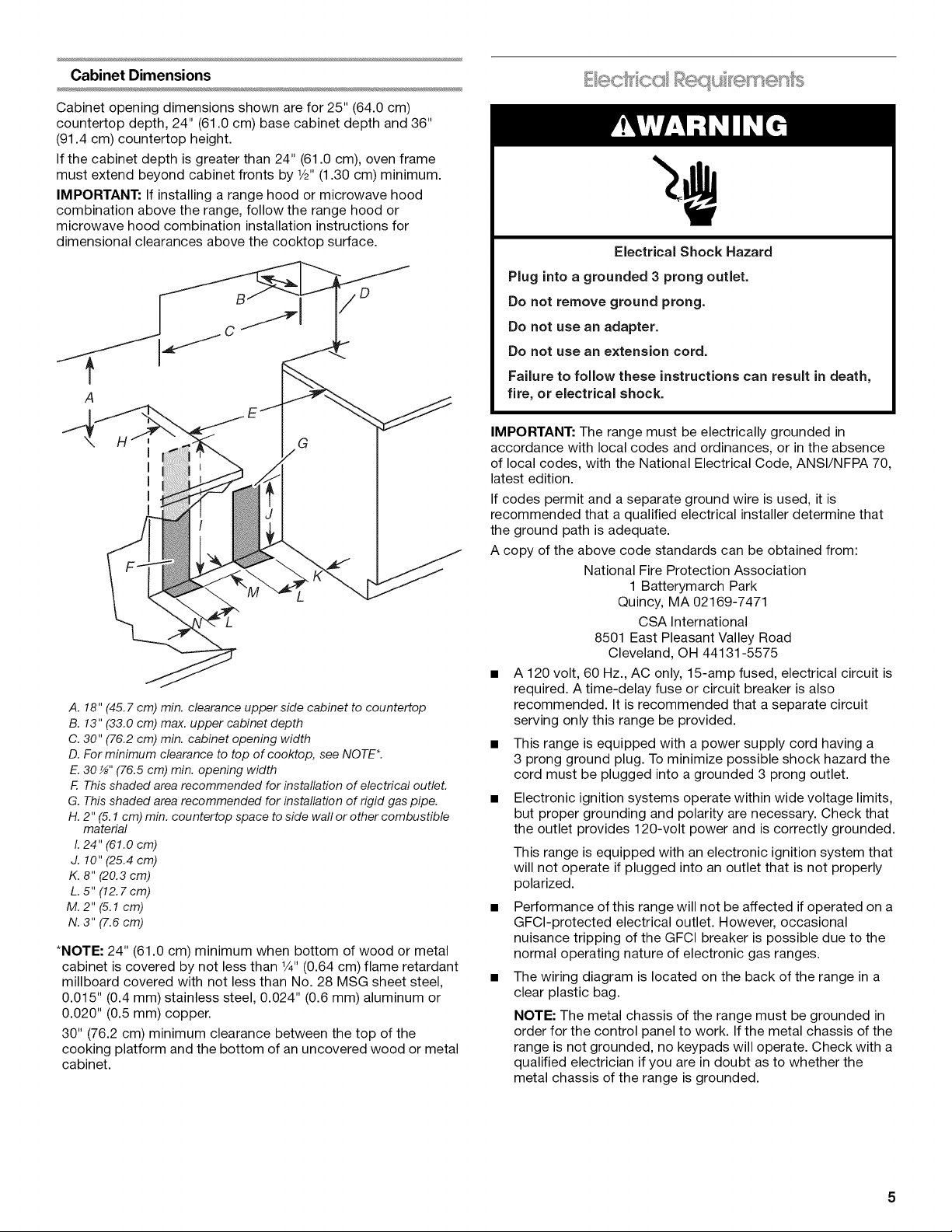
Cabinet Dimensions
Cabinet opening dimensions shown are for 25" (64.0 cm)
countertop depth, 24" (61.0 cm) base cabinet depth and 36"
(91.4 cm) countertop height.
If the cabinet depth is greater than 24" (61.0 cm), oven frame
must extend beyond cabinet fronts by 1/2"(1.30 cm) minimum.
IMPORTANT: If installing a range hood or microwave hood
combination above the range, follow the range hood or
microwave hood combination installation instructions for
dimensional clearances above the cooktop surface.
Electrical Shock Hazard
Plug into a grounded 3 prong outlet.
Do not remove ground prong.
Do not use an adapter.
Do not use an extension cord.
Failure to follow these instructions can result in death,
fire, or electrical shock.
G
A. 18" (45.7 cm) min. clearance upper side cabinet to countertop
B. 13" (33.0 cm) max. upper cabinet depth
C. 30" (76.2 cm) min. cabinet opening width
D. For minimum clearance to top of cooktop, see NOTE*.
E. 30 _" (76.5 cm) min. opening width
R This shaded area recommended for installation of electrical outlet.
G. This shaded area recommended for installation of rigid gas pipe.
H. 2" (5.1 cm) min. countertop space to side wall or other combustible
material
I. 24" (61.0 cm)
J. 10" (25.4 cm)
K. 8" (20.3 cm)
L. 5" (12.7cm)
M. 2"(5.1 cm)
N. 3" (7.6 cm)
*NOTE: 24" (61.0 cm) minimum when bottom of wood or metal
cabinet is covered by not less than Y4"(0.64 cm) flame retardant
millboard covered with not less than No. 28 MSG sheet steel,
0.015" (0.4 mm) stainless steel, 0.024" (0.6 mm) aluminum or
0.020" (0.5 mm) copper.
30" (76.2 cm) minimum clearance between the top of the
cooking platform and the bottom of an uncovered wood or metal
cabinet.
IMPORTANT: The range must be electrically grounded in
accordance with local codes and ordinances, or in the absence
of local codes, with the National Electrical Code, ANSI/NFPA 70,
latest edition.
If codes permit and a separate ground wire is used, it is
recommended that a qualified electrical installer determine that
the ground path is adequate.
A copy of the above code standards can be obtained from:
National Fire Protection Association
1 Batterymarch Park
Quincy, MA 02169-7471
CSA International
8501 East Pleasant Valley Road
Cleveland, OH 44131-5575
• A 120 volt, 60 Hz., AC only, 15-amp fused, electrical circuit is
required. A time-delay fuse or circuit breaker is also
recommended. It is recommended that a separate circuit
serving only this range be provided.
• This range is equipped with a power supply cord having a
3 prong ground plug. To minimize possible shock hazard the
cord must be plugged into a grounded 3 prong outlet.
• Electronic ignition systems operate within wide voltage limits,
but proper grounding and polarity are necessary. Check that
the outlet provides 120-volt power and is correctly grounded.
This range is equipped with an electronic ignition system that
will not operate if plugged into an outlet that is not properly
polarized.
• Performance of this range will not be affected if operated on a
GFCI-protected electrical outlet. However, occasional
nuisance tripping of the GFCI breaker is possible due to the
normal operating nature of electronic gas ranges.
• The wiring diagram is located on the back of the range in a
clear plastic bag.
NOTE: The metal chassis of the range must be grounded in
order for the control panel to work. Ifthe metal chassis of the
range is not grounded, no keypads will operate. Check with a
qualified electrician if you are in doubt as to whether the
metal chassis of the range is grounded.
Explosion Hazard
Use a new CSA International approved gas supply line.
Install a shut=off valve.
Securely tighten all gas connections.
if connected to LP, have a qualified person make sure
gas pressure does not exceed 14" (36 cm) water
column.
Examples of a qualified person include:
licensed heating personnel,
authorized gas company personnel, and
authorized service personnel.
Failure to do so can result in death, explosion, or fire.
Observe all governing codes and ordinances.
IMPORTANT: This installation must conform with all local codes
and ordinances. In the absence of local codes, installation must
conform with American National Standard, National Fuel Gas
Code ANSI Z223.1 - latest edition or CAN/CGA B149 - latest
edition.
IMPORTANT: Leak testing of the range must be conducted
according to the manufacturer's instructions. See "Complete
Connection" in the "Make Gas Connection" section.
Gas Supply Line
• Provide a gas supply line of 3_,,(1.9 cm) rigid pipe to the
range location. A smaller size pipe on longer runs may result
in insufficient gas supply. With LP gas, piping or tubing size
can be 1/2"(1.3 cm) minimum. Usually, LP gas suppliers
determine the size and materials used in the system.
NOTE: Pipe-joint compounds that resist the action of LP gas
must be used. Do not use TEFLON ®ttape.
Flexible metal appliance connector:
• If local codes permit, a new CSA design-certified, 4 to 5 ft
(122 to 152.4 cm) long, 1/2"(1.3 cm) or 34,,(1.9 cm) I.D.,
flexible metal appliance connector may be used for
connecting range to the gas supply line.
• A 1/2"(1.3 cm) male pipe thread is needed for connection
to the female pipe threads of the inlet to the appliance
pressure regulator.
• Do not kink or damage the flexible metal tubing when
moving the range.
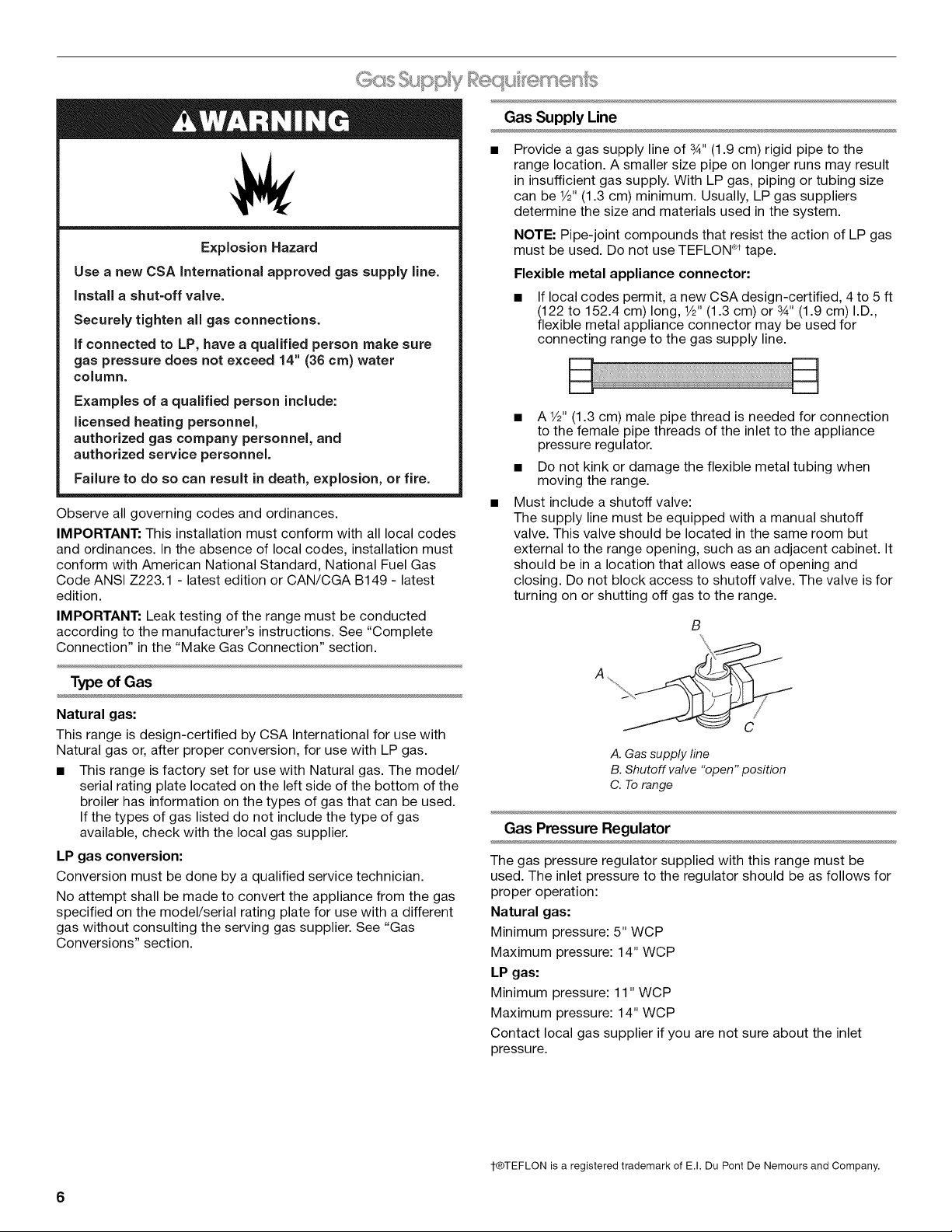
Must include a shutoff valve:
The supply line must be equipped with a manual shutoff
valve. This valve should be located in the same room but
external to the range opening, such as an adjacent cabinet. It
should be in a location that allows ease of opening and
closing. Do not block access to shutoff valve. The valve is for
turning on or shutting off gas to the range.
B
Type of Gas
Natural gas:
This range is design-certified by CSA International for use with
Natural gas or, after proper conversion, for use with LP gas.
• This range is factory set for use with Natural gas. The model/
serial rating plate located on the left side of the bottom of the
broiler has information on the types of gas that can be used.
If the types of gas listed do not include the type of gas
available, check with the local gas supplier.
LP gas conversion:
Conversion must be done by a qualified service technician.
No attempt shall be made to convert the appliance from the gas
specified on the model/serial rating plate for use with a different
gas without consulting the serving gas supplier. See "Gas
Conversions" section.
A. Gas supply line
B. Shutoff valve "open" position
C. To range
Gas Pressure Regulator
The gas pressure regulator supplied with this range must be
used. The inlet pressure to the regulator should be as follows for
proper operation:
Natural gas:
Minimum pressure: 5" WCP
Maximum pressure: 14" WCP
LP gas:
Minimum pressure: 11" WCP
Maximum pressure: 14" WCP
Contact local gas supplier if you are not sure about the inlet
pressure.
1-®TEFLON is a registered trademark of E.I. Du Pont De Nemours and Company.
6
Burner Input Requirements
Gas Supply Pressure Testing
Input ratings shown on the model/serial rating plate are for
elevations up to 2,000 ft (609.6 m).
For elevations above 2,000 ft (609.6 m), ratings are reduced at a
rate of 4% for each 1,000 ft (304.8 m) above sea level (not
applicable for Canada).
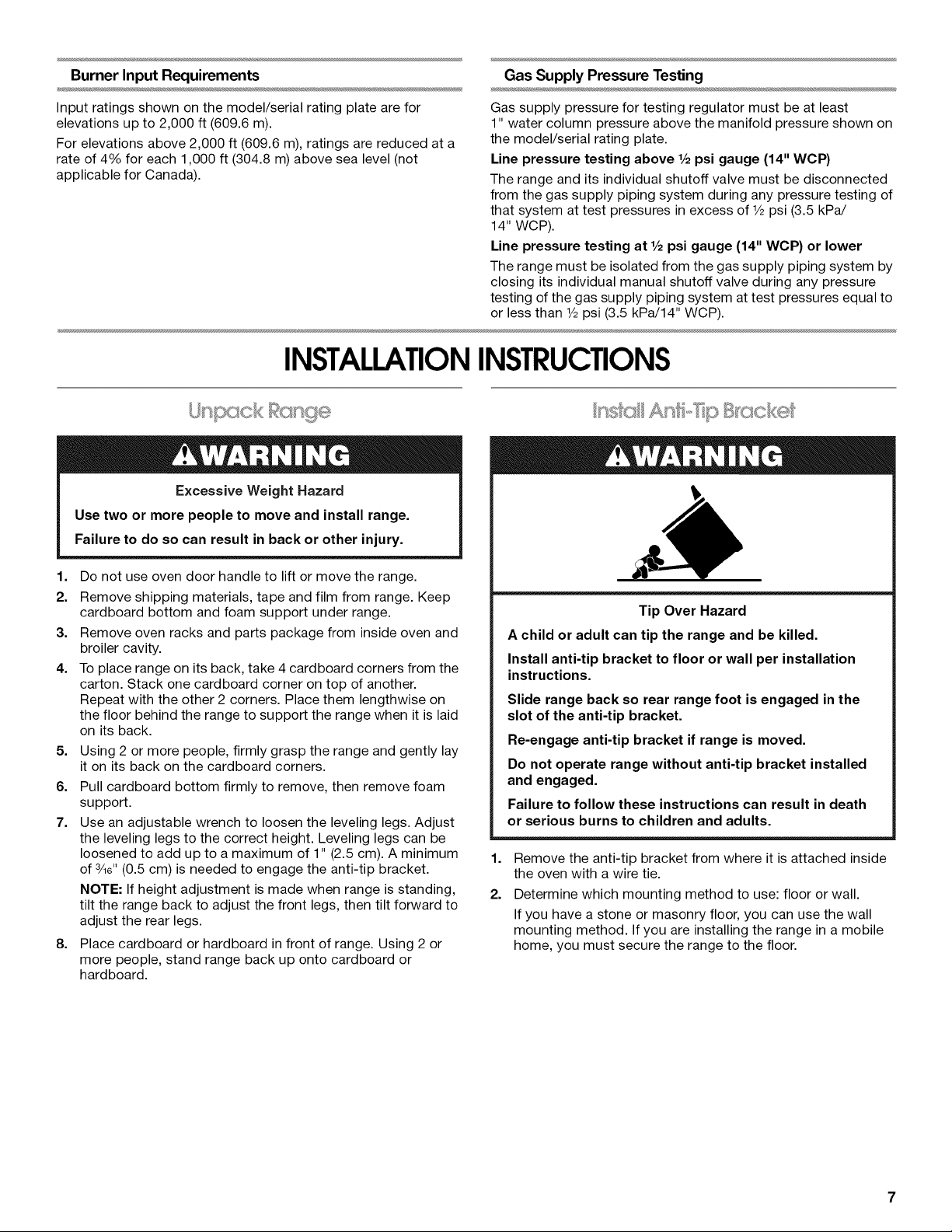
INSTALLATIONINSTRUCTIONS
' .... * Bsn,ge
Excessive Weight Hazard
Use two or more people to move and install range.
Failure to do so can result in back or other injury.
Gas supply pressure for testing regulator must be at least
1" water column pressure above the manifold pressure shown on
the model/serial rating plate.
Line pressure testing above 1/2psi gauge (14" WCP)
The range and its individual shutoff valve must be disconnected
from the gas supply piping system during any pressure testing of
that system at test pressures in excess of 1/2psi (3.5 kPa/
14" WCP).
Line pressure testing at 1/2psi gauge (14" WCP) or lower
The range must be isolated from the gas supply piping system by
closing its individual manual shutoff valve during any pressure
testing of the gas supply piping system at test pressures equal to
or less than 1/2psi (3.5 kPa/14" WCP).
1. Do not use oven door handle to lift or move the range.
2. Remove shipping materials, tape and film from range. Keep
cardboard bottom and foam support under range.
3. Remove oven racks and parts package from inside oven and
broiler cavity.
4. To place range on its back, take 4 cardboard corners from the
carton. Stack one cardboard corner on top of another.
Repeat with the other 2 corners. Place them lengthwise on
the floor behind the range to support the range when it is laid
on its back.
5. Using 2 or more people, firmly grasp the range and gently lay
it on its back on the cardboard corners.
6. Pull cardboard bottom firmly to remove, then remove foam
support.
7. Use an adjustable wrench to loosen the leveling legs. Adjust
the leveling legs to the correct height. Leveling legs can be
loosened to add up to a maximum of 1" (2.5 cm). A minimum
of 3/16"(0.5 cm) is needed to engage the anti-tip bracket.
NOTE: If height adjustment is made when range isstanding,
tilt the range back to adjust the front legs, then tilt forward to
adjust the rear legs.
8. Place cardboard or hardboard in front of range. Using 2 or
more people, stand range back up onto cardboard or
hardboard.
Tip Over Hazard
A child or adult can tip the range and be killed.
Install anti-tip bracket to floor or wall per installation
instructions.
Slide range back so rear range foot is engaged in the
slot of the anti-tip bracket.
Re-engage anti-tip bracket if range is moved.
Do not operate range without anti-tip bracket installed
and engaged.
Failure to follow these instructions can result in death
or serious burns to children and adults.
1,
Remove the anti-tip bracket from where it is attached inside
the oven with a wire tie.
2.
Determine which mounting method to use: floor or wall.
If you have a stone or masonry floor, you can use the wall
mounting method. If you are installing the range in a mobile
home, you must secure the range to the floor.
3,
Determine and mark centerline of the cutout space. The
mounting can be installed on either the left side or right side
of the cutout. Position mounting bracket against the wall in
the cutout so that the V-notch of the bracket is 95/8'' (24.6 cm)
from centerline as shown.
A. 95_''(24.6 cm)
B. Bracket V-notch
4,
Drill two 1/8"(3 mm) holes that correspond to the bracket
holes of the determined mounting method. See the following
illustrations.
Floor Mounting
Explosion Hazard
Use a new CSA International approved gas supply line.
Install a shut-off valve.
Securely tighten all gas connections.
if connected to LP, have a qualified person make sure
gas pressure does not exceed 14" (36 cm) water
column.
Examples of a qualified person include:
licensed heating personnel,
authorized gas company personnel, and
authorized service personnel.
Failure to do so can result in death, explosion, or fire.
Rearposition
Front position Diagonal (2 options)
Wall Mounting
5. Using the Phillips screwdriver, mount anti-tip bracket to the
wall or floor with the two #12 x 15/8'' (4.1 cm) screws provided.
6. Move range close enough to opening to allow for final gas
and electrical connections. Remove shipping base,
cardboard or hardboard from under range.
7. Move range into its final location, making sure rear leveling
leg slides into anti-tip bracket.
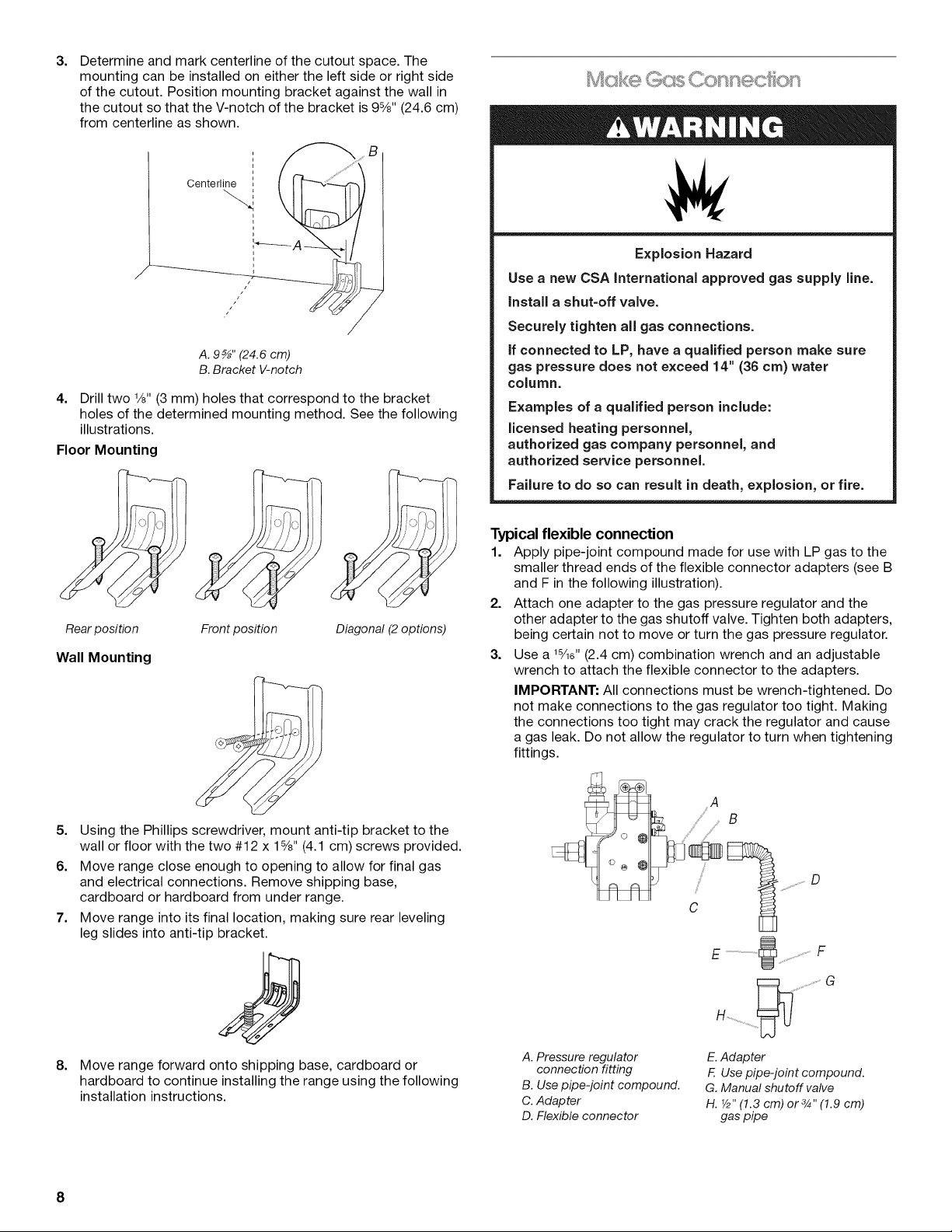
Typical flexible connection
1. Apply pipe-joint compound made for use with LP gas to the
smaller thread ends of the flexible connector adapters (see B
and F in the following illustration).
2. Attach one adapter to the gas pressure regulator and the
other adapter to the gas shutoff valve. Tighten both adapters,
being certain not to move or turn the gas pressure regulator.
3. Use a 1%e" (2.4 cm) combination wrench and an adjustable
wrench to attach the flexible connector to the adapters.
IMPORTANT: All connections must be wrench-tightened. Do
not make connections to the gas regulator too tight. Making
the connections too tight may crack the regulator and cause
a gas leak. Do not allow the regulator to turn when tightening
fittings.
C
G
8,
Move range forward onto shipping base, cardboard or
hardboard to continue installing the range using the following
installation instructions.
8
A. Pressure regulator
connection fitting
B. Use pipe-joint compound.
C. Adapter
D. Flexible connector
E.Adapter
F. Use pipe-joint compound.
G. Manual shutoff valve
H. V2"(1.3 cm) 0r 3/4'' (1.9 cm)
gas pipe
CompleteConnection
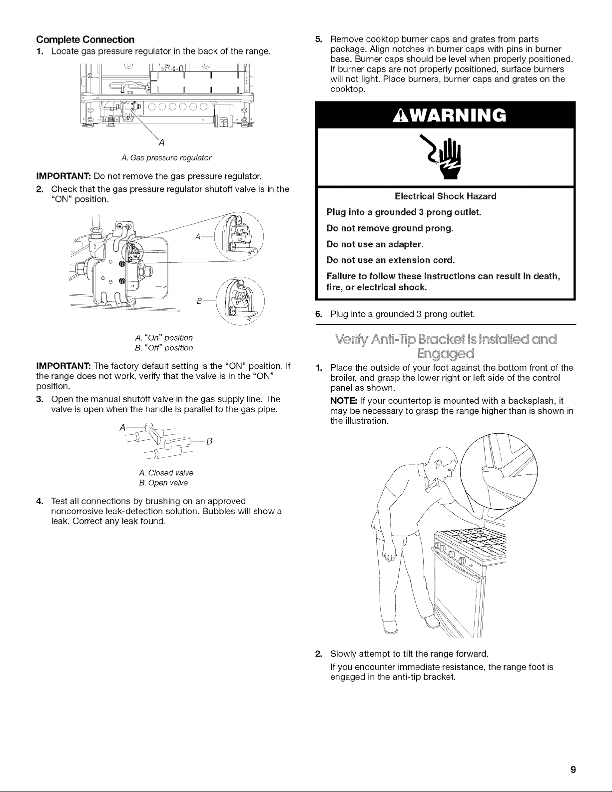
1. Locate gas pressureregulator inthe back of the range.
A.Gas pressure regulator
IMPORTANT: Do not remove the gas pressure regulator.
2. Check that the gas pressure regulator shutoff valve is in the
"ON" position.
5.
Remove cooktop burner caps and grates from parts
package. Align notches in burner caps with pins in burner
base. Burner caps should be level when properly positioned.
If burner caps are not properly positioned, surface burners
will not light. Place burners, burner caps and grates on the
cooktop.
Electrical Shock Hazard
Plug into a grounded 3 prong outlet.
Do not remove ground prong.
Do not use an adapter.
Do not use an extension cord.
Failure to follow these instructions can result in death,
fire, or electrical shock.
6.
Plug into a grounded 3 prong outlet.
A. "On" position
B. "Off" position
IMPORTANT: The factory default setting is the "ON" position. If
the range does not work, verify that the valve is in the "ON"
position.
3. Open the manual shutoff valve in the gas supply line. The
valve is open when the handle is parallel to the gas pipe.
A. Closed valve
B. Open valve
4=
Test all connections by brushing on an approved
noncorrosive leak-detection solution. Bubbles will show a
leak. Correct any leak found.
1=
Place the outside of your foot against the bottom front of the
broiler, and grasp the lower right or left side of the control
panel as shown.
NOTE: If your countertop is mounted with a backsplash, it
may be necessary to grasp the range higher than is shown in
the illustration.
2. Slowly attempt to tilt the range forward.
If you encounter immediate resistance, the range foot is
engaged in the anti-tip bracket.
3. Iftherearoftherangeliftsmorethan1/2"(1.3cm)offthefloor
withoutresistance,stoptiltingtherangeandloweritgently
backtothefloor.Therangefootisnotengagedintheanti-tip
bracket.
IMPORTANT:Ifthereisasnappingorpoppingsoundwhenlifting
therange,therangemaynotbefullyengagedinthebracket.
Checktoseeifthereareobstructionskeepingtherangefrom
slidingtothewallorkeepingtherangefootfromslidingintothe
bracket.Verifythatthebracketisheldsecurelyinplacebythe
mountingscrews.
4. Slidetherangeforward,andverifythattheanti-tipbracketis
securelyattachedtothefloororwall.
5. Sliderangebacksotherearrangefootisinsertedintothe
slotoftheanti-tipbracket.
IMPORTANT:Ifthebackoftherangeismorethan2"(5.1cm)
fromthemountingwall,therearrangefootmaynotengagethe
bracket.Slidetherangeforwardanddetermineifthereisan
obstructionbetweentherangeandthemountingwall.Changes
tothegassupplymustbeperformedbyaqualifiedservice
technician.Ifyouneedassistanceorservice,refertothe
"AssistanceorService"sectionoftheUseandCareGuidefor
contactinformation.
6. Repeatsteps1and2toensurethattherangefootis
engagedintheanti-tipbracket.
Iftherearoftherangeliftsmorethan1/2"(1.3cm)offthefloor
withoutresistance,theanti-tipbracketmaynotbeinstalled
correctly.Donotoperatetherangewithoutanti-tipbracket
installedandengaged.Pleasereferencethe"Assistanceor
Service"sectionoftheUseandCareGuide,orthecoveror
"Warranty"sectionoftheUserInstructions,tocontact
service.
1.
Place a standard flat rack in oven.
2.
Place level on the rack and check levelness of the range, first
side to side; then front to back.
Initial lighting and gas flame adjustments
Cooktop and oven burners use electronic igniters in place of
standing pilots. When the cooktop control knob is turned to the
"IGNITE" position, the system creates a spark to light the burner.
This sparking continues until the control knob is turned to the
desired setting.
When the oven control is turned to the desired setting, a hot
surface igniter heats to a bright orange and ignites the gas. No
sparking occurs. The glow bar remains on while the burner
operates.
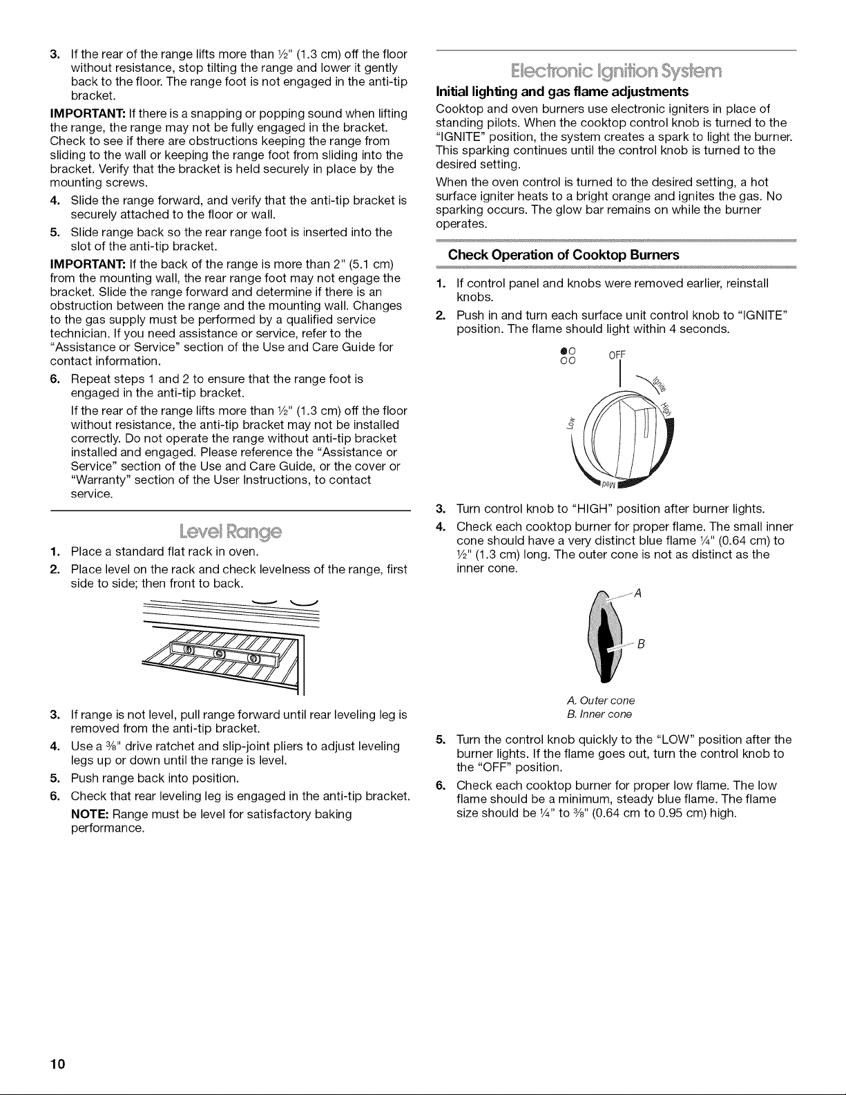
Check Operation of Cooktop Burners
1. If control panel and knobs were removed earlier, reinstall
knobs.
2. Push in and turn each surface unit control knob to "IGNITE"
position. The flame should light within 4 seconds.
oo
eO Oi F
--.%
3.
Turn control knob to "HIGH" position after burner lights.
4.
Check each cooktop burner for proper flame. The small inner
cone should have a very distinct blue flame 1¼,,(0.64 cm) to
1/2"(1.3 cm) long. The outer cone is not as distinct as the
inner cone.
3. If range is not level, pull range forward until rear leveling leg is
removed from the anti-tip bracket.
4. Use a 3/8"drive ratchet and slip-joint pliers to adjust leveling
legs up or down until the range is level.
5. Push range back into position.
6. Check that rear leveling leg is engaged in the anti-tip bracket.
NOTE: Range must be level for satisfactory baking
performance.
10
A. Outer cone
B. Inner cone
5. Turn the control knob quickly to the "LOW" position after the
burner lights. If the flame goes out, turn the control knob to
the "OFF" position.
6. Check each cooktop burner for proper low flame. The low
flame should be a minimum, steady blue flame. The flame
size should be 1¼,to 3/8"(0.64 cm to 0.95 cm) high.
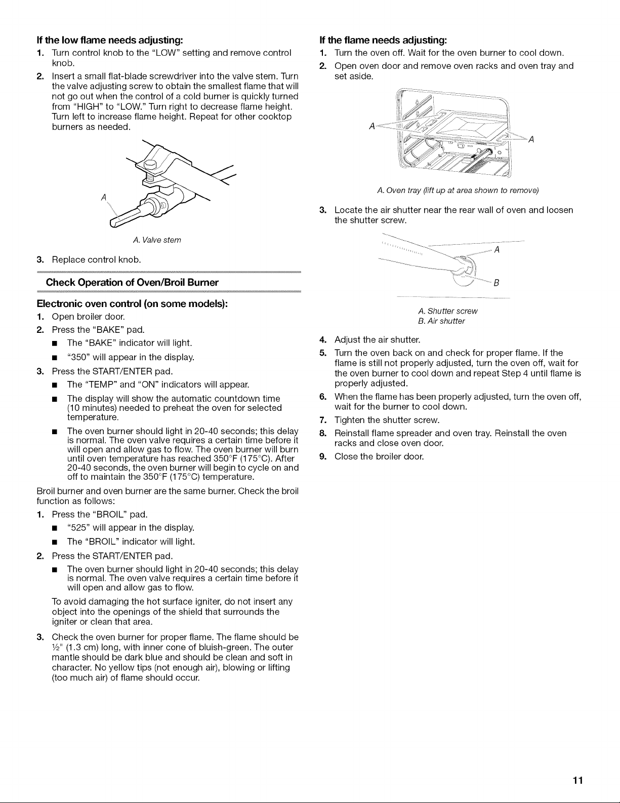
If the low flame needs adjusting:
1. Turn control knob to the "LOW" setting and remove control
knob.
2. Insert a small flat-blade screwdriver into the valve stem. Turn
the valve adjusting screw to obtain the smallest flame that will
not go out when the control of a cold burner is quickly turned
from "HIGH" to "LOW." Turn right to decrease flame height.
Turn left to increase flame height. Repeat for other cooktop
burners as needed.
If the flame needs adjusting:
1. Turn the oven off. Wait for the oven burner to cool down.
2. Open oven door and remove oven racks and oven tray and
set aside.
_2::::::_2::_2z2: .........
A
A. Valve stem
3. Replace control knob.
Check Operation of Oven/Broil Burner
Electronic oven control (on some models):
1. Open broiler door.
2. Press the "BAKE" pad.
• The "BAKE" indicator will light.
• "350" will appear in the display.
3. Press the START/ENTER pad.
• The "TEMP" and "ON" indicators will appear.
• The display will show the automatic countdown time
(10 minutes) needed to preheat the oven for selected
temperature.
• The oven burner should light in 20-40 seconds; this delay
is normal. The oven valve requires a certain time before it
will open and allow gas to flow. The oven burner will burn
until oven temperature has reached 350°F (175°C). After
20-40 seconds, the oven burner will begin to cycle on and
off to maintain the 350°F (175°C) temperature.
Broil burner and oven burner are the same burner. Check the broil
function as follows:
1. Press the "BROIL" pad.
• "525" will appear in the display.
• The "BROIL" indicator will light.
2. Press the START/ENTER pad.
• The oven burner should light in 20-40 seconds; this delay
is normal. The oven valve requires a certain time before it
will open and allow gas to flow.
To avoid damaging the hot surface igniter, do not insert any
object into the openings of the shield that surrounds the
igniter or clean that area.
3. Check the oven burner for proper flame. The flame should be
1/2"(1.3 cm) long, with inner cone of bluish-green. The outer
mantle should be dark blue and should be clean and soft in
character. No yellow tips (not enough air), blowing or lifting
(too much air) of flame should occur.
A.Oven tray (liftup at area shown to remove)
3.
Locate the air shutter near the rear wall of oven and loosen
the shutter screw.
A. Shutter screw
B.Air shutter
4. Adjust the air shutter.
5. Turn the oven back on and check for proper flame. If the
flame is still not properly adjusted, turn the oven off, wait for
the oven burner to cool down and repeat Step 4 until flame is
properly adjusted.
6. When the flame has been properly adjusted, turn the oven off,
wait for the burner to cool down.
7. Tighten the shutter screw.
8. Reinstall flame spreader and oven tray. Reinstall the oven
racks and close oven door.
9. Close the broiler door.
11

1. Check that all parts are now installed. If there is an extra part,
go back through the steps to see which step was skipped.
2. Check that you have all of your tools.
3. Dispose of/recycle all packaging materials.
4. Check that the range is level. See the "Level Range" section.
5. Use a mild solution of liquid household cleaner and warm
water to remove waxy residue caused by shipping material.
Dry thoroughly with a soft cloth. For more information, see
the "Range Care" section of the Use and Care Guide or User
Instructions.
6. Read the Use and Care Guide or User Instructions.
7. Turn on surface burners and oven. See the Use and Care
Guide or User Instructions for specific instruction on range
operation.
If range does not operate, check the following:
• Household fuse is intact and tight, or circuit breaker has not
tripped.
GAS CONVERSIONS
Gas conversions from Natural gas to LP gas or from LP gas to
Natural gas must be done by a qualified installer.
Range is plugged into a grounded 3 prong outlet.
Gas pressure regulator shutoff valve is in the "on" position.
Electrical supply is connected.
See "Troubleshooting" in the Use and Care Guide or User
Instructions.
8.
When the range has been on for 5 minutes, check for heat. If
the range is cold, turn off the range and check that the gas
supply line shutoff valve is open.
• Ifthe gas supply line shutoff valve is closed, open it, then
repeat the 5-minute test as outlined above.
• If the gas supply line shutoff valve is open, press the
CANCEL button on the oven control panel and contact a
qualified technician.
If you need Assistance or Service:
Please reference the "Assistance or Service" section of the Use
and Care Guide or the cover of the User Instructions, or contact
the dealer from whom you purchased your range.
Explosion Hazard
Use a new CSA International approved gas supply line.
instal a shut-off valve.
Securely tighten all gas connections.
if connected to LP, have a qualified person make sure
gas pressure does not exceed 14" (36 cm) water
column.
Examples of a qualified person include:
licensed heating personnel,
authorized gas company personnel, and
authorized service personnel.
Failure to do so can result in death, explosion, or fire.
Tip Over Hazard
A child or adult can tip the range and be killed.
Install anti-tip bracket to floor or wall per installation
instructions.
Slide range back so rear range foot is engaged in the
slot of the anti-tip bracket.
Re-engage anti-tip bracket if range is moved.
Do not operate range without anti-tip bracket installed
and engaged.
Failure to follow these instructions can result in death
or serious burns to children and adults.
1. Turn manual shutoff valve to the "closed" position.
....................B
A__ ........................C
A. Gassupply line
B. Manualshutoff valve "closed" position
C. Torange
12
2. Unplug range or disconnect power.
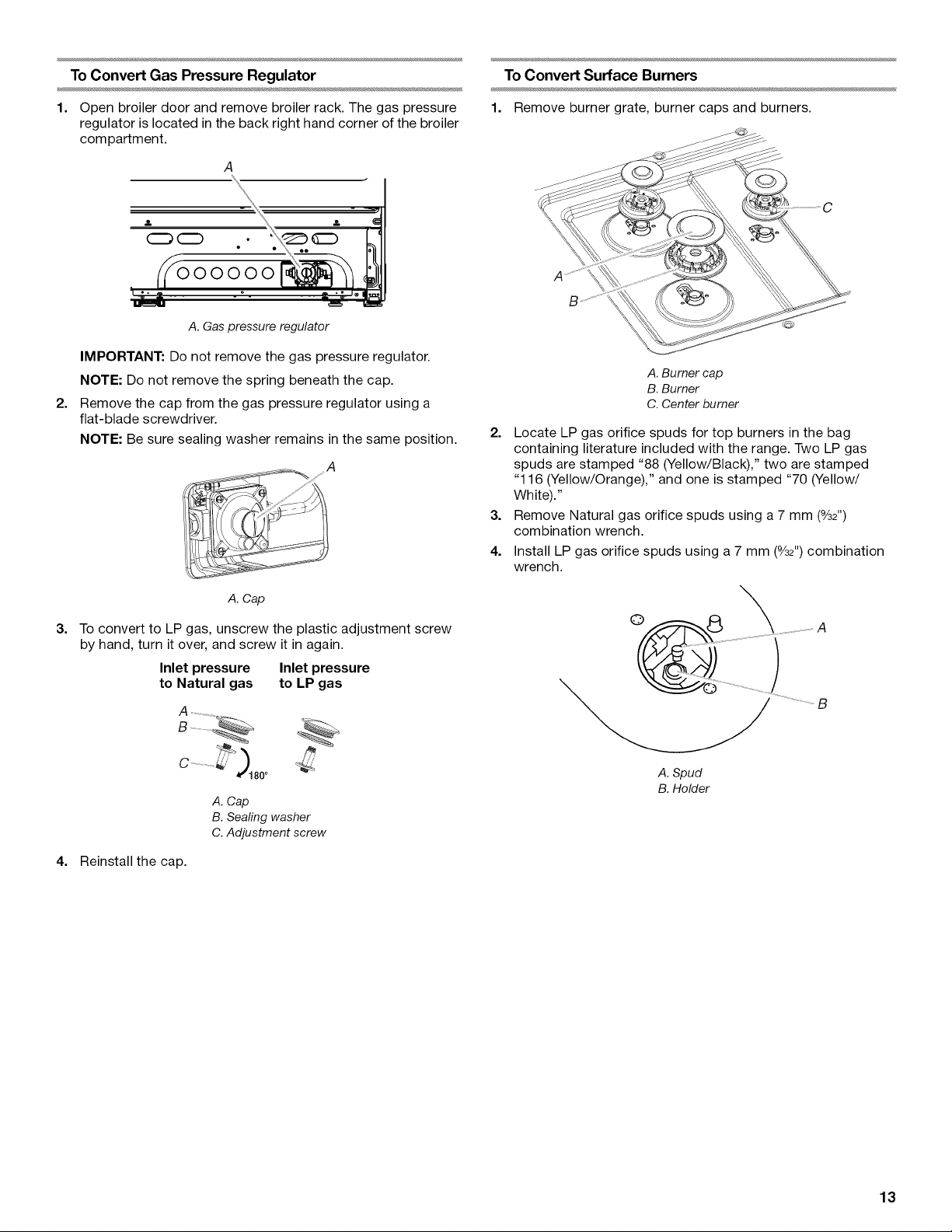
To Convert Gas Pressure Regulator
To Convert Surface Burners
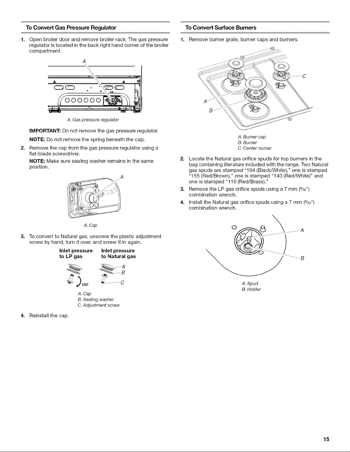
1. Open broiler door and remove broiler rack. The gas pressure
regulator is located inthe back right hand corner of the broiler
compartment.
A
2.
(Z_ (Z)
000000
A. Gas pressure regulator
IMPORTANT: Do not remove the gas pressure regulator.
NOTE: Do not remove the spring beneath the cap.
2=
Remove the cap from the gas pressure regulator using a
flat-blade screwdriver.
NOTE: Be sure sealing washer remains in the same position.
A
1. Remove burner grate,burner caps and burners.
A. Burner cap
B. Burner
C. Center burner
2. Locate LP gas orifice spuds for top burners in the bag
containing literature included with the range. Two LP gas
spuds are stamped "88 (Yellow/Black)," two are stamped
"116 (Yellow/Orange)," and one is stamped "70 (Yellow/
White)."
3. Remove Natural gas orifice spuds using a 7 mm (%2")
combination wrench.
4. Install LP gas orifice spuds using a 7 mm (%2") combination
wrench.
A. Cap
3=
To convert to LP gas, unscrew the plastic adjustment screw
by hand, turn it over, and screw it in again.
Inlet pressure Inlet pressure
to Natural gas to LP gas
A. Cap
B. Sealing washer
C. Adjustment screw
4. Reinstall the cap.
©
A. Spud
B.Holder
13
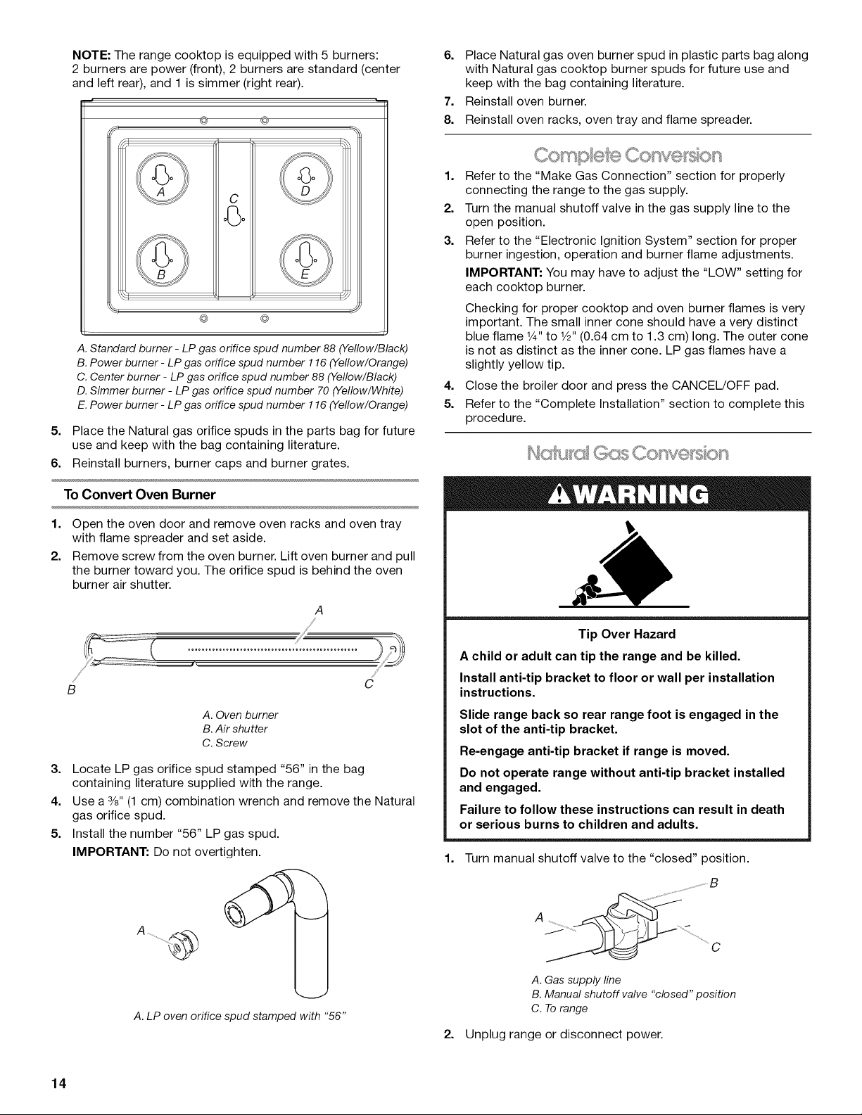
NOTE: The range cooktop is equipped with 5 burners:
2 burners are power (front), 2 burners are standard (center
and left rear), and 1 is simmer (right rear).
@ ©
P
C
-i
@ @
....... q
A. Standardburner - LP gas orifice spud number 88 (Yellow/Black)
B.Power burner - LPgas orifice spudnumber 116 (Yellow/Orange)
C. Center burner - LP gas orifice spud number 88 (Yellow/Black)
D. Simmer burner - LP gas orifice spud number 70 (Yellow/White)
E.Power burner - LP gas orifice spudnumber 116 (Yellow/Orange)
5. Place the Natural gas orifice spuds in the parts bag for future
use and keep with the bag containing literature.
6. Reinstall burners, burner caps and burner grates.
6. Place Natural gas oven burner spud in plastic parts bag along
with Natural gas cooktop burner spuds for future use and
keep with the bag containing literature.
7. Reinstall oven burner.
8. Reinstall oven racks, oven tray and flame spreader.
1. Refer to the "Make Gas Connection" section for properly
connecting the range to the gas supply.
2. Turn the manual shutoff valve in the gas supply line to the
open position.
3. Refer to the "Electronic Ignition System" section for proper
burner ingestion, operation and burner flame adjustments.
IMPORTANT: You may have to adjust the "LOW" setting for
each cooktop burner.
Checking for proper cooktop and oven burner flames is very
important. The small inner cone should have a very distinct
blue flame 1¼,,to 1/2"(0.64 cm to 1.3 cm) long. The outer cone
is not as distinct as the inner cone. LP gas flames have a
slightly yellow tip.
4. Close the broiler door and press the CANCEL/OFF pad.
5. Refer to the "Complete Installation" section to complete this
procedure.
To Convert Oven Burner
1. Open the oven door and remove oven racks and oven tray
with flame spreader and set aside.
2. Remove screw from the oven burner. Lift oven burner and pull
the burner toward you. The orifice spud is behind the oven
burner air shutter.
A
,/,,¢"
B
A. Oven burner
B.Air shutter
C. Screw
3=
Locate LP gas orifice spud stamped "56" in the bag
C
containing literature supplied with the range.
4.
Use a 3/8"(1 cm) combination wrench and remove the Natural
gas orifice spud.
5.
Install the number "56" LP gas spud.
IMPORTANT: Do not overtighten.
Tip Over Hazard
A child or adult can tip the range and be killed.
Install anti-tip bracket to floor or wall per installation
instructions.
Slide range back so rear range foot is engaged in the
slot of the anti-tip bracket.
Re-engage anti-tip bracket if range is moved.
Do not operate range without anti-tip bracket installed
and engaged.
Failure to follow these instructions can result in death
or serious burns to children and adults.
1. Turn manual shutoff valve to the "closed" position.
.....................B
14
A. LP oven orifice spud stamped with "56"
A_ ................. J .........._.......................C
A.Gas supply line
B.Manual shutoff valve "closed" position
C. Torange
2. Unplug range or disconnect power.
To Convert Gas Pressure Regulator
To Convert Surface Burners
1. Open broiler door and remove broiler rack. The gas pressure
regulator is located inthe back right hand corner of the broiler
compartment.
A
2.
(Z_ (Z)
000000
A. Gas pressure regulator
IMPORTANT: Do not remove the gas pressure regulator.
NOTE: Do not remove the spring beneath the cap.
2=
Remove the cap from the gas pressure regulator using a
flat-blade screwdriver.
NOTE: Make sure sealing washer remains in the same
position.
A
1. Remove burner grate,burner caps and burners.
A. Burner cap
B. Burner
C. Center burner
2. Locate the Natural gas orifice spuds for top burners in the
bag containing literature included with the range. Two Natural
gas spuds are stamped "194 (Black/White)," one is stamped
"155 (Red/Brown)," one is stamped "140 (Red/White)" and
one is stamped "110 (Red/Brass)."
3. Remove the LP gas orifice spuds using a 7 mm (%2")
combination wrench.
4. Install the Natural gas orifice spuds using a 7 mm (%2")
combination wrench.
A. Cap
3=
To convert to Natural gas, unscrew the plastic adjustment
screw by hand, turn it over, and screw it in again.
Inlet pressure Inlet pressure
to LP gas to Natural gas
2........................................
A.Cap
B. Sealing washer
C. Adjustment screw
4. Reinstall the cap.
©
A. Spud
B.Holder
15
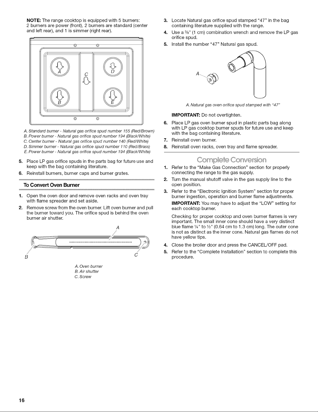
NOTE: The range cooktop is equipped with 5 burners:
2 burners are power (front), 2 burners are standard (center
and left rear), and 1 is simmer (right rear).
@ ©
C
3. Locate Natural gas orifice spud stamped "47" in the bag
containing literature supplied with the range.
4. Use a %" (1 cm) combination wrench and remove the LP gas
orifice spud.
5. Install the number "47" Natural gas spud.
I I¸
@ @
A. Standard burner - Natural gas orifice spud number 155 (Red/Brown)
B. Power burner - Natural gas orifice spud number 194 (Black/White)
C. Center burner - Natural gas orifice spud number 140 (Red/White)
D. Simmer burner - Natural gas orifice spud number 110 (Red/Brass)
E. Power burner - Natural gas orifice spud number 194 (Black/White)
5. Place LP gas orifice spuds in the parts bag for future use and
keep with the bag containing literature.
6. Reinstall burners, burner caps and burner grates.
To Convert Oven Burner
1. Open the oven door and remove oven racks and oven tray
with flame spreader and set aside.
2. Remove screw from the oven burner. Lift oven burner and pull
the burner toward you. The orifice spud is behind the oven
burner air shutter.
A
/
B
A. Oven burner
B.Air shutter
C. Screw
C
A. Natural gas oven orifice spud stamped with "47"
IMPORTANT: Do not overtighten.
6. Place LP gas oven burner spud in plastic parts bag along
with LP gas cooktop burner spuds for future use and keep
with the bag containing literature.
7. Reinstall oven burner.
8. Reinstall oven racks, oven tray and flame spreader.
1. Refer to the "Make Gas Connection" section for properly
connecting the range to the gas supply.
2. Turn the manual shutoff valve in the gas supply line to the
open position.
3. Refer to the "Electronic Ignition System" section for proper
burner ingestion, operation and burner flame adjustments.
IMPORTANT: You may have to adjust the "LOW" setting for
each cooktop burner.
Checking for proper cooktop and oven burner flames is very
important. The small inner cone should have a very distinct
blue flame 1¼,,to 1/2"(0.64 cm to 1.3 cm) long. The outer cone
is not as distinct as the inner cone. Natural gas flames do not
have yellow tips.
4. Close the broiler door and press the CANCEL/OFF pad.
5. Refer to the "Complete Installation" section to complete this
procedure.
16
SECURITEDELACUISINIERE
Votre securite et celle des autres est tres importante.
Nous donnons de nombreux messages de s6curit6 importants dans ce manuel et sur votre appareil m6nager. Assurez-vous de
toujours lire tousles messages de s6curit6 et de vous y conformer.
Ce symbole d'alerte de s6curit6 vous signale les dangers potentiels de d6c_s et de blessures graves & vous
et & d'autres.
Voici le symbole d'alerte de s6curit&
Tous les messages de s6curit6 suivront le symbole d'alerte de s6curit6 et le mot "DANGER" ou
"AVERTISSEMENT". Ces mots signifient •
Risque possible de d_cbs ou de blessure grave si vous ne
suivez pas imm_diatement les instructions.
Risque possible de d_cbs ou de blessure grave si vous
ne suivez pas les instructions.
Tous les messages de s6curit6 vous diront quel est le danger potentiel et vous disent comment r6duire le risque de blessure et
ce qui peut se produire en cas de non-respect des instructions.
AVERTISSEMENT • Si les renseignements dans ce manuel ne sont pas exactement
observes, un incendie ou une explosion peut survenir, causant des dommages au
produit, des blessures ou un d6cbs.
- Ne pas entreposer ni utiliser de I'essence ou d'autres vapeurs ou liquides inflammables
proximite de cet appareil ou de tout autre appareil electrom6nager.
-QUE FAIRE DANS LE CAS D'UNE ODEUR DE GAZ :
• Ne pas tenter d'allumer un appareil.
• Ne pas toucher & un commutateur electrique.
• Ne pas utiliser le tel6phone se trouvant sur les lieux.
• Appeler immediatement le fournisseur de gaz & partir du tel6phone d'un voisin. Suivre
ses instructions.
• .&.defaut de joindre votre fournisseur de gaz, appeler les pompiers.
- L'installation et I'entretien doivent 6tre effectues par un installateur qualifie, une agence
de service ou le fournisseur de gaz.
AVERTISSEMENT : L'odorat ne permet pas toujours la detection d'une fuite de gaz.
Les distributeurs de gaz recommandent I'emploi d'un detecteur de gaz (homologation UL ou CSA).
Pour d'autre information, contacter le fournisseur de gaz local.
En cas de detection d'une fuite de gaz, executer les instructions "Que faire dans le cas d'une odeur de gaz".
iMPORTANT : Ne pas installer un syst_me de ventilation avec 6vacuation de I'air vers le bas, qui 6vacuerait I'air vers cet
appareil de cuisson & gaz. Ce type de syst_me de ventilation peut causer des probl_mes d'allumage et de combustion avec cet
appareil de cuisson & gaz et entrainer des blessures corporelles ou le fonctionnement non d6sir6 de cet appareil.
17
Dans 1'12tatdu Massachusetts, les instructions d'installation suivantes sont applicables :
• Les travaux d'installation et r_paration doivent 6tre executes par un plombier ou tuyauteur qualifi_ ou licenci_, ou par le
personnel qualifi_ d'une entreprise licenci_e par 1'12tatdu Massachusetts.
• Si une vanne & boisseau sph_rique est utilis_e, elle doit comporter une manette "T".
• Si un conduit de raccordement flexible est utilis_, sa Iongueur ne doit pas d_passer 3 pi.
Risque de basculement
Un enfant ou une personne adulte peut faire basculer la cuisiniere, ce qui peut causer un
dbcbs.
Fixer la bride antibasculement au plancher ou au mur, conform_ment aux instructions
d'installation.
Faire glisser de nouveau la cuisiniere de fa£on a ce que le pied arriere de la cuisiniere se
trouve dans la fente de la bride antibasculement.
R_engager la bride antibasculement si la cuisiniere a _t_ dbplac_e.
Ne pas faire fonctionner la cuisiniere si la bride antibasculement n'est pas install_e et engag_e.
Le non-respect de ces instructions peut causer un dbcbs ou des br_lures graves aux enfants et
aux adultes.
Pour v_rifier que la bride antibasculement est bien install_e et engag_e :
Bride
antibasculement
Pied de
la cuisiniere
• Faire glisser la cuisiniere vers I'avant.
• V_rifier que la bride antibasculement est bien fix_e au plancher ou au mur.
• Faire de nouveau glisser la cuisiniere vers I'arriere de sorte que le pied de la cuisiniere
se trouve sous la bride antibasculement.
• Voir les instructions d'installation pour plus de d_tails.
EXIGENCESD'INSTALLATION
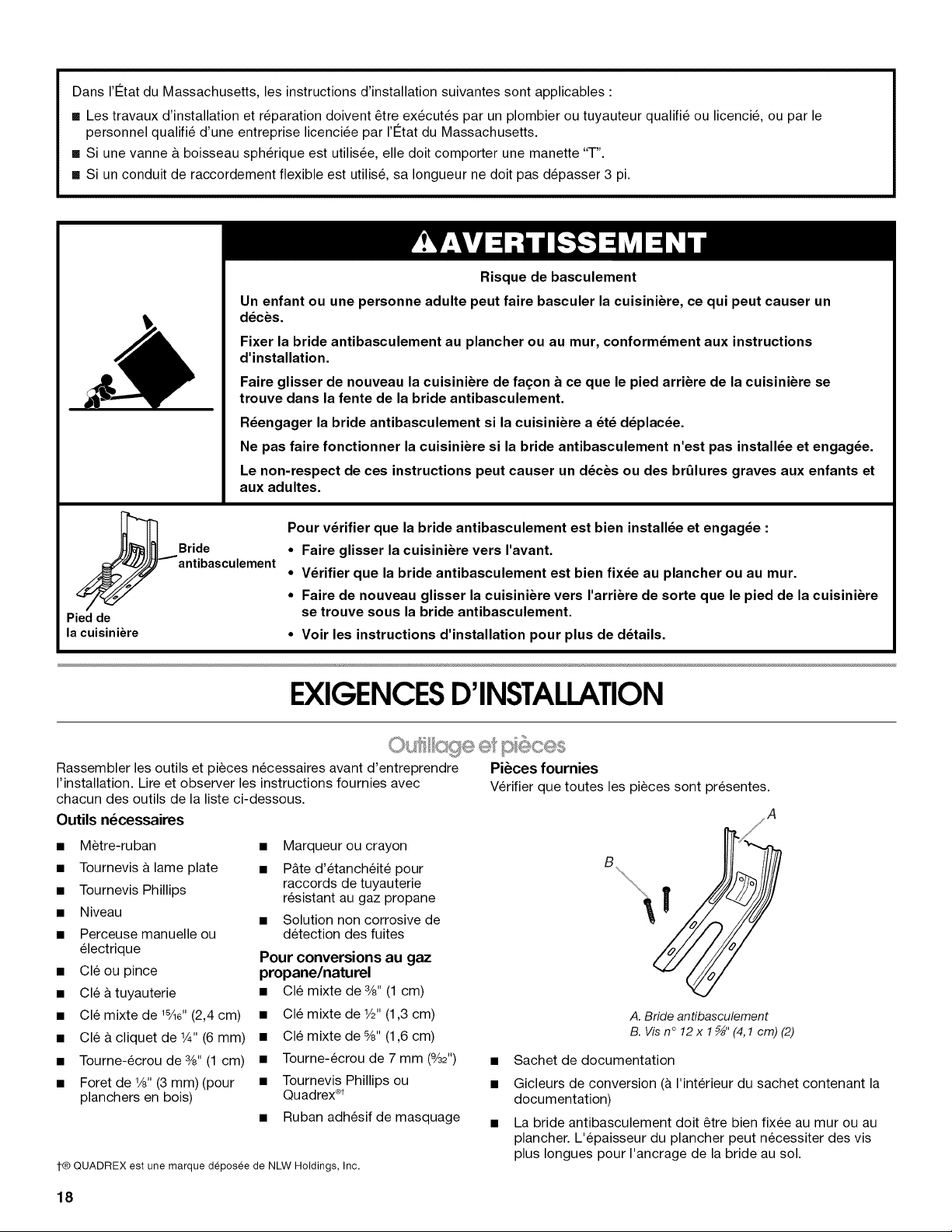
Rassembler les outils et pieces necessaires avant d'entreprendre Pi_ces fournies
I'installation. Lire et observer les instructions fournies avec Verifier que toutes les pieces sont presentes.
chacun des outils de la liste ci-dessous.
Outils n_cessaires A
• M_tre-ruban
• Tournevis a lame plate
• Tournevis Phillips
• Niveau
• Perceuse manuelle ou
electrique
• Cleou pince
• Cle a tuyauterie
• Cle mixte de 18/ls"(2,4 cm)
• Cle & cliquet de 1¼,,(6 mm)
• Tourne-ecrou de 3/8"(1 cm)
• Foret de 1/8"(3 mm) (pour
planchers en bois)
1-@QUADREX est une marque deposee de NLW Holdings, Inc.
• Marqueur ou crayon
• P&te d'etanch6it6 pour
raccords de tuyauterie
resistant au gaz propane
• Solution non corrosive de
detection des fuites
Pour conversions au gaz
propane/naturel
• Cle mixte de 3/8"(1 cm)
• Cle mixte de V="(1,3 cm)
• Cle mixte de %" (1,6 cm)
• Tourne-ecrou de 7 mm (%2")
• Tournevis Phillips ou
Quadrex _
• Ruban adhesif de masquage
A. Bride antibasculement
B. Vis n°12 x1_" (4,1cm) (2)
Sachet de documentation
Gicleurs de conversion (& I'interieur du sachet contenant la
documentation)
La bride antibasculement doit _tre bien fixee au mur ou au
plancher. L'epaisseur du plancher peut necessiter des vis
plus Iongues pour I'ancrage de la bride au sol.
18
Pi_ces n_cessaires
Verifier les codes Iocaux et consulter le fournisseur de gaz.
Verifier I'alimentation en gaz et I'alimentation electrique
existantes. Voir les sections "Specifications electriques" et
"Specifications de I'alimentation en gaz".
c.......................d @v okc cement
IMPORTANT : Observer les dispositions de tousles codes et
r_glements en vigueur. Ne pas obstruer le flux de combustion et
de ventilation.
• C'est a I'installateur qu'incombe la responsabilite de
respecter les distances de separation exigees, specifi6es sur
la plaque signaletique de I'appareil. La plaque signaletique se
trouve sur le chassis du four, derriere le c6te gauche de la
partie inferieure du gril.
A ................................................
A. Emplacement de la plaque signal#tique
La cuisiniere doit _tre installee a un endroit pratique dans la
cuisine.
Dans le cas d'une cuisiniere encastree, I'enceinte doit
recouvrir completement les c6tes et I'arriere de la cuisiniere.
Afin de supprimer le risque de brQlures ou d'incendie lie au
fait de se pencher au-dessus des unites de surface
chauffees, le rangement en armoire au-dessus des unites de
surface doit _tre evit& Si un rangement en armoire est
envisage, le risque peut _tre reduit par I'installation d'une
hotte de cuisine operant horizontalement sur un minimum de
5" (12,7 cm) au-dela du bas des armoires.
Toutes les ouvertures dans le mur ou le plancher de
I'emplacement d'installation de la cuisiniere doivent _tre
scellees.
• Ne pas sceller la cuisiniere aux placards lateraux.
• Respecter les dimensions indiquees pour les ouvertures
decouper dans les placards. Ces dimensions constituent les
valeurs minimales des degagements de separation.
• La bride antibasculement doit _tre installee. Pour I'installation
de la bride antibasculement expedi6e avec la cuisiniere, voir
la section "Installation de la bride antibasculement".
• Une source d'electricit6 avec liaison &la terre est necessaire.
Voir la section "Specifications electriques".
• Une source de gaz adequate doit _tre disponible. Voir la
section "Specifications de I'alimentation en gaz".
• Contacter un installateur de rev_tement de sol qualifie, qui
pourra determiner si le rev_tement de sol peut resister a une
temperature d'au moins 200°F (93°C).
• Dans le cas de I'installation de la cuisiniere sur un tapis,
placer sous la cuisiniere une plaque d'appui isolee, ou une
plaque de contreplaqu_ de W' (0,64 cm).
IMPORTANT : Afin d'eviter d'endommager les placards,
consulter le constructeur de la maison ou le fabricant des
placards pour determiner si les materiaux utilises peuvent subir
un changement de couleur, une destratification ou d'autres
dommages. Ce four a ete con(_u conformement aux exigences
des normes UL et CSA International et respecte les temperatures
maximales permises de 194 ° (90°C) pour les placards en bois.
R_sidence mobile - Specifications additionnelles
respecter Iors de I'installation
L'installation de cette cuisiniere doit _tre conforme aux
dispositions de la norme Manufactured Home Construction and
Safety Standard, Title 24 CFR, Part 3280 (anciennement Federal
Standard for Mobile Home Construction and Safety, Title 24,
HUD Part 280). Lorsque cette norme n'est pas applicable,
I'installation doit satisfaire aux criteres de la norme Standard for
Manufactured Home Installations, ANSI A225.1/NFPA 501A ou
aux dispositions des codes Iocaux.
Au Canada, I'installation de cette cuisiniere doit satisfaire aux
stipulations de la version la plus recente de la norme CAN/CSA-
A240 ou des codes Iocaux en vigueur.
Autres crit_res a respecter pour une installation en r_sidence
mobile :
• Dans le cas de I'installation de cette cuisiniere dans une
residence mobile, la cuisiniere doit _tre fixee au plancher
durant tout deplacement du vehicule. Toute methode de
fixation de la cuisiniere est adequate dans la mesure oQelle
satisfait aux criteres des normes mentionnees ci-dessus.
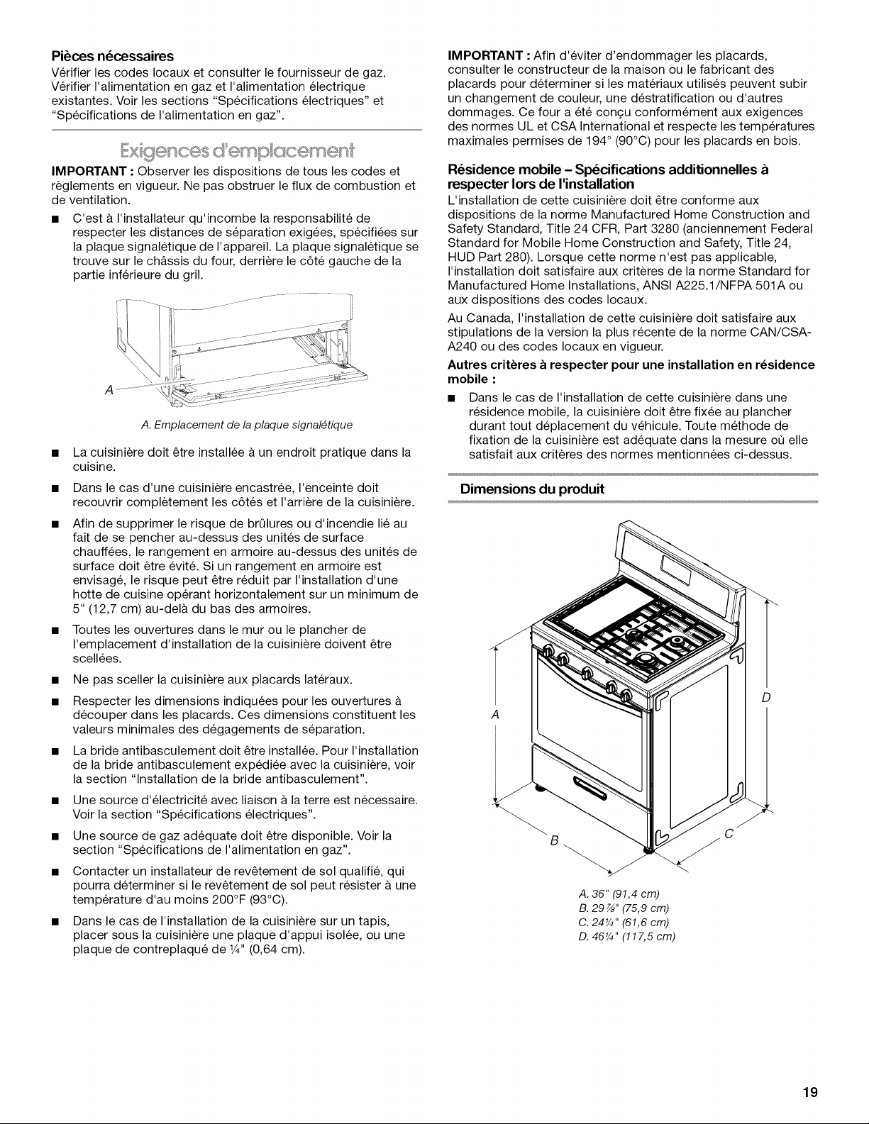
Dimensions du produit
D
B
A. 36" (91,4 cm)
B. 29 z_,,(75,9 cm)
C. 24¼" (61,6 cm)
D. 46¼" (117,5 cm)
C
19
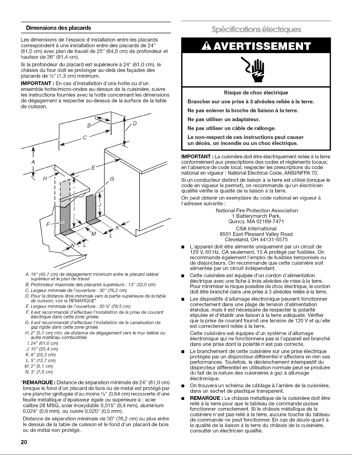
Dimensions des placards
Les dimensions de I'espace d'installation entre les placards
correspondent & une installation entre des placards de 24"
(61,0 cm) avec plan de travail de 25" (64,0 cm) de profondeur et
hauteur de 36" (91,4 cm).
Si la profondeur du placard est superieure & 24" (61,0 cm), le
chassis du four dolt se prolonger au-del& des fagades des
placards de 1/2"(1,3 cm) minimum.
IMPORTANT • En cas d'installation d'une hotte ou d'un
ensemble hotte/micro-ondes au-dessus de la cuisiniere, suivre
les instructions fournies avec la hotte concernant les dimensions
de degagement & respecter au-dessus de la surface de la table
de cuisson.
b
Risque de choc _lectrique
Brancher sur une prise _ 3 aJv_oles reli_e a Jaterre.
Ne pas enJever la broche de liaison & la terre.
Ne pas utiliser un adaptateur.
Ne pas utiJiser un c&ble de rallonge.
Le non=respect de ces instructions peut causer
un d_c_s, un incendie ou un choc 61ectrique.
A
G
A. 18" (45,7 cm) de d#gagement minimum entre le placard lateral
sup#rieur et le plan de travail
B. Profondeur maximale des placards sup#rieurs : 13" (33,0 cm)
C. Largeur minimale de I'ouverture : 30" (76,2 cm)
D. Pour la distance fibre minimale vers la partie sup#rieure de la table
de cuisson, voir la REMARQUE*
E. Largeur minimale de I'ouverture : 30 _" (76,5 cm)
F. II est recommand# d'effectuer I'installation de la prise de courant
#lectrique dans cette zone gris#e.
G. II est recommand# d 'effectuer I'installation de la canalisation de
gaz rigide dans cette zone gris#e.
H. 2" (5,1 cm) min. de distance de d#gagement vers lemur lateral ou
autre mat#riau combustible
I. 24" (61,0 cm)
J. 10" (25,4 cm)
K. 8" (20,3 cm)
L. 5" (12,7cm)
M 2"(5,1cm)
N. 3" (7,6 cm)
*REMARQUE • Distance de separation minimale de 24" (61,0 cm)
Iorsque le fond d'un placard de bois ou de metal est protege par
une planche ignifugee d'au moins 1¼,,(0,64 cm) recouverte d'une
feuille metallique d'epaisseur egale ou superieure &: acier
calibre 28 MSG, acier inoxydable 0,015" (0,4 mm), aluminium
0,024" (0,6 mm), ou cuivre 0,020" (0,5 mm).
Distance de separation minimale de 30" (76,2 cm) ou plus entre
le dessus de la table de cuisson et le fond d'un placard de bois
ou de metal non protege.
IMPORTANT : La cuisiniere dolt _tre electriquement reliee &la terre
conformement aux prescriptions des codes et reglements Iocaux;
en I'absence de code local, respecter les prescriptions du code
national en vigueur : National Electrical Code, ANSI/NFPA 70.
Si un conducteur distinct de liaison & la terre est utilise (Iorsque le
code en vigueur le permet), on recommande qu'un electricien
qualifie verifie la qualite de la liaison & la terre.
On peut obtenir un exemplaire du code national en vigueur
I'adresse suivante :
National Fire Protection Association
1 Batterymarch Park,
Quincy, MA 02169-7471
CSA International
8501 East Pleasant Valley Road
Cleveland, OH 44131-5575
L'appareil dolt _tre alimente uniquement par un circuit de
120 V, 60 Hz, CA seulement, 15 A protege par fusibles. On
recommande egalement I'emploi de fusibles temporises ou
de disjoncteurs. On recommande que cette cuisiniere soit
alimentee par un circuit independant.
Cette cuisiniere est equipee d'un cordon d'alimentation
electrique avec une fiche & trois alveoles de mise & la terre.
Pour minimiser le risque possible de choc electrique, lecordon
dolt _tre branche dans une prise &3 alveoles reliee & la terre.
Les dispositifs d'allumage electronique peuvent fonctionner
correctement dans une plage de tension d'alimentation
etendue, mais il est necessaire de respecter la polarite
stipulee et d'etablir une liaison & la terre adequate. Verifier
que la prise de courant fournit une tension de 120 Vet qu'elle
est correctement reliee a la terre.
Cette cuisiniere est equipee d'un systeme d'allumage
electronique qui ne fonctionnera pas si I'appareil est branche
dans une prise dont la polarite n'est pas correcte.
Le branchement de cette cuisiniere sur une prise electrique
protegee par un disjoncteur differentiel n'affectera en rien ses
performances. Toutefois, le declenchement intempestif du
disjoncteur differentiel en utilisation normale peut se produire
du fait de la nature des cuisinieres a gaz &allumage
electronique.
On trouvera un schema de c&blage & I'arriere de la cuisiniere,
dans un sachet de plastique transparent.
REMARQUE : Le chassis metallique de la cuisiniere dolt _tre
relie & la terre pour que le tableau de commande puisse
fonctionner correctement. Si le chassis metallique de la
cuisiniere n'est pas relie a la terre, aucune touche du tableau
de commande ne peut fonctionner. En cas de doute quant
la qualite de la liaison & la terre du chassis de la cuisiniere,
consulter un electricien qualifi&
20
 Loading...