

Whirlpool WEE750H0H, WEEA25H0H Specifications
Electric Slide-In Range Installation Instructions
A
PRODUCT MODEL NUMBERS
WEE750H0H WEEA25H0H
Installation Requirements
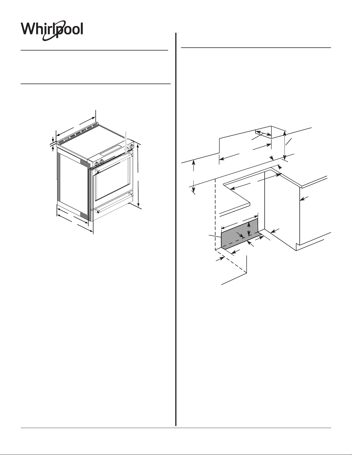
PRODUCT DIMENSIONS
These instructions cover several models. Your model may appear
different from the models depicted. Dimensions given are maximum
dimensions across all models.
Model WEE750H0H
B
C
D
CABINET DIMENSIONS
Cabinet opening dimensions shown are for 25" (64.0 cm) countertop
depth, 24" (61.0 cm) base cabinet depth and 36" (91.4 cm) countertop
height.
IMPORTANT: If installing a range hood or microwave hood combination
above the range, follow the range hood or microwave hood combination
installation instructions for dimensional clearances above the cooktop
surface.
Range may be installed next to combustible walls with zero clearance.
NOTE: When installed in a slide-in cutout, the front of oven door may
protrude beyond the base cabinet.
Slide-In Cutout
D
B
C
L
A
E
K
E
F
G
H
I
F
A. 13/16" (3.0 cm) height from
cooktop to top of vent
7
B. 29
/8" (75.9 cm)
C. Model/serial/rating plate
(located behind the oven door
on the top right-hand side of
the oven frame)
D. 36" (91.4 cm) height to top of
cooktop edge with leveling
legs screwed in all the way*
IMPORTANT: Range must be level after installation. Follow the
instructions in the “Level Range” section. Using the cooktop as
a reference for leveling the range is not recommended.
* Range can be raised approximately 1” (2.5 cm) by adjusting the
leveling legs.
E. 27" (68.8 cm)
5
F. 28
/8" (72.7 cm) max. depth
from handle to back of range
J
I
A. 18" (45.7 cm) upper side cabinet to countertop
B. 13" (33 cm) max. upper cabinet depth
C. 30" (76.2 cm) min. opening width
D. For minimum clearance to top of cooktop, see NOTE*.
E. 30" (76.2 cm) min. opening width
F. The shaded area is recommended for installation of grounded
outlet.
G. 131/8" (33.3 cm)
H. 711/16" (19.5 cm)
I. 413/16" (12.2 cm)
J. 311/16" (9.4 cm) plus measurement of L
K. Cabinet door or hinges should not extend into the cutout.
L. Remaining counter depth should not exceed 21/4" (5.7 cm).
* NOTE: 24" (61.0 cm) minimum when bottom of wood or metal cabinet
is shielded by not less than 1/4" (6.4 mm) flame retardant millboard
covered with not less than No. 28 MSG sheet steel, 0.015" (0.4 mm)
stainless steel, 0.024" (0.6 mm) aluminum or 0.020" (0.5 mm) copper.
30" (76.2 cm) minimum clearance between the top of the cooking
platform and the bottom of an uncovered wood or metal cabinet.
Because Whirlpool Corporation includes a continuous commitment to improve our
products, we reserve the right to change materials and specifications without notice.
Dimensions are for planning purposes only. For complete details, see Installation
Instructions packed with product. Specifications subject to change without notice.
Page 1 of 2
Ref. W11085332A
05/31/2017
ELECTRICAL REQUIREMENTS - U.S.A. ONLY
WARNING
Electrical Shock Hazard
Electrically ground range.
Failure to do so can result in death, fire, or
electrical shock.
Electrical Connection
To properly install your range, you must determine the type of electrical
connection you will be using and follow the instructions provided for it
here.
■ Range must be connected to the proper electrical voltage and
frequency as specified on the model/serial/rating plate. The model/
serial/rating plate is located behind the oven door on the top righthand side of the oven frame.
■ This range is manufactured with the neutral terminal connected to
the cabinet. Use a 3-wire, UL Listed, 40- or 50-amp power supply
cord (pigtail). See the following Range Rating chart. If local codes
do not permit ground through the neutral, use a 4-wire power supply
cord rated at 250 volts, 40- or 50-amps and investigated for use with
ranges.
Range Rating*
Power Supply Cord Kit
and Circuit Protection
120/240 Volts 120/208 Volts Amps
8.8 - 16.5 KW 7.8 - 12.5 KW 40 or 50**
16.6 - 22.5 KW 12.6 - 18.5 KW 50
* The NEC calculated load is less than the total connected load listed on
the model/serial/rating plate.
** If connecting to a 50-amp circuit, use a 50-amp rated cord with kit. For
50-amp rated cord kits, use kits that specify use with a nominal 13/8"
(3.5 cm) diameter connection opening.
■ A circuit breaker is recommended.
Specified Rating of
Because Whirlpool Corporation includes a continuous commitment to improve our
products, we reserve the right to change materials and specifications without notice.
Dimensions are for planning purposes only. For complete details, see Installation
Instructions packed with product. Specifications subject to change without notice.
Page 2 of 2
Ref. W11085332A
05/31/2017
 Loading...