

Whirlpool YWED9500EC0, YWED9500EW0, WED9500EC0, WED9500EW0, MEDB955FC0 Installation Guide
...Page 1

Gas and Electric Dryer
Instructions d’installation –
Installation Instructions
Table of Contents
DRYER SAFETY .......................................................................... 2
INSTALLATION REQUIREMENTS
Tools and Parts .................................................................... 4
LOCATION REQUIREMENTS ..................................................... 5
Installation Clearances ....................................................... 5
Dryer Dimensions ................................................................ 5
ELECTRICAL REQUIREMENTS - U.S.A. ONLY ........................ 6
Grounding Instructions ....................................................... 7
ELECTRIC DRYER POWER HOOKUP - CANADA ONLY ......... 7
Electrical Requirements ..................................................... 7
Grounding Instructions ....................................................... 7
GAS DRYER POWER HOOKUP - U.S.A. AND CANADA .......... 8
Electrical Requirements ..................................................... 8
Grounding Instructions ....................................................... 8
Gas Supply Requirements .................................................. 8
Gas Type ............................................................................... 8
Gas Supply Line ................................................................... 8
Gas Supply Connection Requirements ............................. 9
Burner Input Requirements ................................................ 9
Dryer Gas Pipe ..................................................................... 9
INSTALL LEVELING LEGS ..........................................................9
MAKE ELECTRICAL CONNECTION - U.S.A. ONLY ............... 10
Electrical Connection........................................................ 10
Power Supply Cord Connection....................................... 10
Direct Wire Connection..................................................... 12
MAKE GAS CONNECTION - U.S.A. AND CANADA ................ 16
VENTING .................................................................................... 16
Venting Requirements .......................................................16
Plan Vent System ............................................................... 17
Install Vent System ............................................................ 18
CONNECT INLET HOSES ......................................................... 18
CONNECT VENT ....................................................................... 20
LEVEL DRYER ........................................................................... 20
COMPLETE INSTALLATION CHECKLIST ............................... 21
REVERSE DOOR SWING .......................................................... 22
REINSTALL HINGES ON DOOR ............................................... 23
REVERSE DOOR STRIKE ..........................................................24
.........................................4
Sécheuse à gaz et électrique
Table des matières
SÉCURITÉ DE LA SÉCHEUSE .................................................. 25
EXIGENCES D’INSTALLATION
Outillage et pièces ............................................................. 27
EXIGENCES D’EMPLACEMENT ............................................... 28
Distances de dégagement à respecter pour
l’installation......................................................................... 28
Dimensions de la sécheuse............................................... 28
RACCORDEMENT DE LA SÉCHEUSE
ÉLECTRIQUE – CANADA SEULEMENT ................................... 29
Spécications électriques ................................................. 29
Instructions de liaison à la terre .......................................30
RACCORDEMENT ÉLECTRIQUE DE LA SÉCHEUSE
À GAZ - ÉTATS-UNIS ET CANADA ........................................... 30
Spécications électriques ................................................. 30
Instructions de liaison à la terre .......................................30
Spécications de l’alimentation en gaz ........................... 31
Type de gaz ......................................................................... 31
Canalisation de gaz ............................................................ 31
Spécications du raccordement de
l’alimentation en gaz .......................................................... 32
Spécications de l’alimentation du bruler ....................... 32
INSTALLATION DES PIEDS DE NIVELLEMENT ...................... 32
RACCORDEMENT AU GAZ - ÉTATS-UNIS ET CANADA ........ 33
L’EVACUATION...........................................................................33
Exigences concernant l’evacuation ................................. 33
Planication des circuits de conduits .............................. 34
Installation du système d’évacuation ............................... 35
RACCORDEMENT DES TUYAUX D’ALIMENTATION .............. 36
RACCORDEMENT DU SYSTÈME D’ÉVACUATION ................. 37
ÉTABLIR L’APLOMB DE LA SÉCHEUSE .................................. 38
ACHEVER L’INSTALLATION LISTE DE VÉRIFICATION .......... 38
INVERSION DU SENS D’OUVERTURE DE LA PORTE ............ 40
RÉINSTALLER CHARNIÉRES SUR LA PORTE ........................ 41
INVERSION DE LA GÂCHE DE LA PORTE ..............................42
............................................27
Para obtener acceso al “Instrucciones de instalación” en español, o para obtener información
adicional acerca de su producto, visite: www.whirlpool.com
Tenga listo su número de modelo completo. Puede encontrar el número de modelo
y de serie dentro de la cavidad superior de la puerta.
INSTALLATION NOTES
Date of purchase: _________________________________
Date of installation: _______________________________
Installer: ________________________________________
Model number: ___________________________________
Serial number: ___________________________________
W10757741C
W10820378C-SP
NOTES CONCERNANT L’INSTALLATION
Date d’achat : _____________________________________
Date d’installation : ________________________________
Installateur : ______________________________________
Numéro de modèle : ________________________________
Numéro de série : __________________________________
Page 2
DRYER SAFETY
IMPORTANT: When discarding or storing your old clothes dryer, remove the door.
2
Page 3
3
Page 4

INSTALLATION REQUIREMENTS
TOOLS AND PARTS
Gather the required tools and parts before starting
installation. Read and follow the instructions provided
with any tools listed here.
Tools needed for all installations:
Flat-blade screwdriver
Level
Adjustable wrench that
opens to 1" (25 mm) or
hex-head socket wrench
Vent clamps
Tools needed for gas installations:
8" (203 mm) or 10"
(254 mm) pipe wrench
Pipe-joint compound
resistant to LP gas
8" (203 mm) or 10"
(254 mm) adjustable wrench
(for gas connections)
Parts supplied (all models):
Plastic putty knife
Tin snips (new vent
installations)
#2 Phillips screwdriver
Caulking gun and
compound (for installing
new exhaust vent)
1/4" (6 mm) nut driver
(recommended)
Wire stripper (direct wire
installations)
Leveling legs (4)
Parts supplied (steam models):
“Y” connector
Parts package is located in dryer drum. Check that all parts
are included.
Short inlet hose
Rubber washer
(4)
Parts needed (steam models):
5' (1.52 m) inlet hose
If using a power supply cord:
Use a UL listed power supply cord kit marked for use with
clothes dryers. The kit should contain:
Tape measure
4
Pliers
■ A UL listed 30-amp power supply cord, rated 120/240
volt minimum, with a temperature rating of 140°F (60°C)
minimum. The cord should be type SRD or SRDT and be
at least 4 ft. (1.22 m) long. The wires that connect to
the dryer must end in ring terminals or spade terminals
with upturned ends.
■ A UL listed strain relief.
Page 5
Parts needed:
(Not supplied with dryer)
Check local codes. Check existing electrical supply and venting.
See “Electrical Requirements” and “Venting Requirements”
before purchasing parts.
Mobile home installations require metal exhaust system hardware
available for purchase from the dealer from whom you purchased
your dryer. For further information, please refer to the “Assistance
or Service” section in your “Use and Care Guide.”
LOCATION REQUIREMENTS
INSTALLATION CLEARANCES
For each arrangement, consider allowing more space for ease of
installation and servicing, spacing for companion appliances and
clearances for walls, doors, and oor moldings. Space must be
large enough to allow door to fully open. Add spacing on all sides
of dryer to reduce noise transfer. If a closet door or louvered door
is installed, top and bottom air openings in door are required.
Check code requirements. Some codes limit, or do not permit,
installation of the dryer in garages, closets, mobile homes, or
sleeping quarters. Contact your local building inspector.
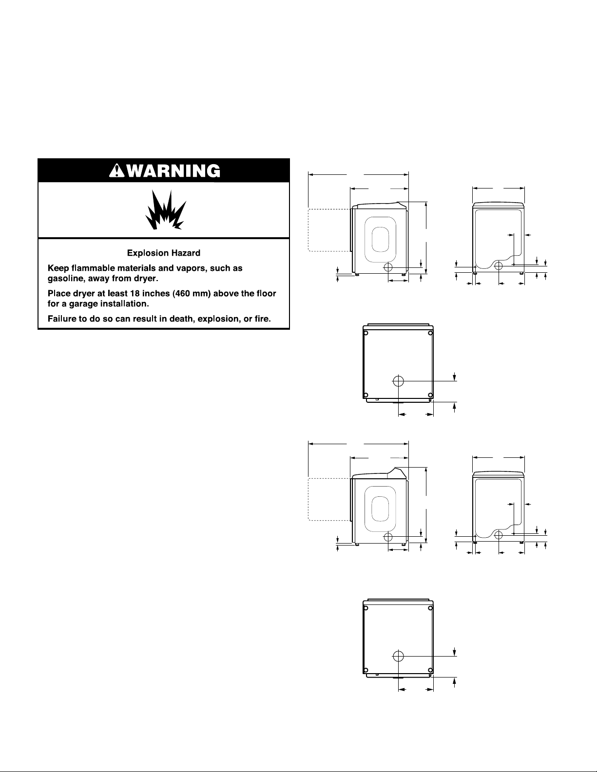
DRYER DIMENSIONS
Front Controls Models
5
57
/8"
(1464 mm)
331/2"
(851 mm)
Door Opened
Door Closed
29"
(737 mm)
You will need:
■ A location allowing for proper exhaust installation.
See “Venting Requirements.”
■ A separate 15 or 20-amp circuit needed for gas dryers and
30-amp circuit needed for electric dryers.
■ If using power supply cord, a grounded electrical outlet
located within 2 ft. (610 mm) of either side of dryer.
See “Electrical Requirements.”
■ Floor must support dryer weight of 200 lbs. (90.7 kg).
Also consider weight of companion appliance.
■ Level oor with maximum slope of 1" (25 mm) under entire
dryer. If slope is greater than 1" (25 mm), clothes may not
tumble properly and automatic sensor cycles may not
operate correctly.
■ For garage installation, place dryer at least 18" (460 mm)
above oor.
■ Steam models only: Cold water faucets located within 4 ft.
(1.2 m) of the water ll valves, and water pressure of 20-100
psi (137.9-689.6 kPa). You may use the water supply for your
washer using the “Y” connector and short hose which are
provided.
IMPORTANT: Do not operate, install, or store dryer where
it will be exposed to water, weather, or at temperatures below
45°F (7°C). Lower temperatures may cause dryer not to
shut off at end of automatic sensor cycles, resulting in longer
drying times.
NOTE: No other fuel-burning appliance can be installed in the
same closet as a dryer.
1"
(25 mm)
Side view
Bottom view:
Rear Controls Models
5
57
/8"
(1464 mm)
1"
(25 mm)
Bottom view:
331/2"
(851 mm)
3
11
/8"
(289 mm)
(365 mm)
3
11
/8"
(289 mm)
413/8"
(1050 mm)
5
3
/8"
(93 mm)
3
14
/8"
Door Opened
Door Closed
4111/16"
43 716"
(1103 mm)
(1103 mm)
5
3
/8"
(93 mm)
3"
(77 mm)
81/2"
(218 mm)
3"
(77 mm)
13/8"
(370 mm)
(35 mm)
Back view
29"
(737 mm)
13/8"
(370 mm)
(35 mm)
Back viewSide view
57/8"
(150 mm)
1
4
/2"
(115 mm)
1
/2"
14
1
/2"
14
3
(93 mm)
57/8"
(150 mm)
1
4
/2"
(115 mm)
3
(93 mm)
1
/2"
1
/2"
81/2"
(218 mm)
3
14
/8"
(365 mm)
NOTE: Most installations require a minimum of 6" (152 mm)
clearance behind dryer for exhaust vent with elbow. See
“Venting Requirements.”
5
Page 6
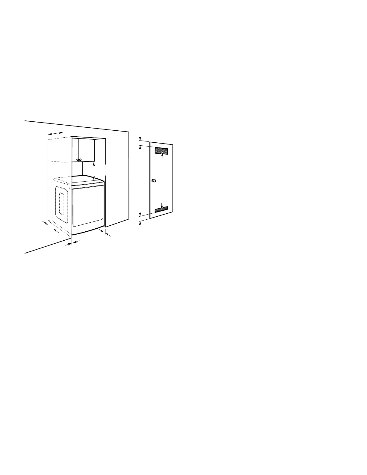
Spacing for recessed area or closet installation
The dimensions shown are for the recommended spacing
allowed.
■ Additional spacing should be considered for ease of
installation and servicing.
■ Additional clearances might be required for wall, door,
and oor moldings.
■ Additional spacing of 1" (25 mm) on all sides of the
dryer is recommended to reduce noise transfer.
■ For closet installation, with a door, minimum ventilation
openings in the top and bottom of the door are required.
Louvered doors with equivalent ventilitation openings
are acceptable.
■ Companion appliance spacing should also be considered.
14" max
(356 mm)
3"/3"
18"/18"*
(457 mm)
(76 mm)
3"/3"
(76 mm)
2
48 in./48 in.
48"
(310 cm2)
2/
24 in./24 in.
24"
(155 cm2)
/48"
24"
ELECTRICAL REQUIREMENTS -
U.S.A. ONLY (SPÉCIFICATIONS
ÉLECTRIQUES – ÉTATS-UNIS
SEULEMENT)
It is your responsibility:
■ To contact a qualied electrical installer.
■ To be sure that the electrical connection is adequate and in
conformance with the National Electrical Code, ANSI/NFPA
70 - latest edition and all local codes and ordinances.
The National Electrical Code requires a 4-wire power supply
connection for homes built after 1996, dryer circuits involved
in remodeling after 1996, and all mobile home installations.
A copy of the above code standards can be obtained from:
National Fire Protection Association, One Batterymarch Park,
Quincy, MA 02269.
■ To supply the required 3- or 4-wire, single phase, 120/240
2
2
volt, 60 Hz, AC only electrical supply (or 3- or 4-wire,
120/208 volt electrical supply, if specied on the serial/rating
plate) on a separate 30-amp circuit, fused on both sides of
the line. Connect to an individual branch circuit. Do not have
a fuse in the neutral or grounding circuit.
■ Do not use an extension cord.
■ If codes permit and a separate ground wire is used, it is
recommended that a qualied electrician determine that
the ground path is adequate.
6"/0"
(152 mm/0 mm)
1"/0"
(25 mm/0 mm)
1"/1"
(25 mm)
Recommended/Minimum spacing
Mobile home - Additional installation requirements:
This dryer is suitable for mobile home installations.
The installation must conform to the Manufactured
Home Construction and Safety Standard, Title 24 CFR,
Part 3280 (formerly the Federal Standard for Mobile home
construction and Safety, Title 24, HUD Part 280) or Standard
CAN/CSA-Z240 MH.
Mobile home installations require:
All dryers:
■ Metal exhaust system hardware, available for purchase
from your dealer. For further information, see “Assistance
or Service” section in your “Use and Care Guide.”
■ Special provisions must be made in mobile homes to
introduce outside air into dryer. Openings (such as a
nearby window) should be at least twice as large as
dryer exhaust opening.
For gas dryers mobile home installations:
■ Mobile Home Installation Hold-down Kit is available to order.
For further information, see “Assistance or Service” section
in your “Use and Care Guide.”
6
Electrical Connection
To properly install your dryer, you must determine the type of
electrical connection you will be using and follow the instructions
provided for it here.
■ This dryer is manufactured ready to install with a 3-wire
electrical supply connection. The neutral ground conductor
is permanently connected to the neutral conductor (white
wire) within the dryer. If the dryer is installed with a 4-wire
electrical supply connection, the neutral ground conductor
must be removed from the external ground connector (green
screw), and secured under the neutral terminal (center or
white wire) of the terminal block. When the neutral ground
conductor is secured under the neutral terminal (center or
white wire) of the terminal block, the dryer cabinet is isolated
from the neutral conductor.
■ If local codes do not permit the connection of a neutral
ground wire to the neutral wire, see “Optional 3-wire
connection” section.
■ A 4-wire power supply connection must be used when the
appliance is installed in a location where grounding through
the neutral conductor is prohibited. Grounding through the
neutral is prohibited for (1) new branch-circuit installations,
(2) mobile homes, (3) recreational vehicles, and (4) areas
where local codes prohibit grounding through the neutral
conductors.
If using a power supply cord:
Use a UL listed power supply cord kit marked for use with
clothes dryers. The kit should contain:
■ A UL listed 30-amp power supply cord, rated 120/240
volt minimum, with a temperature rating of 140°F (60°C)
minimum. The cord should be type SRD or SRDT, and
be at least 4 ft. (1.22 m) long. The wires that connect to
the dryer must end in ring terminals or spade terminals
with upturned ends.
■ A UL listed strain relief.
Page 7
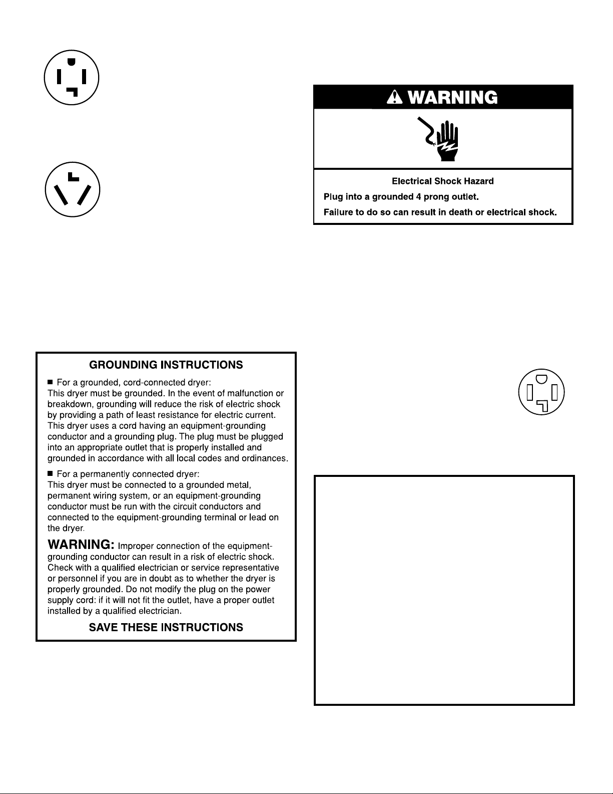
If your outlet looks like this:
Then choose a 4-wire power supply cord with
ring or spade terminals and UL listed strain
relief. The 4-wire power supply cord, at least
4 ft. (1.22 m) long, must have 4 10-gauge solid
copper wires and match a 4-wire receptacle of
4-wire
receptacle
(14-30R)
NEMA Type 14-30 R. The ground wire (ground
conductor) may be either green or bare. The
neutral conductor must be identied by a
white cover.
If your outlet looks like this:
Then choose a 3-wire power supply cord with
ring or spade terminals and UL listed strain
relief. The 3-wire power supply cord, at least
4 ft. (1.22 m) long, must have 3 10-gauge solid
copper wires and match a 3-wire receptacle of
3-wire
receptacle
(10-30R)
NEMA Type 10-30R.
If connecting by direct wire:
Power supply cable must match power supply (4-wire or 3-wire)
and be:
■ Flexible armored cable or nonmetallic sheathed copper
cable (with ground wire), covered with exible metallic
conduit. All current-carrying wires must be insulated.
■ 10-gauge solid copper wire (do not use aluminum) at
least 5 ft. (1.52 m) long.
ELECTRIC DRYER POWER HOOKUPCANADA ONLY
ELECTRICAL REQUIREMENTS
It is your responsibility:
■ To contact a qualied electrical installer.
■ To be sure that the electrical connection is adequate and in
conformance with Canadian Electrical Code, C22.1-latest
edition and all local codes. A copy of above codes standard
may be obtained from: Canadian Standards Association,
178 Rexdale Blvd., Toronto, ON M9W 1R3 CANADA.
■ To supply the required 4-wire, single phase, 120/240 volt,
60 Hz, AC only electrical supply on a separate 30-amp
circuit, fused on both sides of the line. A time-delay fuse or
circuit breaker is recommended. Connect to an individual
branch circuit.
■ This dryer is equipped with a CSA
International Certied Power Cord
intended to be plugged into a standard
14-30R wall receptacle. The cord is
5 ft. (1.52 m) long. Be sure wall receptacle
is within reach of dryer’s nal location.
4-wire receptacle
(14-30R)
For further information, please reference service numbers located
in “Assistance or Service” section of your “Use and Care Guide.”
GROUNDING INSTRUCTIONS
■
For a grounded, cord-connected dryer:
This dryer must be grounded. In the event of malfunction or
breakdown, grounding will reduce the risk of electric shock
by providing a path of least resistance for electric current.
This dryer is equipped with a cord having an equipmentgrounding conductor and a grounding plug. The plug must
be plugged into an appropriate outlet that is properly
installed and grounded in accordance with all local codes
and ordinances.
WARNING: Improper connection of the equipment-
grounding conductor can result in a risk of electric shock.
Check with a qualied electrician or service representative
or personnel if you are in doubt as to whether the dryer is
properly grounded. Do not modify the plug provided with
the dryer: if it will not t the outlet, have a proper outlet
installed by a qualied electrician.
SAVE THESE INSTRUCTIONS
7
Page 8
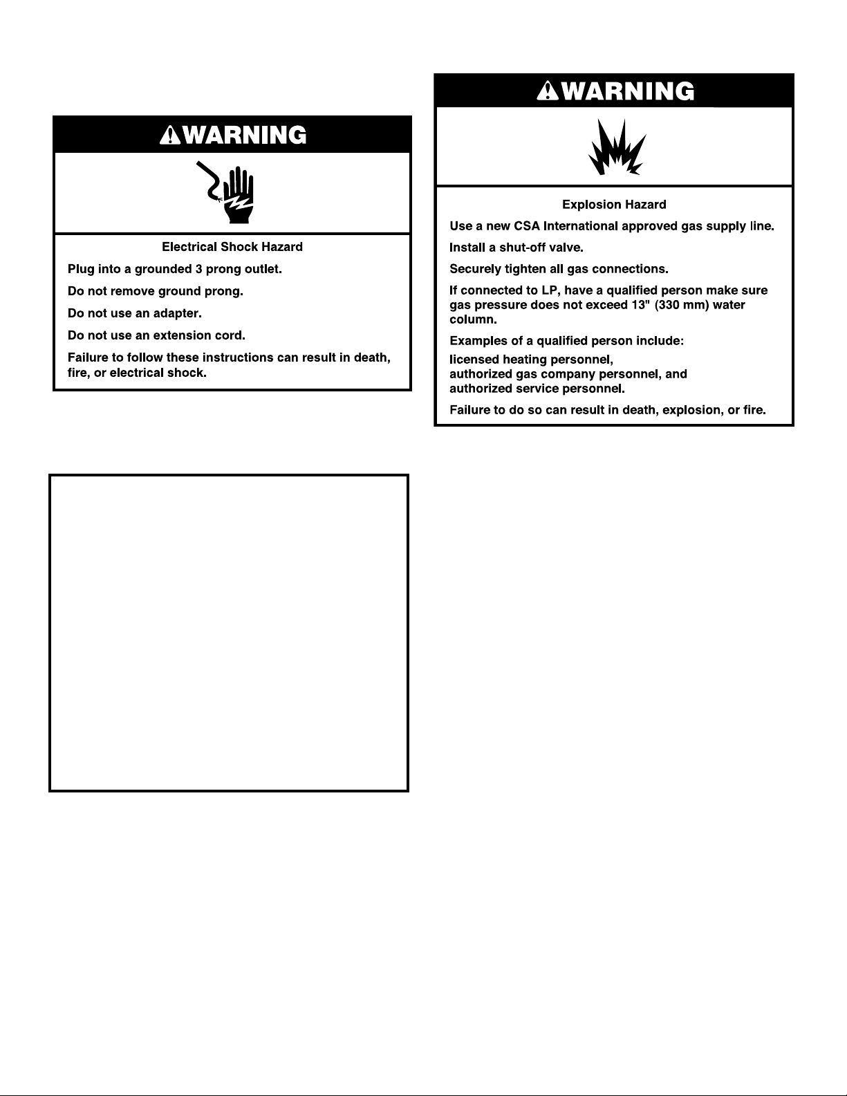
GAS DRYER POWER HOOKUP -
U.S.A. AND CANADA
ELECTRICAL REQUIREMENTS
■ 120 Volt, 60 Hz, AC only, 15- or 20- amp fused electrical
supply is required. A time-delay fuse or circuit breaker is
recommended. It is also recommended that a separate
circuit serving only this dryer be provided.
GROUNDING INSTRUCTIONS
■
For a grounded, cord-connected dryer:
This dryer must be grounded. In the event of malfunction or
breakdown, grounding will reduce the risk of electric shock
by providing a path of least resistance for electric current.
This dryer is equipped with a cord having an equipmentgrounding conductor and a grounding plug. The plug must
be plugged into an appropriate outlet that is properly
installed and grounded in accordance with all local codes
and ordinances.
WARNING: Improper connection of the equipment-
grounding conductor can result in a risk of electric shock.
Check with a qualied electrician or service representative
or personnel if you are in doubt as to whether the dryer is
properly grounded. Do not modify the plug provided with
the dryer: if it will not t the outlet, have a proper outlet
installed by a qualied electrician.
SAVE THESE INSTRUCTIONS
GAS SUPPLY REQUIREMENTS
GAS TYPE
Natural Gas:
This dryer is equipped for use with Natural gas. It is designcertied by CSA International for LP (propane or butane) gases
with appropriate conversion.
■ Your dryer must have the correct burner for the type of gas
in your home. Burner information is located on the rating
plate in the door well of your dryer. If this information does
not agree with the type of gas available, contact your dealer
or call the phone numbers referenced in the “Assistance or
Service” section of your “Use and Care Guide.”
LP Gas Conversion:
IMPORTANT: Conversion must be made by a qualied
technician.
No attempt shall be made to convert the dryer from the gas
specied on the model/serial rating plate for use with a
different gas without consulting your gas company.
GAS SUPPLY LINE
Option 1 (Recommended Method)
Flexible stainless steel gas connector:
■ If local codes permit, use a new exible stainless steel gas
connector (Design Certied by the American Gas Association
or CSA International) to connect your dryer to the rigid
gas supply line. Use an elbow and a 3/8" are x 3/8" NPT
adapter tting between the stainless steel gas connector and
the dryer gas pipe as needed to prevent kinking.
Option 2 (Alternate Method)
Approved aluminum or copper tubing
■ Must include 1/8" NPT minimum plugged tapping accessible
for test gauge connection, immediately upstream of the gas
connection to the dryer.
■ 1/2" IPS pipe is recommended.
■ 3/8" approved aluminum or copper tubing is acceptable for
lengths under 20 ft. (6.1 m) if local codes and gas supplier
permit.
■ If you are using Natural gas, do not use copper tubing.
8
Page 9
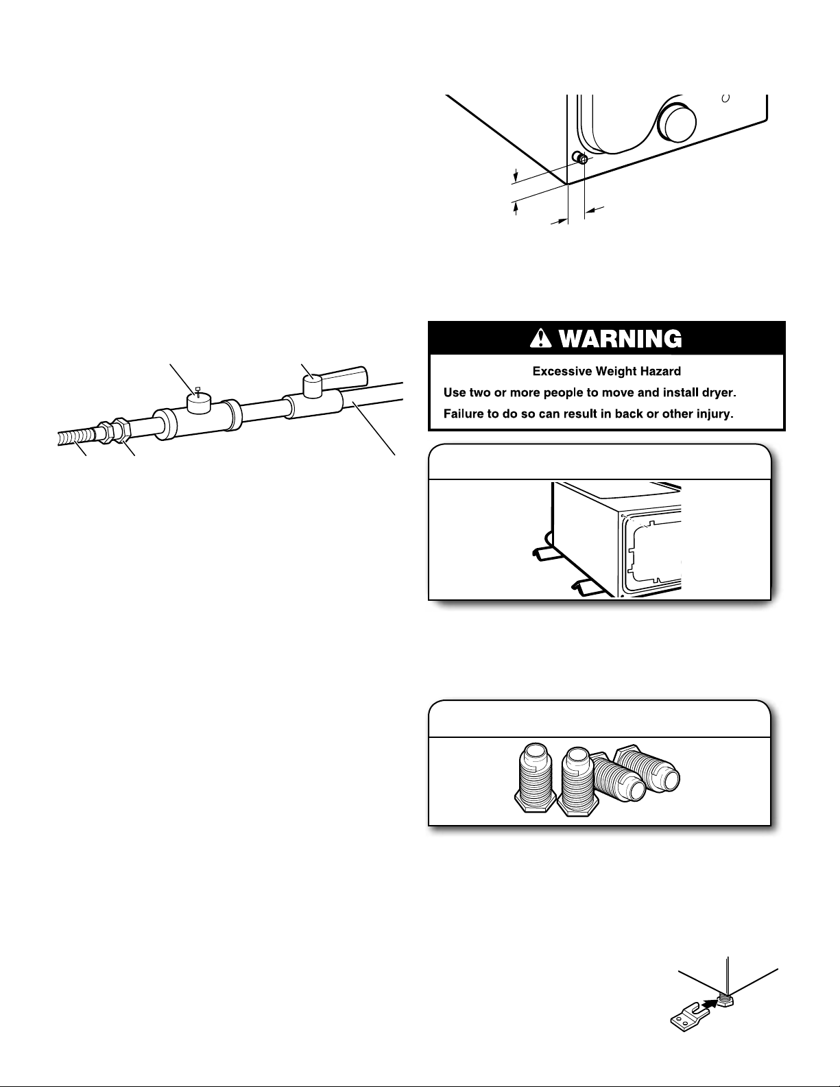
Lengths over 20 ft. (6.1 m) should use larger tubing and
■
a different size adapter tting.
■ If your dryer has been converted to use LP gas, 3/8" LP
compatible copper tubing can be used. If the total length of
the supply line is more than 20 ft. (6.1 m), use larger pipe.
NOTE: Pipe-joint compounds that resist the action of
LP gas must be used. Do not use TEFLON
■ Must include shut-off valve
In the U.S.A.:
An individual manual shut-off valve must be installed within
six (6) ft. (1.8 m) of the dryer in accordance with the National
Fuel Gas Code, ANSI Z223.1. The location should be easy to
reach for opening and closing.
In Canada:
An individual manual shut-off valve must be installed in
accordance with the B149.1, Natural Gas and Propane
Installation Code. It is recommended that an individual
manual shutoff valve be installed within six (6) ft. (1.8 m) of
the dryer. The location should be easy to reach for opening
and closing.
C
®†
tape.
E
DRYER GAS PIPE
■ The gas pipe that comes out through the rear of your dryer
has a 3/8" male pipe thread.
3
/8"
1
3"
(77 mm)
3/8" NPT dryer pipe
NOTE: For a garage installation, the gas pipe height must be an
additional 18" (460 mm) from the oor.
(35 mm)
INSTALL LEVELING LEGS
BA
A. 3/8" exible gas connector
B. 3/8" pipe to are adapter tting
C. 1/8" NPT minimum plugged tapping
D. 1/2" NPT gas supply line
E. Gas shutoff valve.
GAS SUPPLY CONNECTION REQUIREMENTS
■ Use an elbow and a 3/8" are x 3/8" NPT adapter tting
between the exible gas connector and the dryer gas pipe,
as needed to avoid kinking.
■ Use only pipe-joint compound. Do not use TEFLON
■ This dryer must be connected to the gas supply line with a
listed exible gas connector that complies with the standard
for connectors for gas appliances, ANSI Z21.24 or CSA 6.10.
®†
tape.
BURNER INPUT REQUIREMENTS
Elevations above 2,000 ft. (610 m):
■ When installed above 2,000 ft. (610 m) a 4% reduction of the
burner Btu rating shown on the model/serial number plate is
required for each 1,000 ft. (305 m) increase in elevation.
Gas supply pressure testing
■ The dryer must be disconnected from the gas supply piping
system during pressure testing at pressures greater than
1/2 psi.
†®TEFLON is a registered trademark of E.I. Dupont De Nemours and Company.
D
Firmly grasp dryer body (not console panel) and gently lay
dryer down on back cardboard corner posts.
IMPORTANT: If laying dryer on its back, use the cardboard
corner posts the dryer was packed with to avoid damaging
the back of the dryer.
Using a wrench and tape measure, screw leveling legs into
leg holes until bottom of foot is approximately 1" (25 mm)
from bottom of dryer.
Now stand the dryer on its feet. Slide the dryer until it is
close to its nal location. Leave enough room to connect
the exhaust vent.
Prepare dryer for leveling legs
1.
Screw in leveling legs
2.
For mobile home use
Gas dryers must be securely fastened to the oor.
Mobile home installations require a Mobile
Home Installation Hold-down Kit. For
ordering information please reference
the “Use and Care Guide.”
9
Page 10
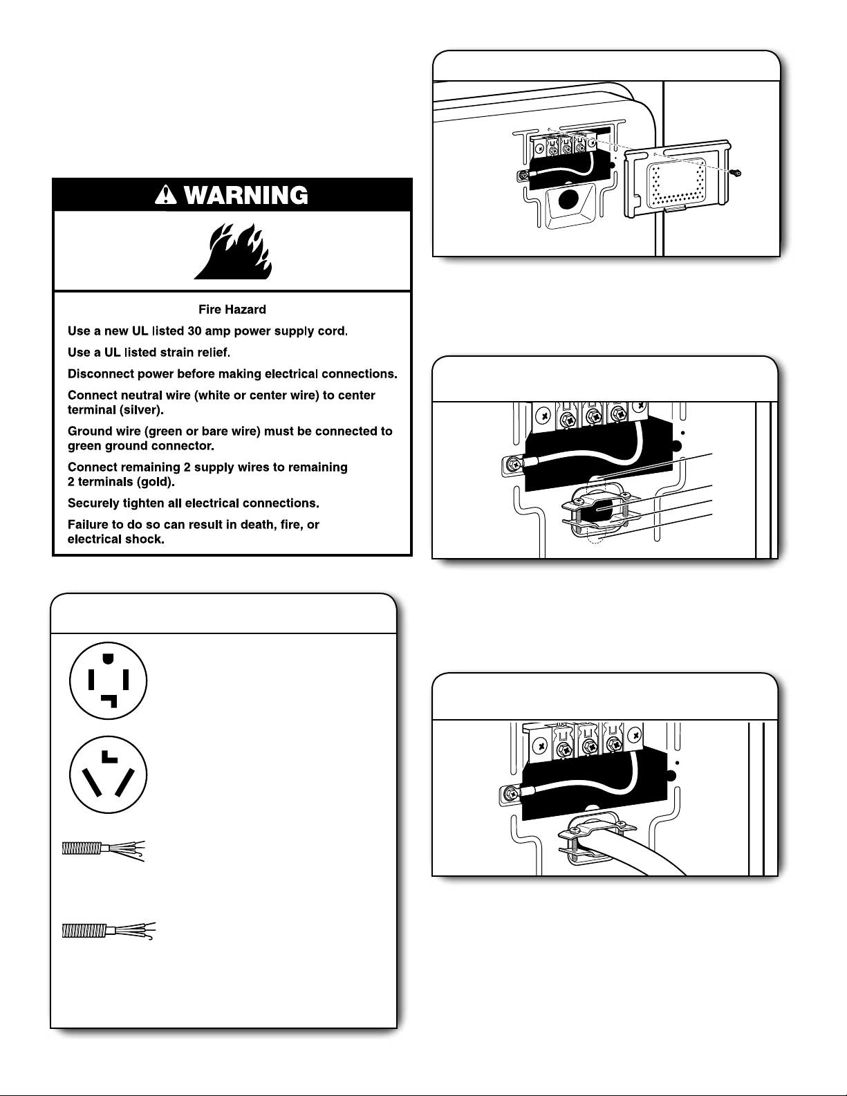
MAKE ELECTRICAL CONNECTION -
U.S.A. ONLY (EFFECTUER LE
RACCORDEMENT ÉLECTRIQUE –
ÉTATS-UNIS SEULEMENT)
ELECTRICAL CONNECTION
Power Supply Cord
2. Remove terminal block cover
Remove hold-down screw and terminal block cover.
POWER SUPPLY CORD CONNECTION
Power Supply Cord Strain Relief
Attach power supply cord
1.
strain relief
A
Electrical Connection Options
1. Choose electrical connection type
Power supply cord 4-wire receptacle
(NEMA Type 14-30R):
Go to Power Supply Cord Connection.
Power supply cord 3-wire receptacle
(NEMA Type 10-30R):
Go to Power Supply Cord Connection.
4-wire direct connection:
Go to Direct Wire Connection.
B
C
D
Remove the screws from a 3/4" (19 mm) UL listed strain relief
(UL marking on strain relief). Put the tabs of the two clamp
sections (C) into the hole below the terminal block opening
(B) so that one tab is pointing up (A) and the other is pointing
down (D), and hold in place. Tighten strain relief screws just
enough to hold the two clamp sections (C) together.
2.
Attach power supply cord
to strain relief
3-wire direct connection:
Go to Direct Wire Connection.
NOTE: If local codes do not permit connection of a
cabinet-ground conductor to neutral wire, go to “Optional
3-wire connection.” This connection may be used with
either a power supply cord or a direct wire connection.
10
Put power supply cord through the strain relief. Be sure that
the wire insulation on the power supply cord is inside the
strain relief. The strain relief should have a tight t with the
dryer cabinet and be in a horizontal position. Do not further
tighten strain relief screws at this point.
Page 11
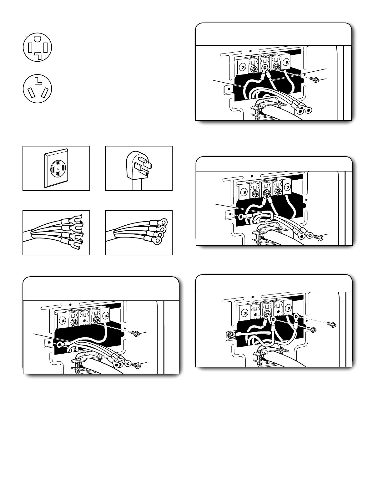
If your outlet looks like this:
Power supply cord 4-wire receptacle
(NEMA Type 14-30R):
Go to “4-Wire Power Supply Cord
Connection”.
Power supply cord 3-wire receptacle
(NEMA Type 10-30R):
Go to “3-Wire Power Supply Cord
Connection”.
4-wire Power Supply Cord Connection
2.
Connect neutral ground wire
and neutral wire
C
E
B
IMPORTANT: A 4-wire connection is required for mobile homes and
where local codes do not permit the use of 3-wire connections.
4-wire receptacle (NEMA
type 14-30R)
Spade terminals with
upturned ends
Prepare to connect neutral
1.
4-prong plug
Ring terminals
ground wire and neutral wire
Connect neutral ground wire (E) and neutral wire (white) (C)
of power supply cord under center terminal block screw (B).
Tighten screw.
3. Connect ground wire
F
A
Connect ground wire (F) (green or bare) of power supply cord
to external ground conductor screw (A). Tighten screw.
4.
Connect remaining wires
E
Remove center terminal block screw (B). Remove neutral
ground wire (E) from external ground conductor screw (A).
Reinstall ground conductor screw (A).
B
A
Connect remaining wires to outer terminal block screws.
Tighten screws. Finally, reinsert tab of terminal block cover
into slot of dryer rear panel. Secure cover with hold-down
screw. Now, go to “Venting Requirements.”
11
Page 12
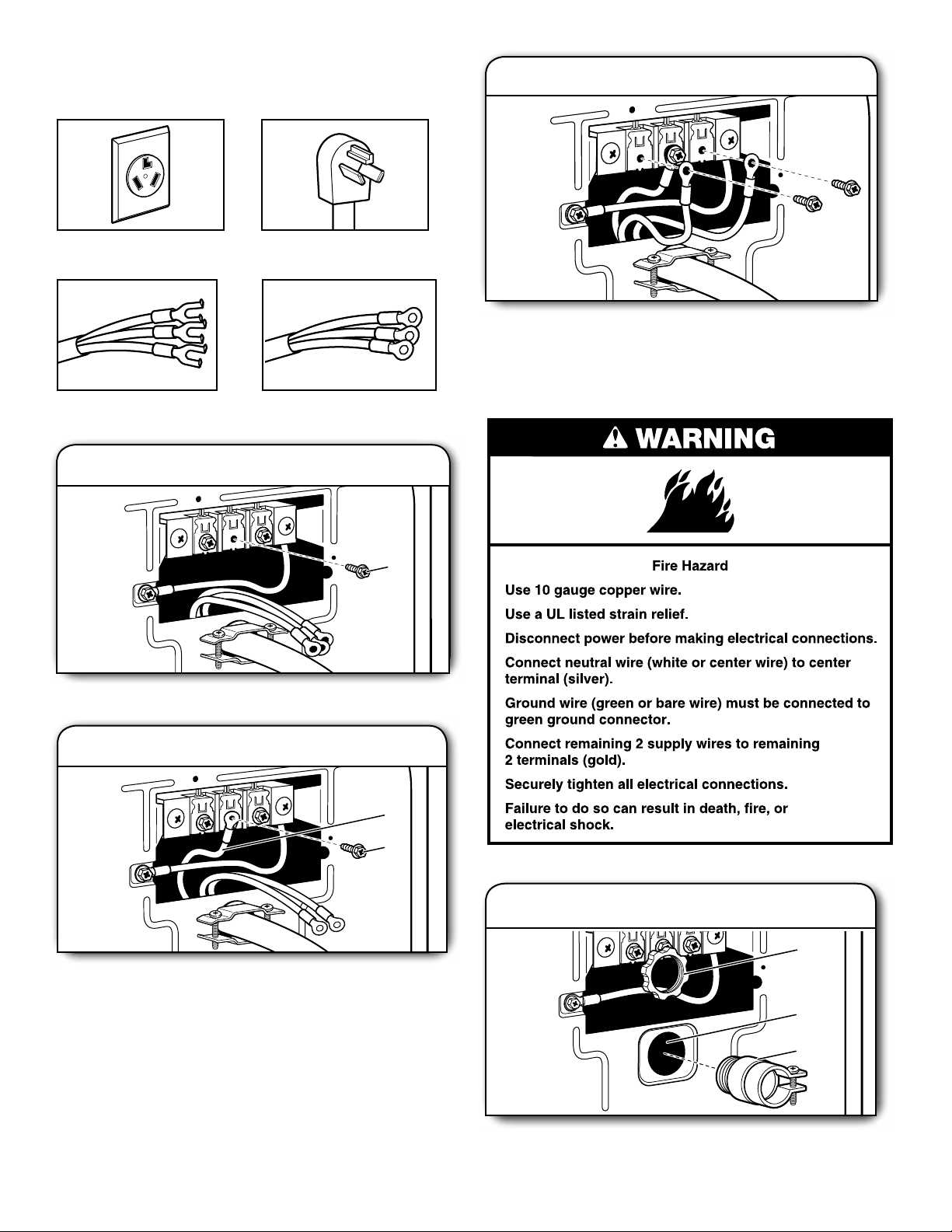
3-wire Power Supply Cord Connection
Use where local codes permit connecting cabinet-ground
conductor to neutral wire.
3. Connect remaining wires
3-wire receptacle (NEMA
type 10-30R)
Spade terminals with
upturned ends
3-prong plug
Ring terminals
1. Remove center screw
Connect remaining wires to outer terminal block screws.
Tighten screws. Finally, reinsert tab of terminal block cover
into slot of dryer rear panel. Secure cover with hold-down
screw. Now, go to “Venting Requirements.”
DIRECT WIRE CONNECTION
B
Remove center terminal block screw (B).
2. Connect neutral wire
C
B
Connect neutral wire (white or center) (C) of power supply cord
to center terminal block screw (B). Tighten screw.
Direct Wire Strain Relief
1. Attach direct wire strain relief
A
B
C
Unscrew the removable conduit connector (A) and any
screws from a 3/4" (19 mm) UL listed strain relief (UL marking
12
Page 13
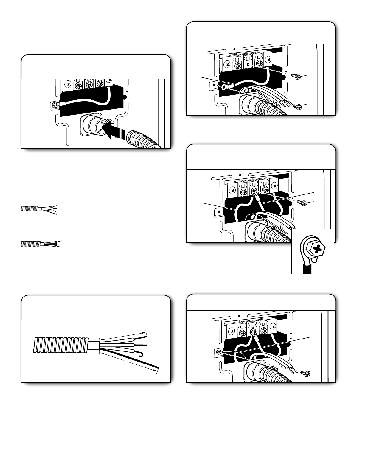
on strain relief). Put the threaded section of the strain relief
(C) through the hole below the terminal block opening (B).
Reaching inside the terminal block opening, screw the
removable conduit connector (A) onto the strain relief threads.
2. Attach direct wire cable
to strain relief
2. Prepare to connect neutral
ground wire and neutral wire
E
Remove center terminal block screw (B). Remove neutral
ground wire (E) from external ground conductor screw (A).
B
A
Put direct wire cable through the strain relief. The strain
relief should have a tight t with the dryer cabinet and be in
a horizontal position. Tighten strain relief screw against the
direct wire cable.
If your wiring looks like this:
4-wire direct connection:
Go to “4-Wire Direct Connection”
on this page.
3-wire direct connection:
Go to “3-Wire Direct Connection”
on page 11.
4-wire Direct Wire Connection
IMPORTANT: A 4-wire connection is required for mobile
homes and where local codes do not permit 3-wire
connections.
1. Prepare your 4-wire cable for
direct connection
3. Connect neutral ground wire
and neutral wire
C
Connect neutral ground wire (E) and place
hooked end (hook facing right) of neutral
wire (white or center wire) (C) of direct wire
cable under center screw of terminal block
(B). Squeeze hooked ends together and
tighten screw.
4. Connect ground wire
E
B
3½"
(89 mm)
5"
(127 mm)
Direct wire cable must have 5 ft. (1.52 m) of extra length
so dryer may be moved if needed.
Strip 5" (127 mm) of outer covering from end of cable,
leaving bare ground wire at 5" (127 mm). Cut 1
from remaining 3 wires. Strip insulation back 1" (25 mm).
Shape ends of wires into hooks.
1
/2" (38 mm)
F
A
Connect ground wire (green or bare) (F) of direct wire cable
to external ground conductor screw (A). Tighten screw.
13
Page 14
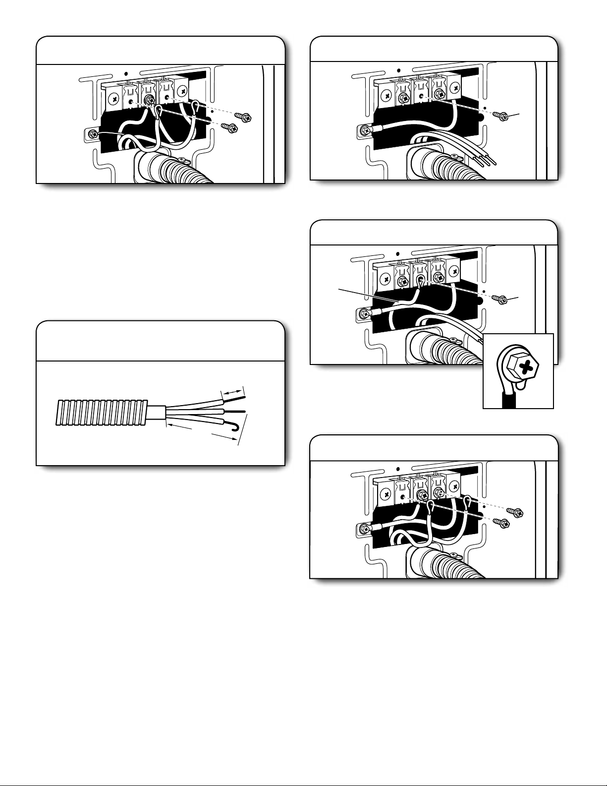
5. Connect remaining wires
2. Remove center screw
B
Place hooked ends of remaining direct wire cable wires
under outer terminal block screws (hooks facing right).
Squeeze hooked ends together and tighten screws. Finally,
reinsert tab of terminal block cover into slot of dryer rear
panel. Secure cover with hold-down screw. Now, go to
“Venting Requirements.”
3-wire Direct Wire Connection
Use where local codes permit connecting cabinet-ground
conductor to neutral wire.
1. Prepare your 3-wire cable for
direct connection
1"
(25 mm)
3½"
(89 mm)
Direct wire cable must have 5 ft. (1.52 m) of extra length so
dryer may be moved if needed.
1
Strip 3
/2" (89 mm) of outer covering from end of cable. Strip
insulation back 1" (25 mm). If using 3-wire cable with ground
wire, cut bare wire even with outer covering. Shape wire ends
into hooks.
Remove center terminal block screw (B).
3. Connect neutral wire
C
Place hooked end of neutral wire (white
or center) (C) of direct wire cable under
center terminal block screw (B). Squeeze
hooked end together. Tighten screw.
4.
Connect remaining wires
B
14
Place hooked ends of remaining direct wire cable wires
under outer terminal block screws (hooks facing right).
Squeeze hooked ends together and tighten screws. Finally,
reinsert tab of terminal block cover into slot of dryer rear
panel. Secure cover with hold-down screw. Now, go to
“Venting Requirements.”
Page 15
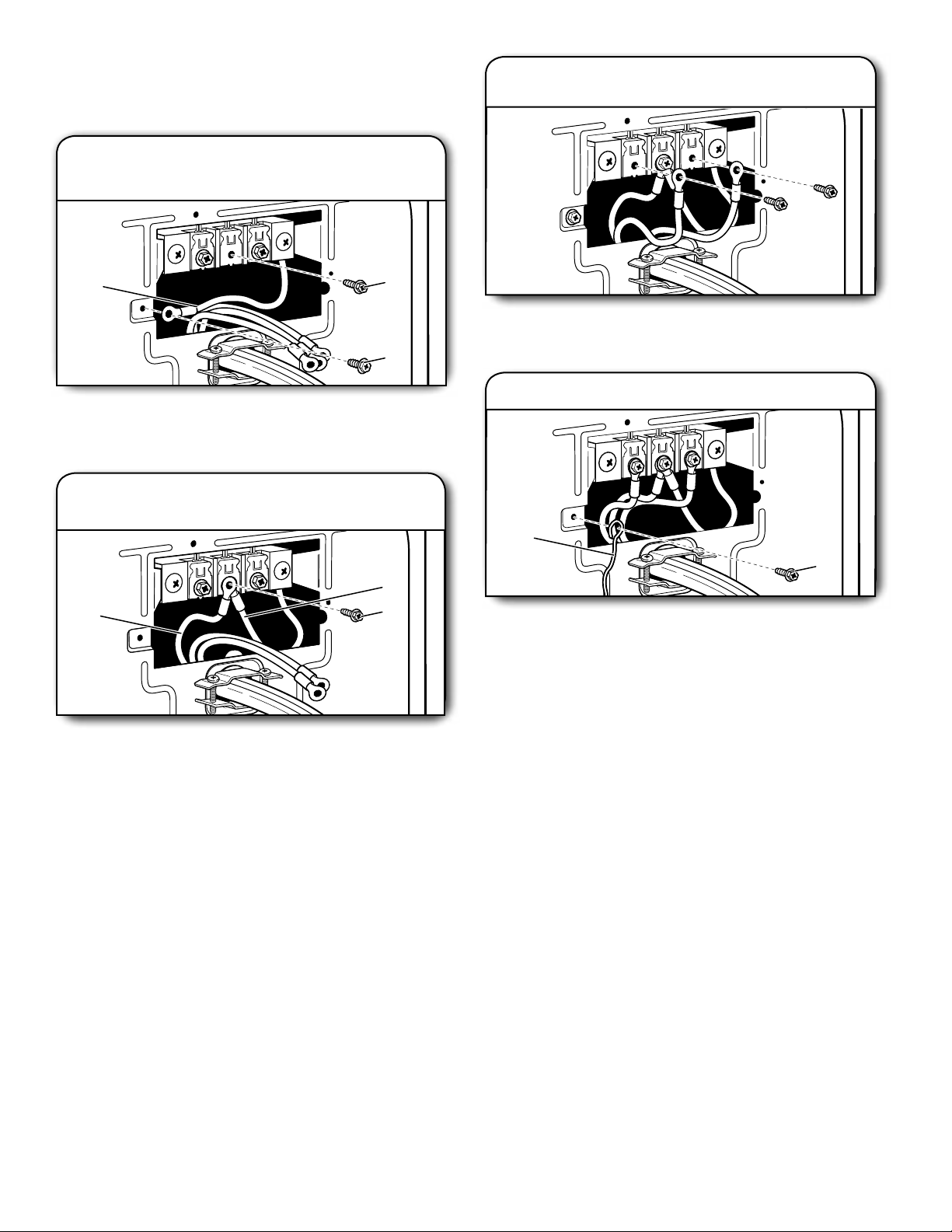
Optional 3-wire Connection
A
G
You must verify with a qualied electrician that this grounding
method is acceptable before connecting.
1. Prepare to connect neutral
ground wire and neutral wire
3.
Connect remaining wires
E
Remove center terminal block screw (B). Remove neutral
ground wire (E) from external ground conductor screw (A).
2.
Connect neutral ground wire
B
A
and neutral wire
E
C
B
Connect remaining wires to outer terminal block screws
Tighten screws.
4.
Connect external ground wire
Connect a separate copper ground wire (G) from the external
ground conductor screw (A) to an adequate ground. Finally,
reinsert tab of terminal block cover into slot of dryer rear
panel. Secure cover with hold-down screw. Now, go to
“Venting Requirements.”
Connect neutral ground wire (E) and neutral wire (white or
center wire) (C) of power supply cord or cable under center
terminal block screw (B). Tighten screw.
15
Page 16
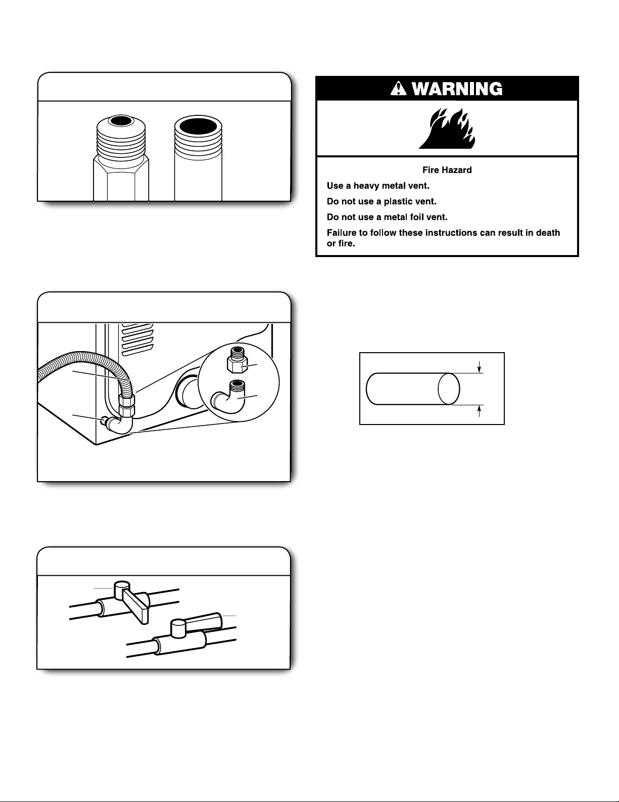
A
B
A
B
B
A
D
C
MAKE GAS CONNECTION -
U.S.A. AND CANADA
VENTING
VENTING REQUIREMENTS
1.
male tting
Remove red cap from gas pipe. Using a wrench to tighten,
connect gas supply to dryer. Use pipe-joint compound
on threads of all non-ared male ttings. If exible metal
tubing is used, be sure there are no kinks.
NOTE: For LP gas connections, you must use pipe-joint
compound resistant to action of LP gas. Do not use
TEFLON
2.
Connect gas supply to dryer
Flared
®†
tape.
Plan pipe tting connection
Non-ared
male tting
WARNING: To reduce the risk of re, this dryer MUST BE
EXHAUSTED OUTDOORS.
IMPORTANT: Observe all governing codes and ordinances.
Dryer exhaust must not be connected into any gas vent,
chimney, wall, ceiling, attic, crawlspace, or a concealed space
of a building. Only rigid or exible metal vent shall be used for
exhausting.
A. 3/8" exible gas connector
B. 3/8" dryer pipe
A combination of pipe ttings must be used to connect dryer
to existing gas line. Recommended connection is shown.
Your connection may be different, according to supply line
type, size, and location.
3.
Closed valve
Open shut-off valve in supply line; valve is open when handle
is parallel to gas pipe. Then, test all connections by brushing
on an approved noncorrosive leak-detection solution.
Bubbles will show a leak. Correct any leaks found.
16
Open shut-off valve
C. 3/8" to 3/8" pipe elbow
D. 3/8" pipe-to-are adapter tting
Open valve
4"
(102 mm)
4" (102 mm) heavy metal exhaust vent
■ Only a 4" (102 mm) heavy metal exhaust vent and clamps
may be used.
■ Do not use plastic or metal foil vent.
Rigid metal vent:
■ Recommended for best drying performance and to avoid
crushing and kinking.
Flexible metal vent: (Acceptable only if accessible to clean)
■ Must be fully extended and supported in nal dryer location.
■ Remove excess to avoid sagging and kinking that may
result in reduced airow and poor performance.
■ Do not install in enclosed walls, ceilings, or oors.
■ The total length should not exceed 7
■ The length of exible metal vent used must be included in
the overall vent system design as shown in the “Vent
System Charts.”
3
/4 ft. (2.4 m).
NOTE: If using an existing vent system, clean lint from
entire length of the system and make sure exhaust hood
is not plugged with lint. Replace plastic or metal foil vents
with rigid metal or exible metal vents. Review Vent System
Chart and, if necessary, modify existing vent system to
achieve best drying performance.
Page 17
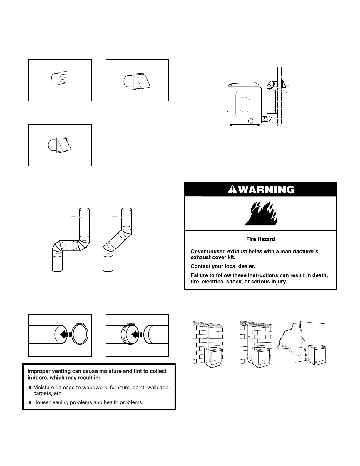
Exhaust hoods:
■ Must be at least 12" (305 mm) from ground or any object
that may obstruct exhaust (such as owers, rocks, bushes,
or snow).
Recommended Styles:
Louvered Hood
Box Hood
Acceptable Style:
PLAN VENT SYSTEM
Recommended exhaust installations
Typical installations vent the dryer from the rear of the dryer.
Other installations are possible.
B
C
D
A
E
F
G
B
H
Angled Hood
Elbows:
■ 45° elbows provide better airow than 90° elbows.
Recommended Styles:
Good
Better
Clamps:
■ Use clamps to seal all joints.
■ Exhaust vent must not be connected or secured with screws
or other fastening devices that extend into interior of duct
and catch lint. Do not use duct tape.
A. Dryer
B. Elbow
C. Wall
D. Exhaust hood
E. Clamps
F. Rigid metal or exible metal vent
G. Vent length necessary to connect elbows
H. Exhaust outlet
Optional exhaust installations:
If you prefer, dryer may be converted to exhaust through the
bottom and sides. You must contact your local dealer to have
dryer converted.
Vent products can be purchased from your dealer. For more
information, see “Assistance or Service” section in your “Use
and Care Guide.”
A
A. Standard rear offset exhaust installation
B. Left- or right-side exhaust installation
C. Bottom exhaust installation
B
C
17
Page 18
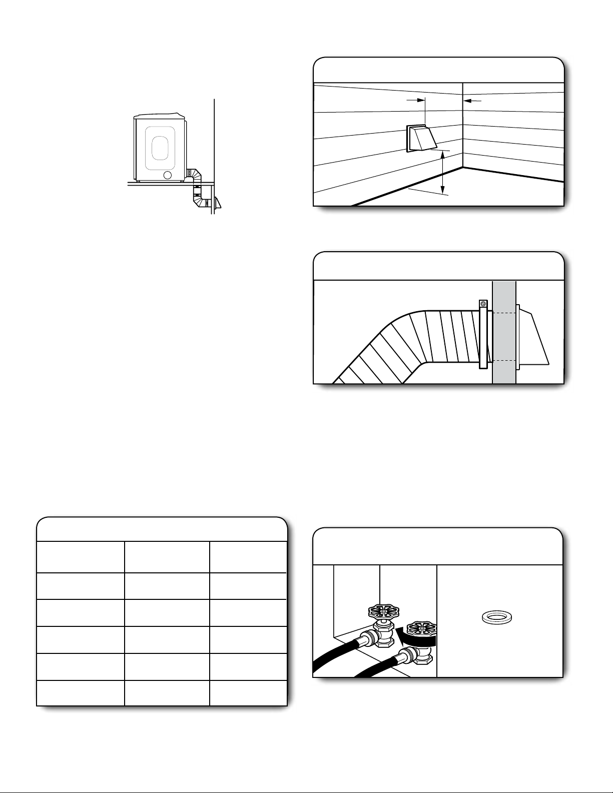
Special provisions for mobile homes:
12" min.
(305 mm)
12" min.
(305 mm)
Exhaust vent must be securely fastened to a noncombustible
portion of mobile home and must not terminate beneath the
mobile home. Terminate exhaust vent outside.
INSTALL VENT SYSTEM
1.
Install exhaust hood
Moblie Home Exhaust installation
Determine vent path:
■ Select route that will provide straightest and most direct
path outdoors.
■ Plan installation to use fewest number of elbows and turns.
■ When using elbows or making turns, allow as much room
as possible.
■ Bend vent gradually to avoid kinking.
■ Use as few 90° turns as possible.
Determine vent length and elbows needed for best
drying performance:
■ Use following Vent System Chart to determine type of vent
material and hood combinations acceptable to use.
NOTE: Do not use vent runs longer than those specied
in Vent System Chart. Exhaust systems longer than those
specied will:
■ Shorten life of dryer.
■ Reduce performance, resulting in longer drying times
and increased energy usage.
The Vent System Charts provide venting requirements that
will help achieve best drying performance.
Vent System Chart
Number of
90° elbows
Type of vent Angled
hoods
Install exhaust hood and use caulking compound to seal
exterior wall opening around exhaust hood.
2.
Connect vent to exhaust hood
Vent must t over the exhaust hood. Secure vent to exhaust
hood with 4" (102 mm) clamp. Run vent to dryer location
using straightest path possible. Avoid 90° turns. Use clamps
to seal all joints. Do not use duct tape, screws, or other
fastening devices that extend into interior of vent to secure
vent, because they can catch lint.
CONNECT INLET HOSES
For non-steam models, skip to “Connect Vent.”
The dryer must be connected to the cold water faucet using
the new inlet hoses. Do not use old hoses.
Turn cold water off, remove and
1.
replace rubber washer
0
1
2
3
4
NOTE: Bottom exhaust installations have a 90° turn inside the
dryer. To determine maximum exhaust length, add one 90° turn
to the charts.
18
Rigid metal
Rigid metal
Rigid metal
Rigid metal
Rigid metal
64 ft. (20 m)
54 ft. (16.5 m)
44 ft. (13.4 m)
35 ft. (10.7 m)
27 ft. (8.2 m)
Rubber washer
Turn cold water faucet off and remove washer inlet hose.
Remove old rubber washer from inlet hose and replace
with new rubber washer.
Page 19
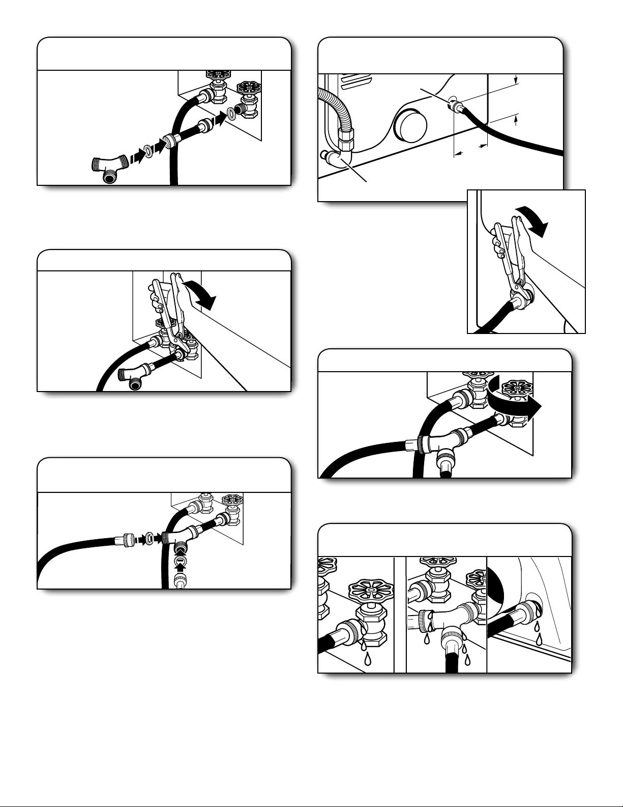
Attach short hose and
2.
“Y” connector
Attach 2 ft (0.6 m) inlet hose to cold water faucet. Screw on
coupling by hand until it is seated on faucet. Then attach “Y”
connector to male end of the 2 ft (0.6 m) inlet hose. Screw on
coupling by hand until it is seated on connector.
Tighten couplings
3.
Attach long hose to dryer ll
5.
valve and tighten coupling
Fill Valve
(150 mm)
Gas Valve
Attach other end of long hose
to ll valve at bottom of dryer
back panel. Screw on coupling
by hand until it is seated on ll
valve connector. Using pliers,
tighten the couplings an additional
two-thirds turn.
NOTE: Do not overtighten. Damage
to the coupling can result.
57/8"
1
4
/2"
(115 mm)
Using pliers, tighten the couplings with additional two-thirds
turn.
NOTE: Do not overtighten. Damage to the coupling can result.
Attach long hose to “Y”
4.
connector and tighten couplings
Attach dryer 5 ft (1.5 m) inlet hose ends to the “Y” connector.
Attach washer cold inlet hose to other side of “Y” connector.
Screw on coupling by hand until it is seated on connector.
Using pliers, tighten the couplings an additional two-thirds
turn.
NOTE: Do not overtighten. Damage to the coupling can result.
Turn on cold water faucet
6.
Check that the water faucet is turned on.
Check for leaks
7.
Check for leaks around “Y” connector, faucets, and hoses.
19
Page 20
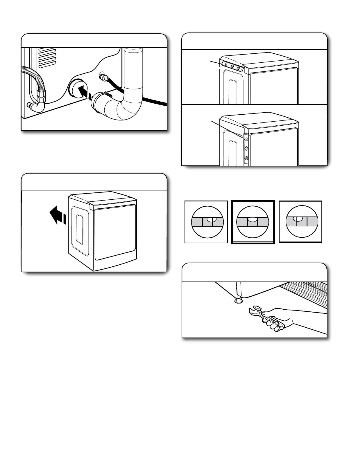
CONNECT VENT
1. Connect vent to exhaust outlet
Using a 4" (102 mm) clamp, connect vent to exhaust outlet
in dryer. If connecting to existing vent, make sure vent is
clean. Dryer vent must t over dryer exhaust outlet and inside
exhaust hood. Check that vent is secured to exhaust hood
with a 4" (102 mm) clamp.
2.
Move dryer to nal location
LEVEL DRYER
Level Dryer
1.
Place
level here
Place
level here
Check levelness of dryer from side to side. Repeat from
front to back.
NOTE: The dryer must be level for the moisture sensing
system to operate correctly.
Move dryer to nal location. Avoid crushing or kinking vent.
Not Level LEVEL Not Level
Adjust leveling legs
2.
If dryer is not level, prop up using a wood block. Use wrench
to adjust legs up or down, and check again for levelness.
20
Page 21

COMPLETE INSTALLATION
CHECKLIST
Check that all parts are now installed. If there is an extra
q
part, go back through steps to see what was skipped.
Check that you have all of your tools.
q
Dispose of/recycle all packaging materials.
q
Check dryer’s nal location. Be sure vent is not crushed
q
or kinked.
Check that dryer is level. See “Level Dryer.”
q
Remove lm on console and any tape remaining on dryer.
q
Wipe dryer drum interior thoroughly with a damp cloth to
q
remove any dust.
Read “Dryer Use” in your “Use and Care Guide.”
q
Electric Models:
For power supply cord installation, plug into a grounded
q
outlet. For direct wire installation, turn on Power.
Gas Models:
Check that gas supply is on.
q
Check for leaks.
q
Steam models only:
Be sure the water faucets are on.
q
Check for leaks around “Y” connector, faucet, and hoses.
q
If you live in a hard water area, use of a water softener is
q
recommended to control the buildup of scale through the
water system in the dryer. Over time, the buildup of lime
scale may clog different parts of the water system, which will
reduce product performance. Excessive scale buildup may
lead to the need for certain part replacement or repair.
All Models:
Select a Timed Dry heated cycle, and start dryer. Do not
q
select Air Only Temperature setting.
If dryer will not start, check the following:
• Controls are set in a running or “ON” position.
• Start button has been pushed rmly.
• Dryer is plugged into an outlet and/or electrical supply is
connected.
• Household fuse is intact and tight, or circuit breaker has
not tripped.
• Dryer door is closed.
This dryer automatically runs an installation diagnostic routine
at the start of its rst cycle.
If you receive an L2 code, there may be a problem with your
home power supply keeping the dryer’s heater from turning on.
See “Troubleshooting.”
If your Airow screen reads “Check Vent”, your dryer vent may
be crushed or blocked. See “Troubleshooting.”
NOTE: You may notice an odor when dryer is rst heated. This
odor is common when heating element is rst used. The odor will
go away.
21
Page 22
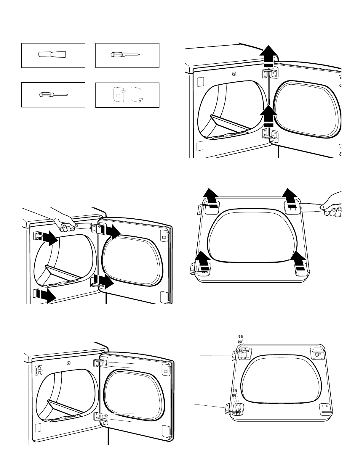
REVERSE DOOR SWING
Tools needed:
4. Remove the dryer door from the cabinet by lifting upward
and out. Lay the door on a towel or a soft cloth you placed
on a at workspace.
Plastic putty knife
Min. 8" long TORX T20
® †
screwdriver
#2 Phillips screwdriver
Optional Assembly Kit
Covers
You can change your door swing from a right-hinge opening
to a left-hinge opening, if desired.
Note:To complete the door swing reversal exactly as seen in
these instructions, a door reversal kit must be purchased. For
ordering information, please reference the “Use and Care Guide.”
1. Place a towel or soft cloth on a at workspace such as a oor
to avoid damaging the dryer’s surface or the dryer door.
Remove door from dryer cabinet
1. Open the dryer door.
2. Use a plastic putty knife to remove the hinge covers and
plastic covers from the front panel of the dryer. Set them aside.
5. Use a plastic putty knife to remove the door hinge covers.
Set them aside.
3. Using a T20® screwdriver, remove screws (A) and then
screws (B) from each of the 2 hinges attaching the dryer
door to the front panel of the dryer. Set the hinge screws off
to the side for use in reinstalling the door.
B
A
B
A
22
6. Using a #2 Phillips screwdriver, remove the remaining 4 screws
from the hinges. Then remove hinges A and B and set both the
screws and hinges aside.
A
B
†
® TORX and T20 are registered trademarks of Acument Intellectual Properties, LLC.
Page 23
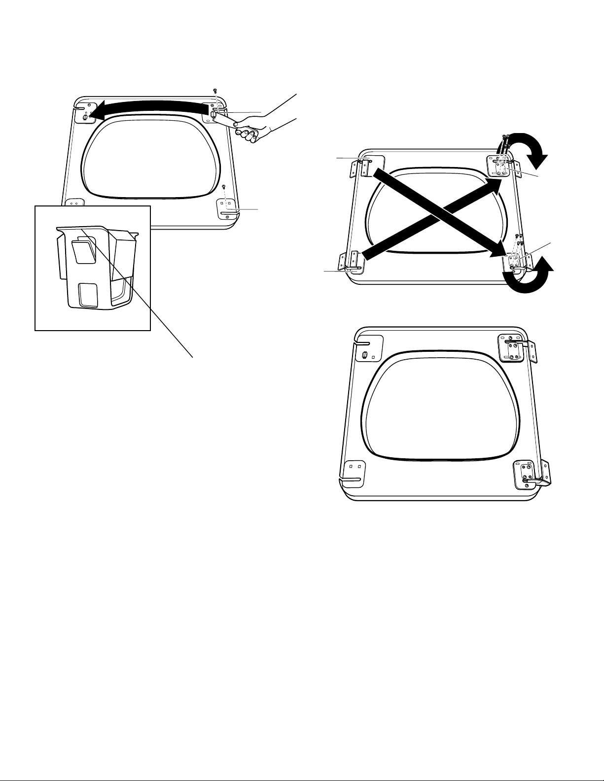
7. Using a #2 Phillips screwdriver, remove the screws from the
opposite side and set them aside. Then, using a plastic putty
knife, remove the door latch from the top of the door by
gently pushing in the metal tab and lifting. Repeat for
the top and remove the latch.
A
A
After removing the door latch,
move it to the opposite side,
place it in the open slot and
press it until the metal tabs
click into place. Replace the
screws you removed.
REINSTALL HINGES ON DOOR
1. Using the screws you set aside, reinstall hinge B (removed
from the lower-left corner of the door) in the upper-right
corner. Tighten all screws.
2. Using the screws you set aside, reinstall hinge A (removed
from the upper-left corner of the door) in the lower-right
corner. Tighten all screws.
A
B
A
B
Door Latch Detail
Metal Tab
23
Page 24
1
2
3
4
REVERSE DOOR STRIKE
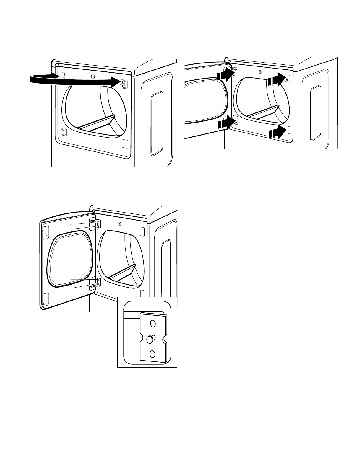
1. Using a T20
securing the door strike and move the door strike from the
left side of the dryer cabinet to the right side, securing it
with the removed screws.
2. Hang the door on the unit by placing set pin in dryer cabinet
hole and sliding door down. Using a Phillips screwdriver, install
screws 1 and 3 and then screws 2 and 4. Tighten all hinge
screws.
® †
screwdriver, remove the two screws
3. Install 2 plastic covers from the accessory kit into the spaces
where the hinges were removed. Place the plastic hinge
covers over the exposed hinges.
24
Set Pin
Page 25

NOTES
43
Page 26

W10757741C
W10820378C-SP
®/™ ©2016.
All rights reserved.
Tous droits réservés.
04/16
 Loading...