

Page 1
®
DRYER VENTING SPECIFICATIONS
Table of Contents
DRYER SAFETY............................................................................. 1
INSTALLATION REQUIREMENTS................................................ 3
Venting Requirements ................................................................. 4
DRYER INSPECTION AND CLEANING ....................................... 6
Frequency of Exhaust System Cleaning..................................... 6
Inspecting the Exhaust System................................................... 6
DRYER SAFETY
Your safety and the safety of others are very important.
We have provided many important safety messages in this manual and on your appliance. Always read and obey all safety
messages.
This is the safety alert symbol.
This symbol alerts you to potential hazards that can kill or hurt you and others.
All safety messages will follow the safety alert symbol and either the word “DANGER” or “WARNING.”
These words mean:
You can be killed or seriously injured if you don't immediately
DANGER
WARNING
All safety messages will tell you what the potential hazard is, tell you how to reduce the chance of injury, and tell you what can
happen if the instructions are not followed.
■ If you are installing a gas dryer, it is recommended that the owner post, in a prominent location, instructions for the customer’s use
in the event the customer smells gas. This information should be obtained from your local gas supplier.
■ Post the following warning in a prominent location.
FOR YOUR SAFETY
Do not store or use gasoline or other flammable vapors and liquids in the vicinity of this or any other appliance.
follow instructions.
can be killed or seriously injured if you don't
You
instructions.
follow
W10100920B
Page 2
WARNING: For your safety, the information in this manual must be followed to minimize
the risk of fire or explosion, or to prevent property damage, personal injury, or death.
– Do not store or use gasoline or other flammable vapors and liquids in the vicinity of this
or any other appliance.
– WHAT TO DO IF YOU SMELL GAS:
Do not try to light any appliance.
•
Do not touch any electrical switch; do not use any phone in your building.
•
Clear the room, building, or area of all occupants.
•
Immediately call your gas supplier from a neighbor's phone. Follow the gas supplier's
•
instructions.
If you cannot reach your gas supplier, call the fire department.
•
– Installation and service must be performed by a qualified installer, service agency, or
the gas supplier.
In the State of Massachusetts, the following installation instructions apply:
■ Installations and repairs must be performed by a qualified or licensed contractor, plumber, or gasfitter qualified or licensed by
the State of Massachusetts.
■ If using a ball valve, it shall be a T-handle type.
■ A flexible gas connector, when used, must not exceed 3 feet.
IMPORTANT SAFETY INSTRUCTIONS
WARNING:
including the following:
■
Read all instructions before using the dryer.
■
Do not place items exposed to cooking oils in your dryer.
Items contaminated with cooking oils may contribute to
a chemical reaction that could cause a load to catch fire.
■
Do not dry articles that have been previously cleaned in,
washed in, soaked in, or spotted with gasoline, drycleaning solvents, or other flammable or explosive
substances as they give off vapors that could ignite or
explode.
■
Do not allow children to play on or in the dryer. Close
supervision of children is necessary when the dryer is
used near children.
■
Before the dryer is removed from service or discarded,
remove the door to the drying compartment.
■
Do not reach into the dryer if the drum is moving.
■
Do not install or store the dryer where it will be exposed
to the weather.
■
Do not tamper with controls.
To reduce the risk of fire, electric shock, or injury to persons when using the dryer, follow basic precautions,
SAVE THESE INSTRUCTIONS
■
Do not repair or replace any part of the dryer or attempt
any servicing unless specifically recommended in this
Use and Care Guide or in published user-repair
instructions that you understand and have the skills to
carry out.
■
Do not use fabric softeners or products to eliminate static
unless recommended by the manufacturer of the fabric
softener or product.
■
Do not use heat to dry articles containing foam rubber or
similarly textured rubber-like materials.
■
Clean lint screen before or after each load.
■
Keep area around the exhaust opening and adjacent
surrounding areas free from the accumulation of lint, dust,
and dirt.
■
The interior of the dryer and exhaust vent should be
cleaned periodically by qualified service personnel.
■
See installation instructions for grounding requirements.
IMPORTANT: The gas installation must conform with local codes, or in the absence of local codes, with the National Fuel Gas
Code, ANSI Z223.1/NFPA 54.
The dryer must be electrically grounded in accordance with local codes, or in the absence of local codes, with the National
Electrical Code, ANSI/NFPA 70.
2
Page 3
INSTALLATION REQUIREMENTS
WARNING
Fire Hazard
Use a heavy metal vent.
Do not use a plastic vent.
Do not use a metal foil vent.
Failure to follow these instructions can result in death
or fire.
WARNING: To reduce the risk of fire, this dryer MUST BE
EXHAUSTED OUTDOORS.
NOTE: This guide is intended to aid qualified HVAC or
Architectural Engineers who design single and multi-dryer unit
venting systems for Whirlpool Corporation dryers sold in the
United States. Whirlpool Corporation provides required airflow
and back pressure specifications, measured at the connection
between the vent system and the dryer’s vent pipe, for use in the
design of dryer vent systems. Whirlpool does not design multidryer vent systems, nor does Whirlpool review or provide
approvals for vent systems designed by third-party engineering
firms.
Outside Exhaust
The four basic reasons for exhausting a dryer outdoors are
detailed in this section:
1. To meet codes requirements.
2. To remove moisture from laundry area.
3. To avoid lint accumulation in laundry area.
4. To remove excess heat from laundry area.
Codes Requirements
The following codes should be reviewed to ensure dryer vent
systems are in compliance:
1. International Mechanical Code: In the 2000 version, sections
504 and 913.
2. International Fuel Gas Code: In the 2003 version, section 614.
3. UL 2158 Electric Clothes Dryer Standard references venting
requirements in paragraph 7.3.
4. ANSI Z21.5.1 - Gas Clothes Dryers.
5. Other sections of these codes may also apply to multi-dryer
vent systems.
There are other codes requiring dryers to be exhausted when
installed in confined spaces where specified clearances from
combustible surfaces cannot be met. See the Installation
Instructions that came with your dryer for spacing requirements.
Local codes and ordinances that exist must also be met. Consult
your local building inspector for more information.
Improper venting can cause moisture and lint to collect
indoors, which may result in:
Moisture damage to woodwork, furniture, paint, wallpaper,
carpets, etc.
Housecleaning problems and health problems.
Moisture
A normal towel load contains some residual water when it is
removed from the washer. The dryer must remove this water and
discharge it from the drum. When the dryer is not exhausted
outside, this moist air will be recirculated through the heating
source, reducing the dryer’s efficiency.
Exhausting moisture into the room can also cause damage to
walls, floors and picture hangers and cause condensation on
windows and walls in cold weather.
Lint
Even though the dryer is equipped with a lint screen, fine
particles of lint can get through the screen and be exhausted out
of the dryer. Proper venting of the dryer will keep lint from
accumulating in the laundry area.
Heat
In order to remove moisture from the garments in the dryer, heat
is generated to vaporize the water. Exhausting the dryer outdoors
removes excess heat from the laundry area of the building.
Central Exhaust System Requirements
The following guidelines should be considered in the design of
any central exhaust system:
■ Exhaust individual dryers to the central exhaust duct system
with proper size vents to assure adequate performance of
each dryer. The dryer has 4" (10.2 cm) exhaust duct
connections. Four inch (10.2 cm) diameter aluminum vent
should be used to connect each dryer to the central vent.
■ Install weighted dampers on each individual dryer exhaust
duct. These dampers may be used for balancing out the
overall duct system.
■ Provide for a maximum of 0.1" (0.25 cm) of water column
vacuum in the central exhaust duct and a maximum of 0.6"
(1.5 cm) of water column back pressure at the connection of
each dryer exhaust vent at any time that the dryer is in
operation. See “Venting Requirements” for instructions on
how to measure water column back pressure.
■ Design the central duct system for sufficient capacity to
handle the maximum number of dryers operated at one time.
■ Consider moisture, lint and air temperature in the design of
the central duct system. Maximum exhaust temperature of
the dryer will not exceed 200°F (93.3°C) when the dryer is
operated according to the instructions provided with the
dryer.
■ Provide for periodic inspection and clean-out of lint
accumulated in the central duct system.
3
Page 4
Venting Requirements
Venting systems for Whirlpool dryers must meet the following
requirements:
■ The capacity to handle 200 CFM of air for each dryer in the
system.
■ A back pressure of 0.0" (0 cm) to 0.6" (1.5 cm) of water
column when measured at the connection to the dryer.
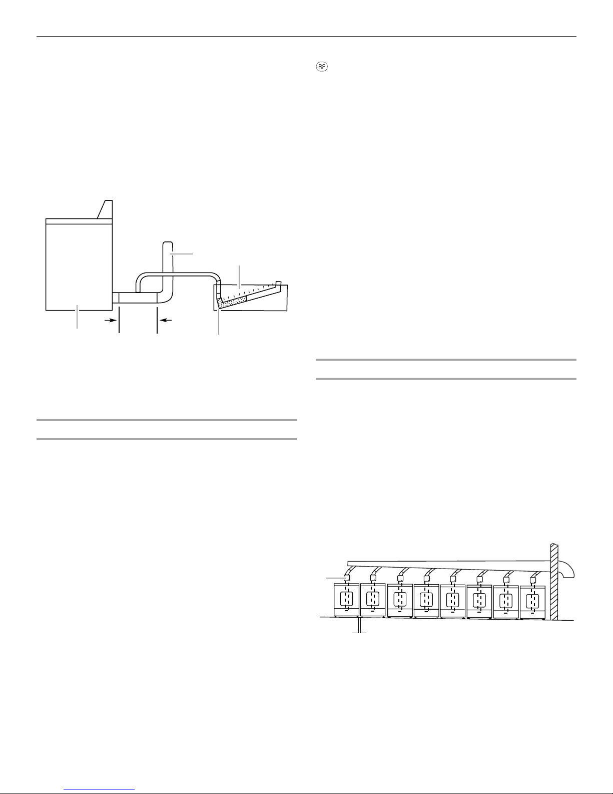
Back pressure should be measured with an empty dryer, a clean
lint screen and with the dryer operating in the Air Only cycle (no
heat). Use an inclined manometer, such as Dwyer model 102 (0"2" [0 cm - 5.1 cm] range) or Dwyer model 172 (0"-1" [0 cm -
2.5 cm] range) to measure the back pressure. See the following
illustration.
C
B
A
A. Dryer - empty and running on Air Only cycle
B. 12" (30.5 cm) min. of straight pipe - measure back
pressure from the center
C. To vent system
D. 0.6" (1.5 cm) water maximum back pressure
E. Inclined manometer
Single Dryer Venting Systems
Single dryer venting systems are defined as systems that have
only one dryer unit attached to a residential-type 4" (10.2 cm)
diameter rigid metal vent system. For single dryer venting
systems, see the Installation Instructions that came with your
dryer to determine the allowable length and number of elbows for
the venting system. In cases in which the Installation Instructions
do not address the vent length for the specific number of elbows
required for a particular application, the following calculations
may be used. (The total vent system length includes all straight
and curved portions of the vent system.):
■ For 90° elbows, reduce the allowable vent system length by
10 ft (3.05 m).
■ For 45° elbows, reduce the allowable vent system length by
6 ft (1.83 m).
For example, if the Installation Instructions state that a dryer is
allowed 40 ft (12.2 m) of total vent length with two 90° bends,
and the installation requires three 90° bends, the total allowable
vent length would be reduced by 10 ft (3.0 m) (from 40 ft [12.2 m]
to 30 ft [9.1 m]).
All Whirlpool electric dryer models, including “long vent dryers,”
that are sold in the United States and Canada are UL listed
(reference UL2158 standard), and all Whirlpool gas dryer models
are CSA listed (reference ANSI Z21.5.1 standard). These
standards require testing at the maximum-rated exhaust vent
conditions that are published in the product literature for each
individual model. The designation for the UL or CSA listing can
be found on or adjacent to the serial label on the product.
D
E
“AF” Code
Certain electronic dryer models have airflow detection
capabilities. (See specific model product literature for details). If
the airflow in the dryer is extremely low, an “AF” code will be
displayed on the control panel. For single dryer venting systems,
this code means that you may have a blocked or partially blocked
vent or that your overall vent system length is too long. To resolve
this issue:
■ Check to see if the vent run from the dryer to the wall is
crushed. Refer to the “Venting Requirements” section of
the Use and Care Guide for more information.
■ Confirm that the vent run from the dryer to the wall is free
of lint and debris.
■ Confirm that the exterior vent exhaust hood is free of lint
and debris.
■ Confirm that your vent system falls within the
recommended run length and number of elbows for the
type of vent you are using. Refer to the “Plan Vent
System” section of the Use and Care Guide for details.
■ Select a Timed Dry heated cycle, and restart the dryer.
■ If the message persists, have your entire home venting
run cleaned.
For multi-dryer venting systems, the “AF” code means that your
vent may be blocked or partially blocked or that the venting
system is creating back pressure in excess of the maximum
allowable 0.6” (1.5 cm) water column. In this case, the
engineering firm that designed the system should be consulted.
Multiple Dryer Venting Systems
Multiple dryer venting systems must be designed specifically for
each application.
NOTE: It is recommended that an architectural or HVAC
engineering firm be consulted for designing the dryer venting
system.
Connecting a number of dryers to a single vent system is
common in coin-laundry stores and in many apartment buildings.
Listed here are some requirements for examples of three different
multiple dryer venting systems.
Option 1 - Horizontal System
The most common is the horizontal system, in which banks of
dryers are all located in one room and vented through a common
duct. See the following illustration for an example of a generic
horizontal system.
A
1"*
(2.5 cm)
A. 4" (10.2 cm) diameter rigid metal back draft damper
*Minimum spacing required between dryers
4
Page 5
Option 2 - Vertical System
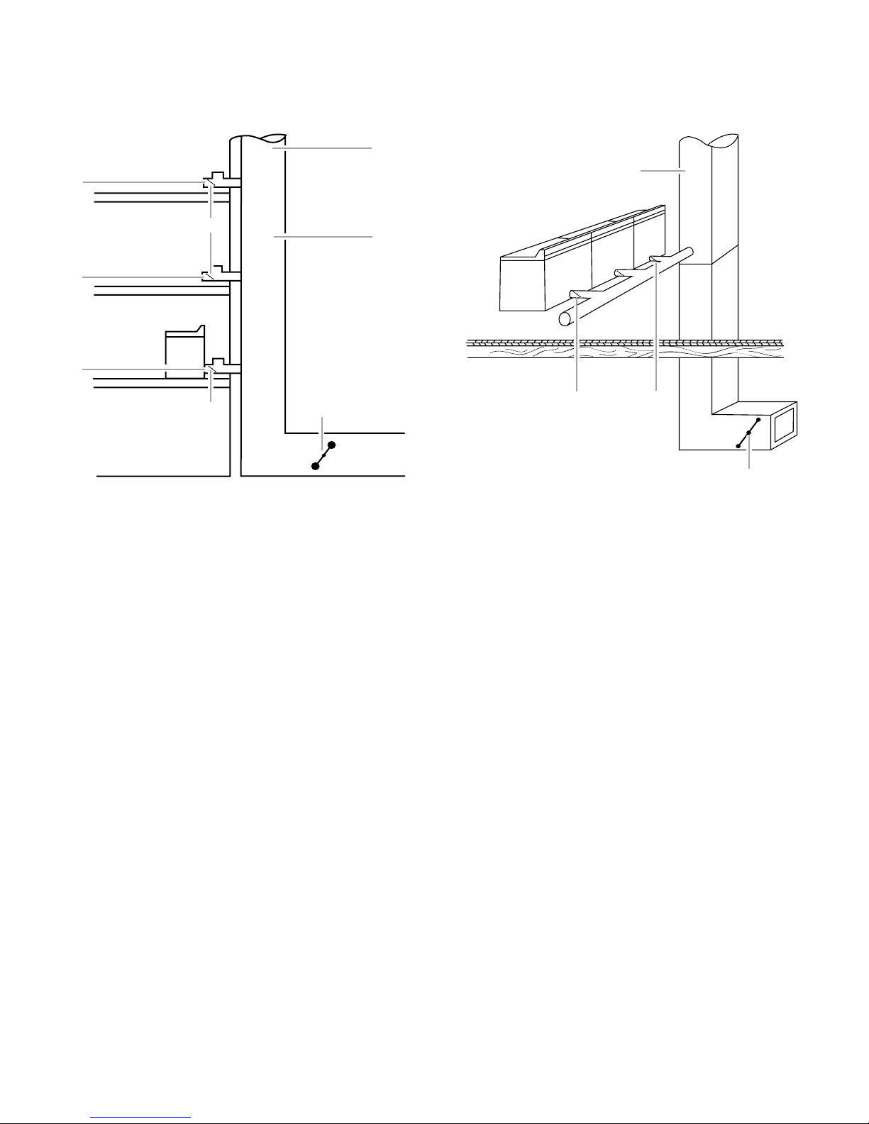
The vertical system is used in some apartment buildings that
have a washer and dryer on each floor. Each dryer is exhausted
into the same central vertical duct. See the following illustration
for an example of a generic vertical system.
D
A
Option 3 - Combination System
The combination system may be used in high-rise apartments,
with a bank of dryers installed at several different levels. Each of
these banks then exhausts into a central vertical vent. See the
following illustration for an example of a combination system.
A
F
E
B
C
F
F
BC
E
G
D
A. 0.6" (1.5 cm) water column maximum back pressure
B. Weighted dampers
C. Individual dryer exhaust - on each floor
D. 0.1" (0.25 cm) water column maximum vacuum
E. Main duct
F. Barometric damper (use depends on exhaust
system design)
G. Source of outside air
A. Central vertical duct - maximum of 0.1"
(0.25 cm) water column vacuum
B. Weighted damper (each dryer)
C. Maximum of 0.6" (1.5 cm) water column
back pressure
D. Barometric damper (use depends on
exhaust system design)
E. Outside air source
5
Page 6

DRYER INSPECTION AND CLEANING
Frequency of Exhaust System Cleaning
Every exhaust system must be inspected periodically and
cleaned to ensure that it is intact and free from lint accumulation.
The frequency of these inspections will vary, depending on the
system and usage of the dryer. For single-family usage, an annual
inspection is recommended. In commercial usage or in multiple
dryer systems a more frequent inspection is recommended.
Complaints of long drying times or a hot dryer top indicate the
need for inspection of the exhaust system.
Inspecting the Exhaust System
1. Disconnect the exhaust duct from the dryer and from the
exhaust hood (at the exhaust outlet).
2. Inspect the interior of the duct and remove any lint
accumulation.
■ Be sure that lint is removed from the exhaust hood. Lint
may collect in the exhaust hood so that the flappers or
louvers (if installed as part of the exhaust system) will not
open or close completely.
■ After cleaning the exhaust hood, check that the flapper or
louvers move freely.
3. Reassemble the exhaust duct and hood, checking that the
joints are secure.
4. Operate the dryer and verify that the exhaust air is not
obstructed in the vent and that there are no leaks in the
system.
■ Seal any leaks found.
W10100920B
© 2007. Whirlpool Corporation.
All rights reserved.
Printed in U.S.A.
7/07
 Loading...