

Whirlpool WAHU, WAHM Installation Instructions Manual
AIR HANDLER INSTALLATION INSTRUCTIONS
Table of Contents
AIR HANDLER SAFETY .................................................................1
INSTALLATION REQUIREMENTS................................................2
Tools and Parts ............................................................................2
Outdoor System Requirements ...................................................2
Location Requirements................................................................ 2
Installation Configurations ...........................................................3
Drain Pan Connections ................................................................4
Electrical Requirements—Models Without
Factory-Installed Electric Heat.....................................................5
Electrical Requirements—Models With
Factory-Installed Electric Heat.....................................................5
Ductwork Requirements ..............................................................6
INSTALLATION INSTRUCTIONS..................................................6
Inspect Shipment.........................................................................6
AIR HANDLER SAFETY
Your safety and the safety of others are very important.
We have provided many important safety messages in this manual and on your appliance. Always read and obey all safety
messages.
Install Condensate Drain..............................................................7
Install Ductwork............................................................................7
Verify Orifice Size .........................................................................8
Connect Refrigerant Lines ...........................................................8
Make Electrical Connections—Models Without
Factory-Installed Electric Heat.....................................................8
Make Electrical Connections—Models With
Factory-Installed Electric Heat.....................................................9
Complete Installation..................................................................12
SEQUENCE OF OPERATION ......................................................14
AIR HANDLER MAINTENANCE ..................................................14
ASSISTANCE OR SERVICE.........................................................14
Accessories ................................................................................14
WARRANTY ..................................................................................15
This is the safety alert symbol.
This symbol alerts you to potential hazards that can kill or hurt you and others.
All safety messages will follow the safety alert symbol and either the word “DANGER” or “WARNING.”
These words mean:
You can be killed or seriously injured if you don't immediately
DANGER
WARNING
All safety messages will tell you what the potential hazard is, tell you how to reduce the chance of injury, and tell you what can
happen if the instructions are not followed.
Whirlpool® Models WAHU, WAHM
065937400
follow instructions.
can be killed or seriously injured if you don't
You
instructions.
follow
INSTALLATION REQUIREMENTS
These instructions are intended as a general guide only and do
not supersede any national or local codes in any way.
Compliance with all local, state, or national codes pertaining to
this type of equipment should be determined prior to installation.
Read this entire instruction manual, as well as the instructions
supplied in separate equipment, before starting the installation.
All models are designed for indoor installation only.
The installation of the air handler, field wiring, warm air ducts, etc.
must conform to the requirements of the National Electrical
Code, ANSI/NFPA No. 70 (latest edition) in the United States, and
any state laws, and local ordinances (including plumbing or
wastewater codes). Local authorities having jurisdiction should
be consulted before installation is made. Such applicable
regulations or requirements take precedence over the general
instructions in this manual.
Install the conditioned air plenum, ducts and air filters (not
provided) in accordance with NFPA 90B Standard for the
Installation of Warm Air Heating and Air-Conditioning Systems
(latest edition).
The air handler is provided with flanges for the connection of the
plenum and ducts.
Air filters must be listed as Class 2 furnace air filters.
The air handler is shipped from the factory completely
assembled. Some models are configured for upflow air discharge
only, and some models are configured for upflow or horizontal
left-hand air discharge.
Do not remove the cabinet knockouts until it has been
determined which knockouts will need to be removed for the
installation.
Select the final installation position which best suits the site
conditions. Consider required clearances, space, routing
requirements for refrigerant line, condensate disposal, filters,
ductwork, wiring, and accessibility for service. Refer to the air
handler rating plate on the air handler for specific information.
Tools and Parts
Gather the required tools and parts before starting installation.
Read and follow the instructions provided with any tools listed
here.
Tools Needed
■ ¹⁄₄" nut driver
■ Level
■ Screwdriver
■ Adjustable wrench
Parts Needed
Check local codes, check existing electrical supply, and read
“Ductwork Requirements,” and “Electrical Requirements,” before
purchasing parts.
■ UL listed wire nuts
■ Replacement orifice (if needed). See “Verify Orifice Size.”
The correct orifice size may be contained in the
replacement orifice package located inside the control box
of the outdoor unit. If this package does not contain the
correct orifice for your air handler, you must purchase the
correct orifice size.
■ Tape measure
■ Hammer
■ Sealant
Outdoor System Requirements
The air handler is designed to match, and must be used with,
outdoor units as rated. The indoor sections are manufactured
with an interchangeable refrigerant metering orifice to provide
optimum refrigerant control and system performance with a
variety of different capacities of outdoor units.
In some cases, the rating of the outdoor unit may require that the
air handler coil assembly orifice be changed to obtain rated
performance.
Location Requirements
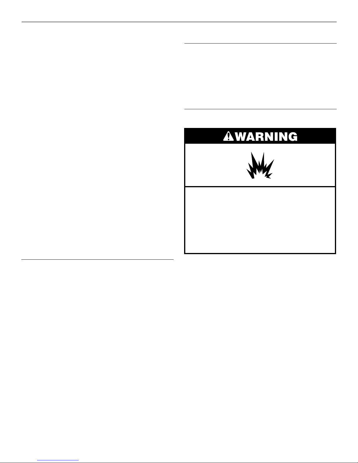
Explosion Hazard
Keep flammable materials and vapors, such as
gasoline, away from air handler.
Place air handler so that heating elements are at least
18 inches (46 cm) above the floor for a garage
installation.
Failure to follow these instructions can result in death,
explosion, or fire.
NOTE: When used on cooling applications, excessive sweating
may occur when the air handler is installed in a very humid
space.
■ If installed in an unconditioned space, sealant should be
applied around the electrical wires, refrigerant tubing, and
condensate lines where they enter the cabinet.
■ Electrical wires should be sealed on the inside where they exit
the conduit opening. Sealant is required to prevent air
leakage into and condensate from forming inside the air
handler, control box, and on electrical controls.
■ The air handler must be installed in such a way as to allow
free access to the coil/filter compartment and blower/control
compartment.
■ When installed in the horizontal position, the air handler must
have a ³⁄₄" drop toward the drain outlet of the drain pan to
ensure proper condensate drainage.
2
Installation Clearances
Non-Ducted Return Closet Installation
The air handler can be installed in a closet with a false bottom to
form a return air plenum or be installed with a return air plenum
under the air handler.
Louvers or return air grilles are field supplied. Local codes may
limit application of systems without a ducted return to singlestory buildings.
■ For a unit installed in a closet with a louvered return opening,
the minimum open area for the louvers will be as shown
below.
18" and 24" models 320 sq. in.
30" and 36" models 360 sq. in.
42", 48" and 60" models 450 sq. in.
■ If the free area is not known, assume a 25% free area for
wood or a 75% free area for metal louvers or grilles.
■ Using the louver dimensions and the 25% or 75%
assumption, determine if the louver open area meets the
minimum open area listed above.
■ If the return air plenum is used, the return air grille should be
immediately in front of the opening in the plenum to allow for
the free flow of return air.
■ When not installed in front of the opening, there must be
adequate clearance around the air handler to allow for the
free flow of return air.
Conversion from Vertical to Horizontal
An upflow only air handler may be converted to horizontal air
discharge by installing a horizontal drain pan kit. See
“Accessories.”
An upflow/horizontal air handler may be converted from
horizontal left-hand discharge to horizontal right-hand discharge
without additional parts.
Suspended Cabinet Installation
NOTE: Air handlers cannot be installed horizontally lying on or
suspended from either the front or back of the air handler. It must
be positioned with one side parallel to the floor when in the
horizontal position.
The suspending means must be field fabricated, and should
consist of 2 “cradles” made by attaching 2 rods to a length of
angle iron or suitable gauge steel.
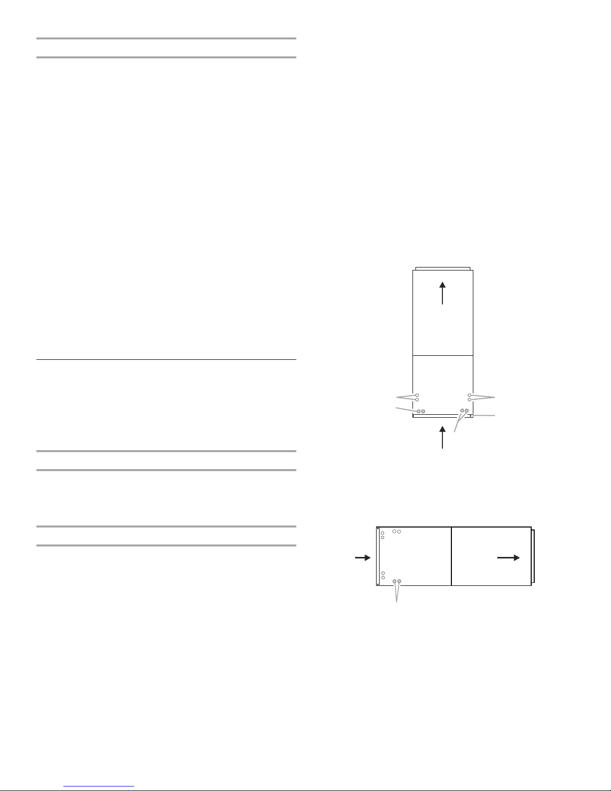
Installation Configuration Options
Shading indicates proper line connections
As shipped from the factory
Upflow
(return in bottom)
Installation Configurations
For ease in installation, it is best to make any necessary coil
configuration changes before setting air handler in place. See
“Installation Configuration Options.”
■ Upflow air discharge only contains 1 drain pan.
■ Upflow or horizontal airflow contains 2 drain pans.
Vertical Installations
Upflow
The air handler must be supported on the bottom only and set on
a field-supplied supporting frame with an air return opening.
Securely attach the air handler to the supporting frame.
Horizontal Installations
Horizontal installations can be left-hand or right-hand air supply.
Adequate support must be provided to ensure cabinet integrity.
Ensure that there is adequate room to remove, service and
access panels if installing in the horizontal position. For correct
horizontal coil installation, see “Installation Configuration
Options” later in this section.
IMPORTANT:
■ This coil is provided with a secondary drain that should be
trapped and piped to a location that will give the occupant a
visual warning that the primary drain is clogged. See “Install
Condensate Drain.”
■ When an evaporator coil is installed in an attic or above a
finished ceiling, an auxiliary drain pan should be provided
under the air handler as specified by most local building
codes.
A
B
A. Horizontal drain connections
(left or right hand)
Horizontal Right
Left to Right Airflow: Requires drain pan
Drains
location change.
A
A. Drain connections
A
C
B
B. Upflow drain connections
C. Bottom/filter frame
3
Horizontal Left
F
.
Factory ready (on some models)
Conversion to Horizontal Right
Before Conversion
D
Drains
BC
A. Drain connections
B. Coil access cover
C. Blower access cover
A
Drain Pan Connections
Horizontal Installations can be either “Right” or “Left.”
For Horizontal Right Installations, a drain pan location change is
required. Use drain connections marked “A” below.
Left to Right Airflow: Requires drain pan
Drains
For Horizontal Left Installations, use drain connections marked
“A” below.
Horizontal Right
location change.
A
A. Drain connections
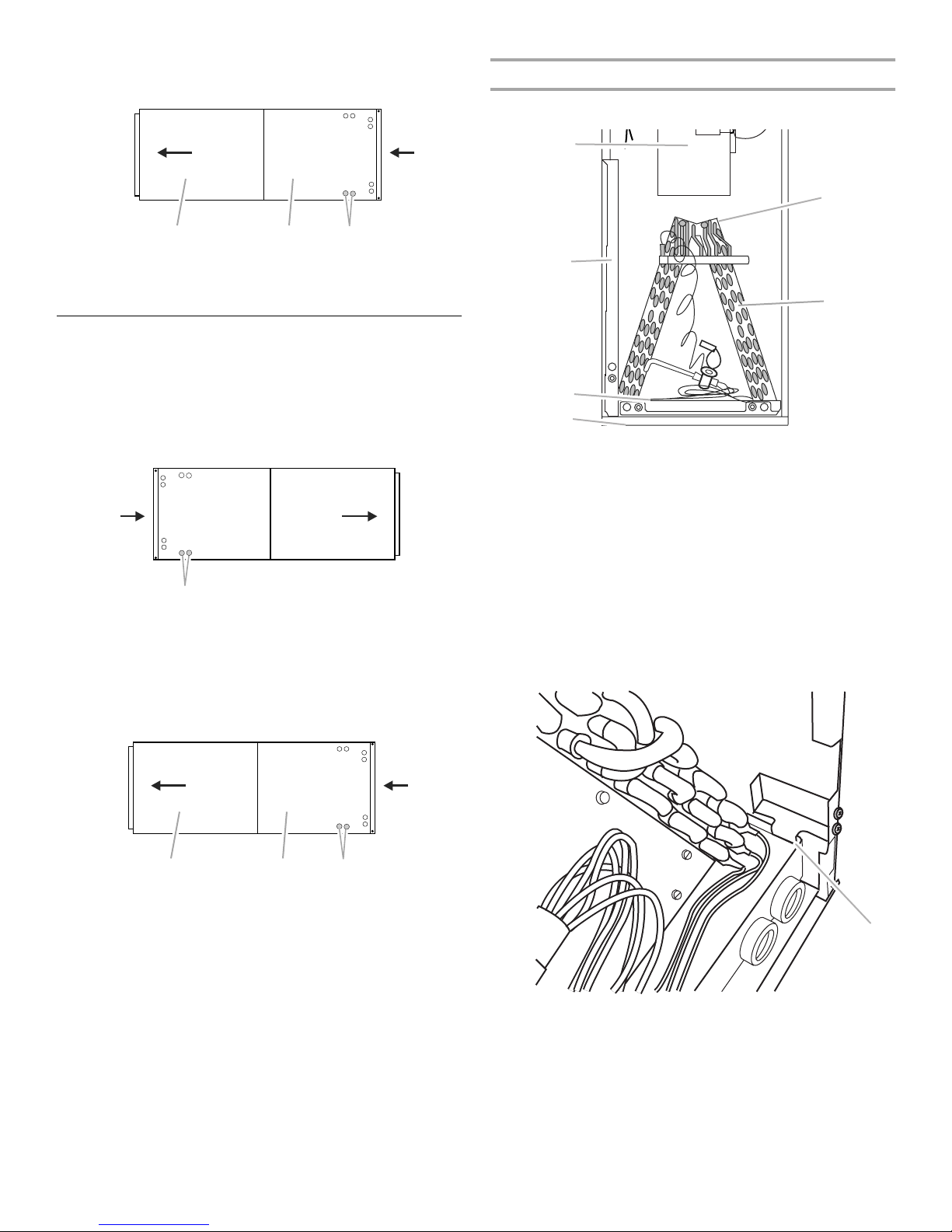
E
C
B
A
A. Filter access door
B. Bottom drain pan
C. Side drain pan
D. Blower
E. Top cap
F. Coil/Drain pan assembly
(consists of coil, bottom
drain pan and side drain pan)
1. Remove screws from the blower access cover and lift off of
the unit. Set aside.
2. Remove screws from the coil access cover and lift off of the
unit. Set aside.
3. Remove screws from the coil support bracket and lift off of
the unit. Set aside.
4. Remove the coil/drain pan assembly by lifting and sliding out.
The assembly consists of the coil, the bottom drain pan and
the side drain pan.
Horizontal Left
Factory ready (on some models)
BC
A. Drain connections
B. Coil access cover
C. Blower access cover
Drains
A
A
A. Coil support bracket
5. Remove the side drain pan from the coil/drain pan assembly
and install on the opposite side.
6. Reinstall the coil/drain pan assembly in the same orientation
as before by lifting and sliding into the air handler.
7. Install the coil support bracket on the opposite side of the air
handler.
4
After Conversion
F
■ The power supply must be sized and protected according to
E
D
the specifications supplied on the product.
■ This air handler is factory-configured for 120-volt or 240-volt,
single phase, 60 cycles. For 208-volt applications, see
“208-Volt Conversion” in the “Make Electrical Connections—
Models Without Factory-Installed Electric Heat” section.
■ For optional electric heater applications, see “Accessories.”
Refer to the instructions provided with the accessory for
proper installation.
Electrical Requirements—Models With
Factory-Installed Electric Heat
C
A
B
A. Coil support bracket
B. Filter access door
C. Bottom drain pan
8. Determine knockouts required for drain line connections and
remove.
9. Replace the blower and coil access covers.
D. Side drain pan
E. Blower
F. To p c ap
Electrical Requirements—Models Without
Factory-Installed Electric Heat
WARNING
Electrical Shock Hazard
Electrically ground air handler.
Connect ground wire to ground terminal marked “GND”.
Failure to do so can result in death or electrical shock.
NOTE: Use copper conductors only.
■ All field wiring must be done in accordance with National
Electrical Code, applicable requirements of UL and local
codes, where applicable.
■ Electrical wiring, disconnect means and over-current
protection are to be supplied by the installer. Refer to the air
handler rating plate for maximum over-current protection,
minimum circuit ampacity, as well as operating voltage.
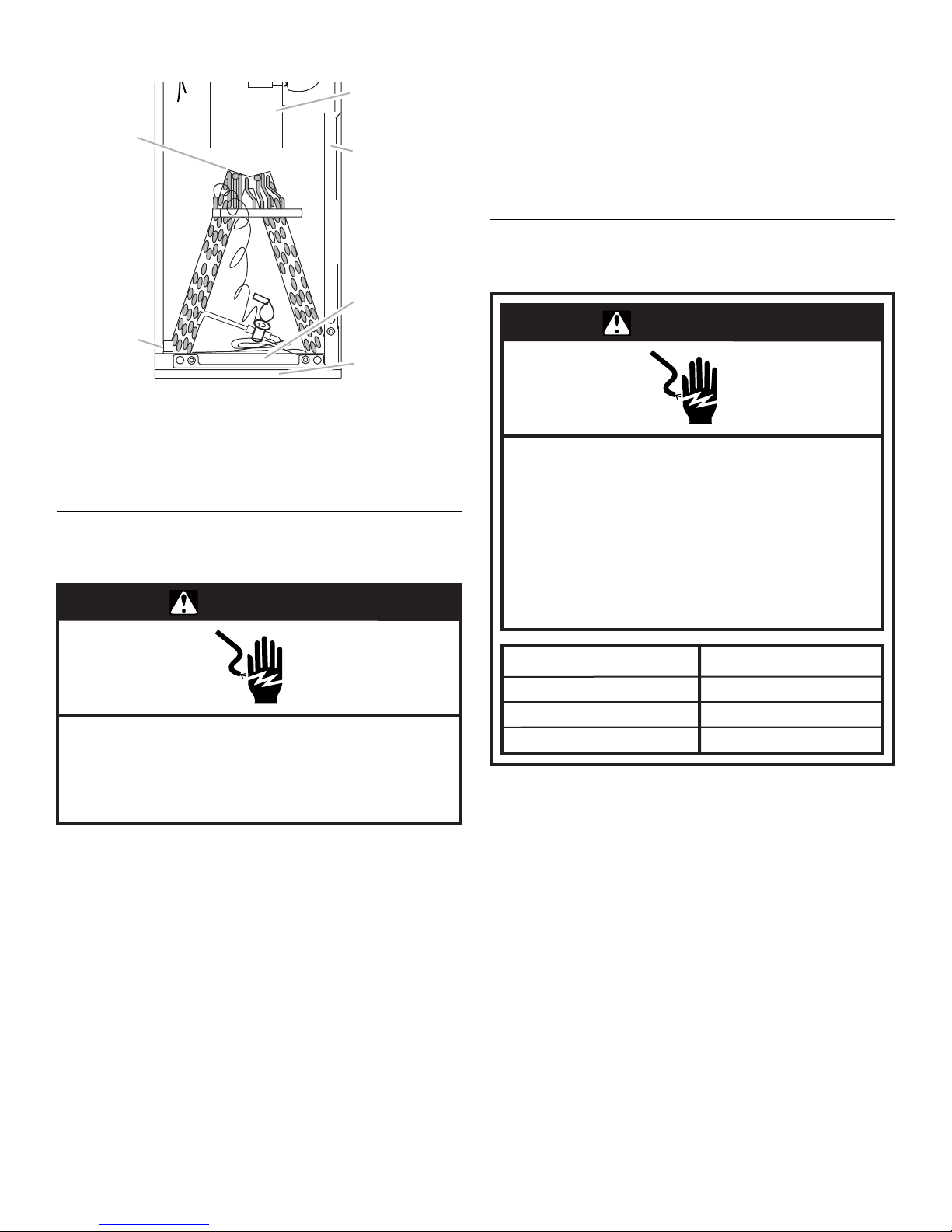
WARNING
Electrical Shock Hazard
Electrically ground electric heater.
Connect ground wire to ground terminal
marked “GND.”
Use copper wire rated for supply connection.
Correct wire gauge is shown in the chart below.
Failure to follow these instructions can result in
death or electrical shock.
Rating Plate Ampacity
21 - 30
31 - 40
41 - 60
NOTE: Use copper conductors only.
■ All field wiring must be done in accordance with National
Electrical Code, applicable requirements of UL and local
codes, where applicable.
■ Electrical wiring, disconnect means and over-current
protection are to be supplied by the installer. Refer to the air
handler rating plate for maximum over-current protection,
minimum circuit ampacity, as well as operating voltage.
■ The power supply must be sized and protected according to
the specifications supplied on the product.
■ This air handler is factory-configured for 240-volt, single
phase, 60 cycles. For 208-volt applications, see “208-Volt
Conversion” in the “Make Electrical Connections—Models
Without Factory-Installed Electric Heat” section.
AWG
10
8
6
5
 Loading...