

Whirlpool WAHMS, WAHME Installation Instructions And Owner's Manual
AIR HANDLER INSTALLATION INSTRUCTIONS
Table of Contents
AIR HANDLER SAFETY................................................................. 1
INSTALLATION REQUIREMENTS................................................ 2
Tools and Parts............................................................................ 3
System Requirements ................................................................. 3
Location Requirements................................................................ 3
Electrical Requirements............................................................... 4
Ductwork Requirements.............................................................. 4
INSTALLATION INSTRUCTIONS.................................................. 4
Inspect Shipment......................................................................... 4
Installation Configurations ........................................................... 5
Install Condensate Drain.............................................................. 7
AIR HANDLER SAFETY
Install Ductwork ........................................................................... 8
Verify Orifice Size......................................................................... 8
Connect Refrigerant Lines........................................................... 8
Make Electrical Connections....................................................... 9
Complete Installation................................................................. 17
SEQUENCE OF OPERATION...................................................... 19
Cooling—Cooling Only or Heat Pump ...................................... 19
Heating—Electric Heat Only...................................................... 19
Heating—Heat Pump................................................................. 19
AIR HANDLER MAINTENANCE.................................................. 19
ASSISTANCE OR SERVICE ........................................................ 20
Accessories................................................................................ 20
Recognize this symbol as a safety precaution.
Recognize Safety Symbols, Words and Labels
The following symbols and labels are used throughout this
manual to indicate immediate or potential hazards. It is the
owner’s responsibility to read and comply with all safety
information and instructions accompanying these symbols.
Failure to heed safety information increases the risk of serious
personal injury or death, property damage and/or product
damage.
WARNING
Hazards or unsafe practices could result in property
damage, product damage, severe personal injury or death.
Goodman 1
CAUTION
Hazards or unsafe practices may result in property
damage, product damage, personal injury or death.
CAUTION
Hazards or unsafe practices may result in property
or product damage.
Goodman 9
WARNING
Installation and repair of this unit should
be performed ONLY by individuals meeting
the requirements of an “Entry Level Technician”
as specified by the Air-Conditioning, Heating and
Refrigeration Institute (AHRI). Attempting to
install or repair this unit without such background may
result in product damage, personal injury or death.
Goodman 7
WARNING
HIGH VOLTAGE!
Disconnect ALL power before servicing.
Multiple power sources may be present.
Failure to do so may cause property damage,
personal injury or death.
Goodman 6
Whirlpool® Models WAHMS, WAHME
WPIO-355B
WARNING
This product is factory-shipped for use with 208/240/1/60
electrical power supply. DO NOT reconfigure this air
handler to operate with any other power supply.
Goodman 33
WARNING
To avoid property damage, personal injury or death due to
electrical shock, this unit MUST have an uninterrupted,
unbroken electrical ground. The electrical ground circuit
may consist of an appropriately sized electrical wire
connecting the ground lug in the unit control box to the
building electrical service panel.
Other methods of grounding are permitted if performed
in accordance with the National Electric Code (NEC)
/American National Standards Institute (ANSI) /National
Fire Protection Association (NFPA) 70 and local/state
codes. In Canada, electrical grounding is to be in
accordance with the Canadian Electric Code (CSA) C22.1.
Goodman 34
CAUTION
When installing or servicing this equipment, safety
clothing, including hand and eye protection, is strongly
recommended. If installing in an area that has special
safety requirements (hard hats, etc.), observe these
requirements.
Goodman 35
WARNING
Do not connect to or use any device that is not designcertified for use with this unit. Serious property damage,
personal injury, reduced unit performance and/or hazardous
conditions may result from the use of such non-approved
devices.
Goodman 36
DANGER
CARBON MONOXIDE POISONING HAZARD
Special Warning for Installation of Furnace or Air Handling
Units in Enclosed Areas such as Garages, Utility Rooms or
Parking Areas.
Carbon monoxide producing devices (such as an
automobile, space heater, gas water heater, etc.) should
not be operated in enclosed areas such as unventilated
garages, utility rooms or parking areas because of the
danger of carbon monoxide (CO) poisoning resulting from
the exhaust emissions. If a furnace or air handler is
installed in an enclosed area such as a garage, utility room
or parking area and a carbon monoxide producing device is
operated therein, there must be adequate, direct outside
ventilation.
This ventilation is necessary to avoid the danger of CO
poisoning which can occur if a carbon monoxide producing
device continues to operate in the enclosed area. Carbon
monoxide emissions can be (re)circulated throughout the
structure if the furnace or air handler is operating in any
mode.
CO can cause serious illness including permanent brain
damage or death.
Goodman 38
Goodman 37
WARNING
To prevent the risk of property damage, personal injury, or
death, do not store combustible materials or use gasoline
or other flammable liquids or vapors in the vicinity of this
unit.
INSTALLATION REQUIREMENTS
These instructions are intended as a general guide only for use by
qualified persons and do not supersede any national or local
codes in any way. Compliance with all local, state, or national
codes pertaining to this type of equipment should be determined
prior to installation.
Read this entire instruction manual, as well as the instructions
supplied in separate equipment, before starting the installation.
All models are designed for indoor installation only.
The installation of the air handler, field wiring, warm air ducts, etc.
must conform to the requirements of the National Electrical
Code, ANSI/NFPA No. 70 (latest edition) in the United States, and
any state laws, and local ordinances (including plumbing or
wastewater codes). Local authorities having jurisdiction should
be consulted before installation is made. Such applicable
regulations or requirements take precedence over the general
instructions in this manual.
IMPORTANT: The United States Environmental Protection
Agency (EPA) has issued various regulations regarding the
introduction and disposal of refrigerants in this unit. Failure to
follow these regulations may harm the environment and can lead
to the imposition of substantial fines. These regulations may vary
by jurisdiction. A certified technician must perform the installation
and service of this product. Should questions arise, contact your
local EPA office.
This product is designed and manufactured to permit installation
in accordance with national codes. It is the installer’s
responsibility to install this unit in accordance with national codes
and/or prevailing local codes and regulations.
Install the conditioned air plenum, ducts and air filters (not
provided) in accordance with NFPA 90B Standard for the
Installation of Warm Air Heating and Air-Conditioning Systems
(latest edition).
The air handler is provided with flanges for the connection of the
plenum and ducts.
Air filters (not provided) must be listed as Class 2 furnace air
filters.
The air handler can be used with R-410A from the factory.
The air handler is shipped from the factory completely
assembled. Some models are configured for upflow air discharge
only, and some models are configured for upflow or horizontal
left-hand air discharge. The air handler cabinet conforms to
2 percent or less air leakage.
2

Do not remove the cabinet knockouts until it has been
determined which knockouts will need to be removed for the
installation.
Select the final installation position which best suits the site
conditions. Consider required clearances, space, routing
requirements for refrigerant line, condensate disposal, filters,
ductwork, wiring, and accessibility for service. Refer to the air
handler rating plate on the air handler for specific information.
Tools and Parts
Gather the required tools and parts before starting installation.
Read and follow the instructions provided with any tools listed
here.
Tools Needed
■ ¹⁄₄" nut driver
■ Level
■ Screwdriver
■ Adjustable wrench
■ Tape measure
■ Hammer
■ Sealant
Parts Needed
Check local codes, check existing electrical supply, and read
“Ductwork Requirements” and “Electrical Requirements” before
purchasing parts.
■ UL-Listed wire connectors
■ Replacement orifice (if needed). See “Verify Orifice Size.” The
correct orifice size may be contained in the replacement
orifice package located inside the control box of the outdoor
unit. If this package does not contain the correct orifice for
your air handler, you must purchase the correct orifice size.
System Requirements
The air handler is designed to match, and must be used with
outdoor units as rated. The indoor units are manufactured with an
interchangeable refrigerant metering orifice to provide optimum
refrigerant control and system performance with a variety of
different capacities of outdoor units.
In some cases, the rating of the outdoor unit may require that the
air handler coil assembly orifice be changed to obtain rated
performance.
Location Requirements
NOTE: When used on cooling applications, excessive sweating
may occur when the air handler is installed in a very humid
space.
■ If the air handler is installed in an unconditioned space,
sealant should be applied around the electrical wires,
refrigerant tubing, and condensate lines where they enter the
cabinet.
■ Electrical wires should be sealed on the inside where they exit
the conduit opening. Sealant is required to avoid air leakage
and condensate from forming inside the air handler, control
box, and on the electrical controls.
■ The air handler must be installed in such a way as to allow
free access to the coil/filter compartment and blower/control
compartment.
■ The air handler must be installed in a level position to ensure
proper condensate drainage.
Installation Clearances
Non-Duct Return Closet Installation
The air handler can be installed in a closet with a false bottom to
form a return air plenum or be installed with a return air plenum
under the air handler.
Louvers or return air grilles are field supplied. Local codes may
limit the application of systems without a duct return to singlestory buildings.
■ For an air handler installed in a closet with a louvered return
opening, the minimum open area for the louvers will be as
shown below.
2
18" and 24" (45.7 cm and
320 sq. in. (2,065 cm
61 cm) models
30" and 36" (76.2 cm and
360 sq. in. (2,323 cm
91.4 cm) models
42", 48" and 60" (106.7 cm,
450 sq. in. (2,903 cm
121.9 cm and 152.4 cm) models
■ If the free area is not known, assume a 25% free area for
wood louvers or a 75% free area for metal louvers or grilles.
■ Using the louver dimensions and the 25% or 75%
assumption, determine if the louver open area meets the
minimum open area listed in the previous chart.
■ If the return air plenum is used, the return air grille should be
immediately in front of the opening in the plenum to allow for
the free flow of return air.
■ When the air handler is not installed in front of the opening,
there must be adequate clearance around the air handler to
allow for the free flow of return air.
■ The unit clearance from a combustible surface may be 0".
■ Allow a minimum of 24" (61 cm) in front of the unit for service
clearance.
■ Do not install the air handler in a location that violates the
instructions provided with the condenser.
■ If the unit is located in an area with high ambient temperature
and/or high humidity, the air handler may have condensation
on the casing. On these installations, a wrap of 2" (5.1 cm)
fiberglass insulation with a vapor barrier is recommended.
■ Consult all appropriate regulatory codes prior to determining
final clearances.
■ When installing this unit in an area that may become wet,
elevate the unit with a sturdy, non-porous material.
■ In installations that may lead to physical damage (for
example. in a garage) it is recommended that a barrier be
installed to avoid such damage.
)
2
)
2
)
3
Electrical Requirements
WARNING
To avoid the risk of injury, electrical shock or death, the
furnace must be electrically grounded in accordance with
local codes or, in their absence, with the latest edition of the
National Electric Code (NEC).
NOTES:
■ Use copper conductors only.
■ All field wiring must be done in accordance with National
Electrical Code, applicable requirements of UL and local
codes where applicable.
■ Electrical wiring, disconnect means and overcurrent
protection are to be supplied by the installer. Refer to the air
handler rating plate for maximum overcurrent protection,
minimum circuit ampacity, as well as operating voltage.
■ The power supply must be sized and protected according to
the specifications supplied on the product.
■ This air handler is factory-configured for 240-volt, single
phase, 60 cycles. For 208-volt applications, see “208-Volt
Conversion” in the “Make Electrical Connections” section.
■ For optional electric heater applications, see “Accessories.”
Refer to the instructions provided with the accessory for
proper installation.
Goodman 31
Ductwork Requirements
■ Install the conditioned air plenum, ducts and air filters (not
provided) in accordance with NFPA 90B Standard for the
Installation of Warm Air Heating and Air-Conditioning
Systems (latest edition).
■ The air handler is provided with flanges for the connection of
the plenum and ducts.
■ The air handler is equipped with flanges that can form a filter
rack for the installation of the air filter, or the filter may be
installed as part of the return air duct system.
■ Air filters must be listed as Class 2 furnace air filters.
CAUTION
Do not operate this product without all the ductwork
attached.
■ Supply and return ductwork must be adequately sized to
■ Supply plenum should be the same size as the flanged
Goodman 39
meet the system’s air requirements and static pressure
capabilities. To ensure correct system performance, the
ductwork is to be sized to accommodate 375 to 425 CFM per
ton of cooling with the static pressure not to exceed 0.5"
W.C. Ductwork should be insulated with a minimum of 1"
(2.5 cm) thick insulation with a vapor barrier in conditioned
areas or 2" (5.1 cm) minimum in unconditioned areas.
opening provided around the blower outlet and should
extend ideally at least 36" (91.4 cm) from the air handler
before turning or branching off plenum into duct runs. The
plenum forms an extension of the blower housing and
minimizes air expansion losses from the blower.
INSTALLATION INSTRUCTIONS
Inspect Shipment
These air handlers are completely factory assembled, and all
components are performance tested. Each air handler consists of
a blower assembly, refrigerant coil, and controls, in an insulated
galvanized steel factory finished enclosure. Knockouts are
provided for electrical wiring entrance.
■ Check the air handler rating plate to confirm specifications
are as ordered.
■ Upon receipt of air handler, thoroughly inspect it for possible
shipping damage. Closely examine the air handler inside the
carton if the carton is damaged.
■ If damage is found, it should be noted on the carrier’s freight
bill. Damage claims should be filed with the carrier
immediately. Claims of shortages should be filed with the
seller within 5 days.
NOTE: If any damages are discovered and reported to the carrier,
do not install the air handler because your claim may be denied.
Return Air Filters
Each installation must include a return air filter. This filtering may
be performed at the air handler or externally such as a return air
filter grille. Air handlers mounted in the downflow orientation,
including “B” series, require external filtering. A washable filter is
available as an accessory. To ensure optimum performance,
frequent filter cleaning is advised.
WVAHM
WAHMS
1729
1824
3030
1931
3636
3642
3743
4860
WAHME Filter
Number
N/A FIL 18-32 1
1830 FIL 36-42 1
3036
3137
4260
FIL 48-61 1
Quantity
Required
4
Installation Configurations
C
A
For ease in installation, it is best to make any necessary coil
configuration changes before setting the air handler in place. See
“Installation Configuration Options.”
■ Upflow air discharge contains only 1 drain pan.
■ Upflow or horizontal airflow contains 2 drain pans.
Vertical Installations
Upflow
The air handler must be supported on the bottom only and set on
a field-supplied supporting frame with an air return opening.
Securely attach the air handler to the supporting frame.
Horizontal Installations
Horizontal installations can be left-hand or right-hand air supply.
Adequate support must be provided to ensure cabinet integrity.
Ensure that there is adequate room to remove, service and
access panels if installing in the horizontal position. For the
correct horizontal coil installation, see “Installation Configuration
Options” later in this section.
IMPORTANT:
■ This coil is provided with a secondary drain that should be
trapped and piped to a location that will give the occupant a
visual warning that the primary drain is clogged. See “Install
Condensate Drain.”
■ When an evaporator coil is installed in an attic or above a
finished ceiling, an auxiliary drain pan should be provided
under the air handler as specified by most local building
codes.
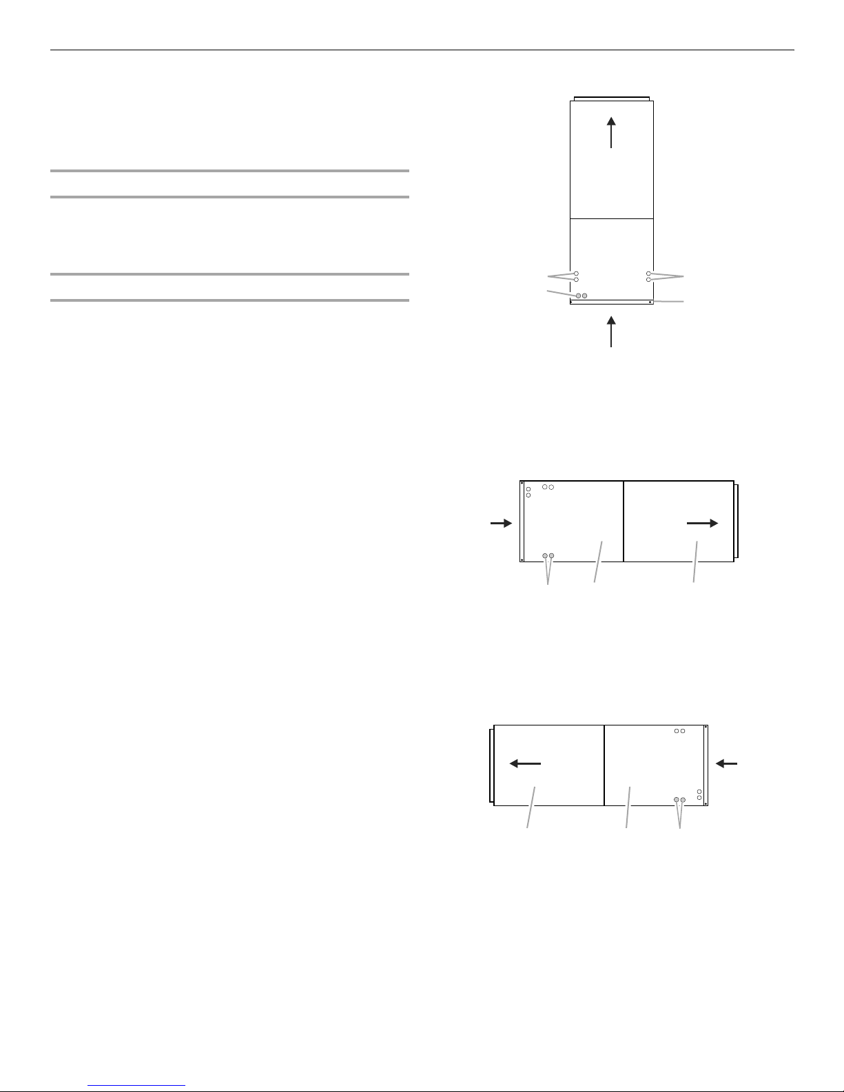
A
B
A. Horizontal drain connections
(left or right hand)
B. Upflow drain connection
C. Bottom/filter frame
Installation Configuration Options—Horizontal Right
NOTES:
■ Left to right airflow
■ As shipped from the factory
Drains
Suspended Cabinet Installation
NOTE: Air handlers cannot be installed horizontally lying on or
suspended from either the front or back of the air handler. It must
be positioned with one side parallel to the floor when in the
horizontal position.
The suspending means must be field fabricated, and should
consist of 2 “cradles” made by attaching 2 rods to a length of
angle iron or suitable gauge steel.
Installation Configuration Options—Upflow
NOTES:
■ As shipped from the factory.
■ Return in bottom.
■ Shading indicates proper line connections.
A
A. Drain connections
B. Coil access cover
C. Blower access cover
CB
Installation Configuration Options—Horizontal Left
■ Right to left airflow
■ Requires drain pan location change
A. Blower access cover
B. Coil access cover
C. Drain connections
.
Drains
BA
C
5
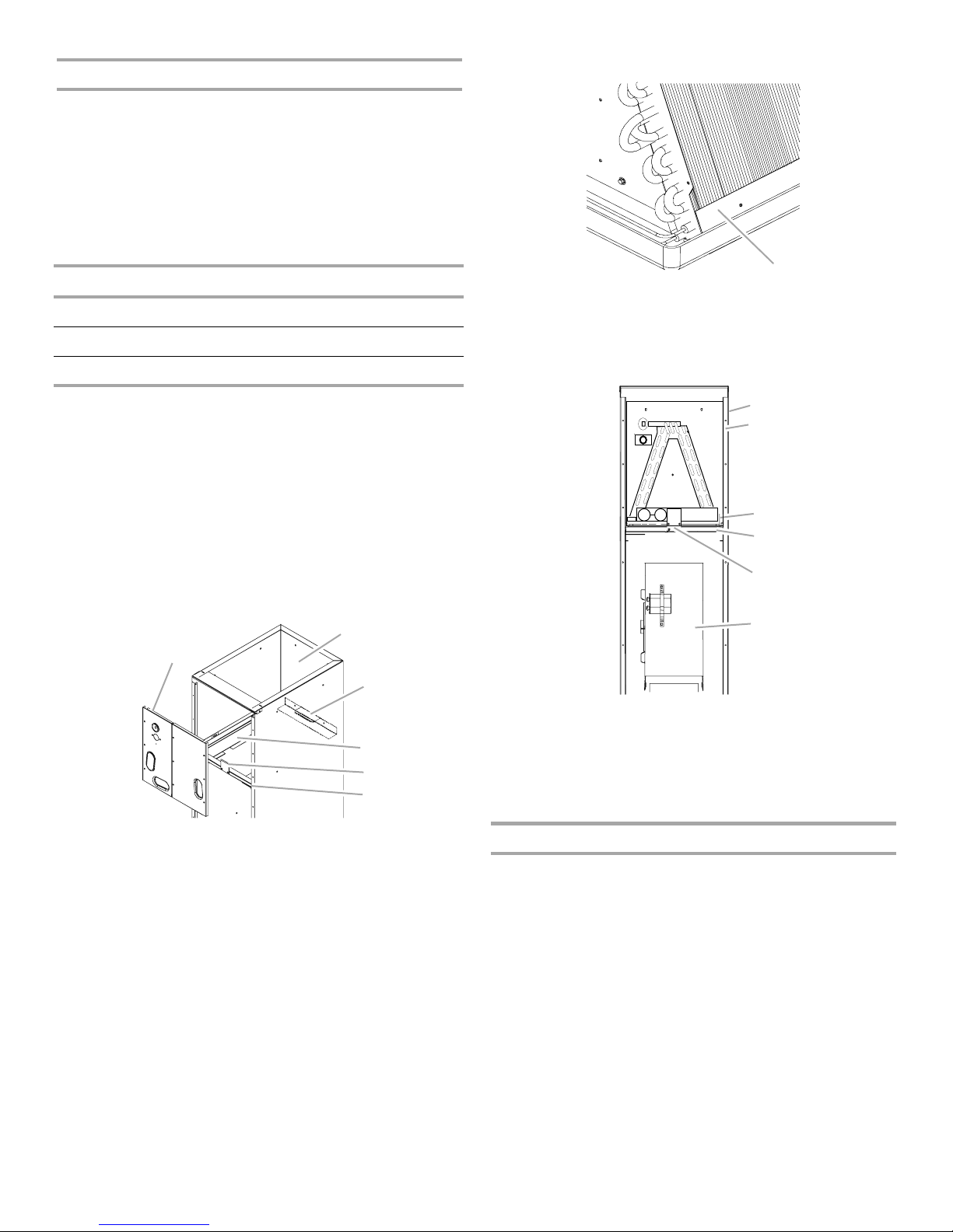
Downflow Conversion
C
D
E
F
A
B
C
D
E
“D” nomenclature models are factory equipped for dedicated
downflow operation and no field conversion is required.
Conversion to downflow must be performed in an area that
allows access to all sides prior to placing the air handler in its
final location. To keep the evaporator coil pan from sweating, the
DPI accessory insulation kit is to be used when performing this
conversion.
NOTE: The DPI kit is not supplied with this product and is to be
purchased separately. See the following chart for the correct DPI
kit.
WVAHM or WAHMS Model Insulation Kit
1824 DPI18-30/20
3030/1931/3636 DPI36-42/20
3642/3743/4860/4961 DPI48-61/20
1. Before inverting the air handler, remove all access panels, the
coil rear channel bracket, and the filter close-off panel.
2. Remove the evaporator coil and the horizontal drain pan.
3. Discard the horizontal drain pan.
4. Install the plastic plug (provided) into the vacated access
panel.
5. Remove the 2 zee coil support brackets and insulation
retaining brackets.
6. Remove the tie bracket.
7. Install the DPI Insulation Kit onto the bottom of the drain pan.
Evaporator Coil Pan
A
A. 3" (7.6 cm) flat insulation retainer (both sides)
To complete the conversion, slide the evaporator coil into the
chassis and attach the 3 access panels.
Evaporator Coil
Invert Air Handler
B
A
A. Access panel
B. Return air side of unit
C. Rear channel bracket
8. Install the zee coil supports and the wrapper stiffeners.
9. Install the tie bracket.
10. Install the rear channel bracket.
11. To avoid possible condensate “blow off,” the insulation
retainers are to be laid into the evaporator coil pan as shown
in the “Evaporator Coil Pan” illustration.
D. Zee coil support bracket
E. Coil retaining bracket
F. Tie b r ac k e t
F
A. Wrapper
B. Insulation jacket
C. Zee coil support
D. Wrapper stiffener
E. Drain pan insulation kit
F. Blower assembly
NOTE: When the air handler is converted to the downflow
position, the coil may protrude above the cabinet on some
models.
Horizontal Conversion
Dedicated downflow models are not suitable for horizontal
application and must not be used for this type of installation. The
only field modification required for conversion to “Horizontal
Right-Hand” is the removal of the plastic knockouts in the
horizontal panel drain connections. To keep the horizontal drain
pan from sweating in high humidity applications, it is
recommended that a DPIH insulation accessory kit be used.
6
 Loading...