

Page 1
INSTALLATION INSTRUCTIONS FOR
PACKAGE GAS ELECTRIC FURNACES
Table of Contents
GAS HEATING/ELECTRIC COOLING SAFETY ...........................1
INSTALLATION REQUIREMENTS................................................2
Tools and Parts ............................................................................2
Location Requirements................................................................3
Ductwork Requirements ..............................................................4
Electrical Requirements ...............................................................4
Gas Supply Requirements...........................................................4
FURNACE INSTALLATION INSTRUCTIONS ...............................5
Inspect Shipment......................................................................... 5
Place Furnace in Final Location...................................................5
Convert to Downflow ...................................................................6
Exhaust Vent Assembly ...............................................................6
Connect Condensate Drain .........................................................6
Install Ductwork............................................................................7
Make Electrical Connections .......................................................7
High Altitude Conversion .............................................................9
GAS HEATING/ELECTRIC COOLING SAFETY
Make Gas Connections................................................................9
Check the Furnace Input Rate ...................................................10
Adjust Manifold Pressure...........................................................10
Complete Installation..................................................................11
Adjust Blower Speed Multi-Speed Motor Only .........................11
Adjust Blower Speed Variable-Speed Motor Only ....................12
Measure Temperature Rise........................................................13
Shut Down..................................................................................13
SEQUENCE OF OPERATION ......................................................14
Cooling System ..........................................................................14
Heating System ..........................................................................14
Circulating Air Blower.................................................................14
Controls ......................................................................................15
TROUBLESHOOTING ..................................................................15
ASSISTANCE OR SERVICE.........................................................19
Accessories ................................................................................19
Your safety and the safety of others are very important.
We have provided many important safety messages in this manual and on your appliance. Always read and obey all safety
messages.
This is the safety alert symbol.
This symbol alerts you to potential hazards that can kill or hurt you and others.
All safety messages will follow the safety alert symbol and either the word “DANGER” or “WARNING.”
These words mean:
You can be killed or seriously injured if you don't immediately
DANGER
WARNING
All safety messages will tell you what the potential hazard is, tell you how to reduce the chance of injury, and tell you what can
happen if the instructions are not followed.
Whirlpool® Models
W2PG, W4PG
48289K005
Whirlpool® Home Cooling and Heating
follow instructions.
can be killed or seriously injured if you don't
You
instructions.
14610 Breakers Drive
Jacksonville, FL 32258
follow
Page 2
IMPORTANT SAFETY INSTRUCTIONS
■ Use only with type of gas approved for this furnace.
Refer to the furnace rating plate.
■ Install this furnace only in a location and position as
specified in the “Location Requirements” section of
these instructions.
■ Never test for gas leaks with an open flame. Use a
commercially available soap solution made
specifically for the detection of leaks to check all
■ Always install furnace to operate within the furnace’s
intended temperature-rise range with a duct system
which has an external static pressure within the
allowable range, as specified in the “Complete
Installation” section of these instructions.
See furnace rating plate.
■ The furnace is not to be used for temporary heating of
buildings or structures under construction.
connections, as specified in the “Make Gas
Connections” section of these instructions.
SAVE THESE INSTRUCTIONS
The California Safe Drinking Water and Toxic Enforcement Act requires the Governor of California to publish a list of substances
known to the State of California to cause cancer, birth defects, or other reproductive harm, and requires businesses to warn of
potential exposure to such substances.
WARNING: This product contains a chemical known to the State of California to cause cancer, birth defects, or other
reproductive harm.
This appliance can cause low-level exposure to some of the substances listed, including benzene, formaldehyde, carbon
monoxide, toluene, and soot.
ADDITIONAL SAFETY INFORMATION
In the State of Massachusetts, the following installation instructions apply:
■ Installations and repairs must be performed by a qualified or licensed contractor, plumber, or gasfitter qualified or licensed by
the State of Massachusetts.
■ If using a ball valve, it shall be a T-handle type.
■ A flexible gas connector, when used, must not exceed 3 feet.
INSTALLATION REQUIREMENTS
These instructions are intended as a general guide only for use by
qualified persons. Compliance with all local, state, or national
codes pertaining to this type of equipment should be determined
prior to installation.
Read this entire instruction manual, as well as the instructions
supplied in separate equipment, before starting the installation.
The installation of the furnace, wiring, warm air ducts, venting,
etc., must conform to the requirements of the National Fire
Protection Association; the National Fuel Gas Code, ANSI
Z223.1/NFPA No. 54 (latest edition) and the National Electrical
Code, ANSI/NFPA No. 70 (latest edition) in the United States, and
any state laws, local ordinances (including plumbing or
wastewater codes), or local gas utility requirements. Local
authorities having jurisdiction should be consulted before
installation is made. Such applicable regulations or requirements
take precedence over the general instructions in this manual.
Gather the required tools before starting installation. Read and
follow the instructions provided with any tools listed here.
Tools needed
■ Pipe wrenches
■ Screwdriver
■ Tape measure
■ Thread sealant
Parts needed
Check local codes and with gas supplier. Check existing gas
supply, electrical supply, and venting, and read “Electrical
Requirements,” “Gas Supply Requirements,” and “Ductwork
Requirements” before purchasing parts.
Tools and Parts
■ Noncorrosive leak detection solution
■ Test g auge w i th ¹⁄₈" NPT connection
(for measuring gas supply pressure)
2
Page 3

Location Requirements
WARNING
Explosion Hazard
Keep flammable materials and vapors, such as
gasoline, away from furnace.
Failure to follow these instructions can result in death,
explosion, or fire.
IMPORTANT: Do not use the furnace as a heater in a building
under construction. The furnace can be severely damaged due to
the abnormal environment caused by construction. Chlorides
from sources such as paint, stain, or varnish; tile and counter
cements; adhesives; and foam insulation are abundant in a
structure under construction and can be highly corrosive. Low
return air temperature can cause condensation in the furnace and
other damage that can shorten the life of the furnace.
■ This furnace is designed to be located outdoors with
sufficient clearance for free entrance to the inlet and
discharge air openings. The location must also allow for
adequate service access. See “Minimum Clearances.”
■ Where possible, select a location for the furnace which is
shaded from the direct rays of the sun most of the time. North
or east locations are usually most desirable. Position the
furnace to avoid direct contact with water, snow or ice from a
roofline overhead.
■ The furnace must be installed on a solid, level mounting pad
that will not settle or shift. Isolate the pad from the building
structure to avoid possible transmission of sound or vibration
from the furnace into the conditioned space.
■ The furnace foundation should be raised to a minimum of 3"
above finish grade. In areas which have prolonged periods of
temperature below freezing and snowfall, the furnace should
be elevated above the average snow line. If the furnace is to
be installed on a flat roof, it should be on a platform or other
support which will raise the base a minimum of 8" above the
surface of the flat roof.
■ This furnace can be installed on combustible Class A, Class
B or Class C roof covering material.
■ Avoid placing a furnace near areas such as sleeping quarters
or study rooms. Normal operating sound levels may be louder
than desired if the furnace is placed near certain rooms.
Minimum Clearances
Minimum - 0"
A
30"
36"
2"
B
30"
C
Recommended - 3"
24"
30"
Front side of unit
F
D
E
A. Supply air duct
B. Return air duct
C. Filter access panel
D. Evaporator coil access panel
E. Blower access panel
F. Burner access panel
Minimum Clearance Requirements
To
Combustible
Material
Front 24" 48" 24"
Rear 0" 24" 3"
Condenser
0" 24" 3"
End
Blower End 0" 30" 0"
Top 0" 36" 36"
For
Optimum
Service Access
For
Optimum
Operation
High Altitude Installations
■ This furnace is approved for operation at altitudes from 0 to
4,500 ft above sea level without any required modifications.
IMPORTANT:
For installations above 4,500 ft, the furnace input rate is to be
reduced per the requirements of the National Fuel Gas Code
(ANSI Z223.1/NFPA 54, latest edition), at the rate of 4 percent for
each 1,000 ft above sea level.
This furnace is not recommended for installation above 10,000 ft.
3
Page 4
Ductwork Requirements
■ Install all conditioned air plenums, ducts and air filters in
accordance with NFPA 90B Standard for the Installation of
Warm Air Heating and Air-Conditioning Systems (latest
edition).
■ The furnace is provided with flanges for the connection of the
plenum and ducts.
■ All air filters must be listed as Class 2 air filters.
■ All ductwork must be made of materials and insulated to
meet local, state and national codes. Ductwork installed
outdoors must be sealed, weatherproof and protected
against physical damage. Caulking, flashing or other means
of adequately providing a permanent weather seal should be
used where duct penetrates a building or structure opening.
Electrical Requirements
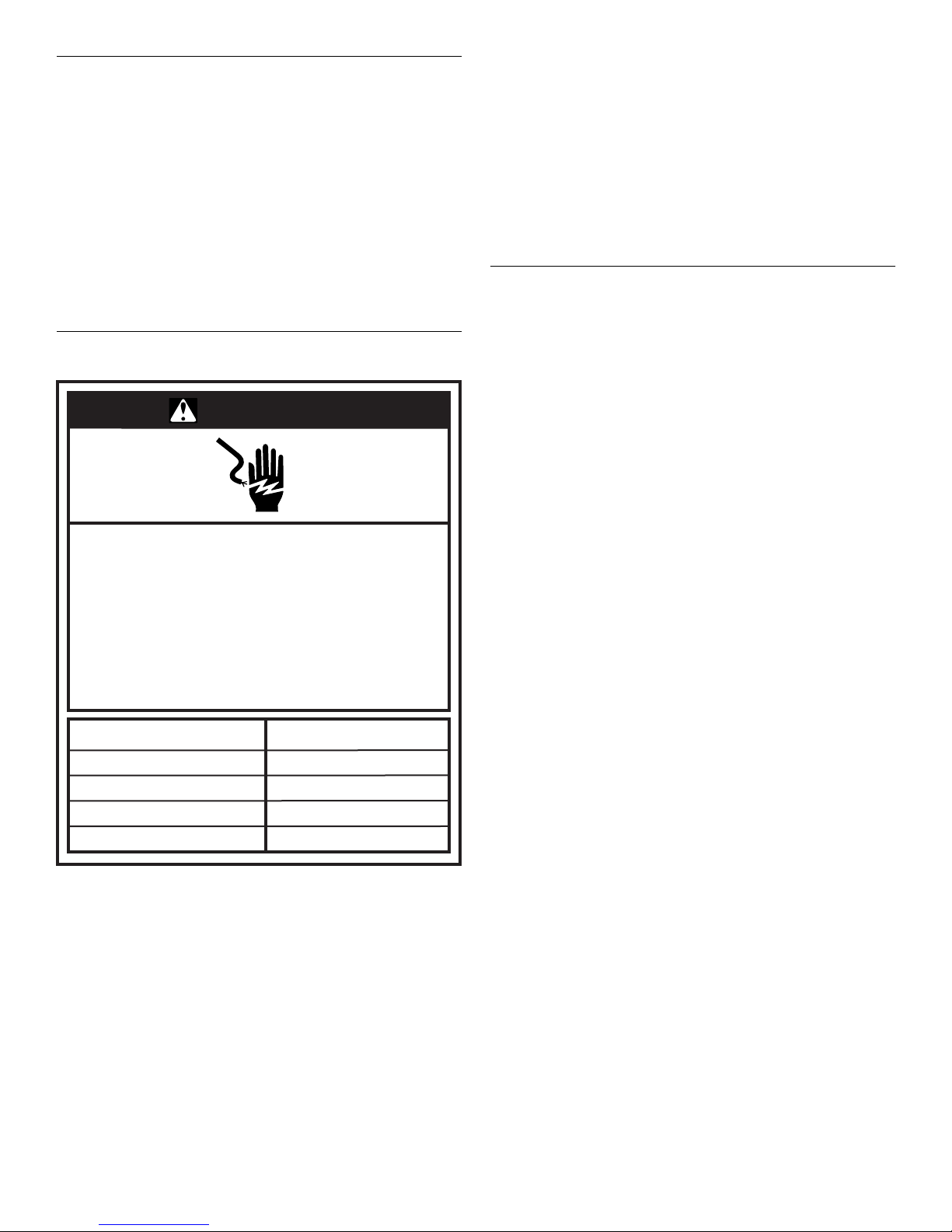
WARNING
■ All field wiring must be done in accordance with National
Electrical Code requirements, applicable requirements of UL,
or local codes, where applicable.
■ Electrical wiring, disconnect means and over current
protection are to be supplied by the installer. Refer to the
rating plate for the maximum over current protection,
minimum service ampacity, and operating voltage. See the
wiring connection diagrams in “Troubleshooting.”
■ This furnace must be electrically grounded in accordance
with National Electric Code (ANSI/NFPA 70) requirements,
applicable requirements of UL, or local codes, where
applicable.
Gas Supply Requirements
This furnace is equipped for use with Natural gas. A conversion
kit is required for use with propane. To order the correct
conversion kit, see “Accessories.”
■ Gas supply piping should be installed in accordance with
local, state and national codes and the regulations of the
utility. Piping must be of adequate size to prevent undue
pressure drop. Consult the local utility or gas supplier for
complete details on special requirements for sizing gas
piping.
■ If local codes allow the use of a flexible gas appliance
connector, use an CSA design-certified outdoor flexible
stainless steel appliance connector or rigid gas supply line as
needed.
Electrical Shock Hazard
Electrically ground furnace.
Connect ground wire to ground terminal
marked “GROUND”.
Use copper wire for supply connection.
Correct wire gauge is shown in the chart below.
Failure to follow these instructions can result in
death or electrical shock.
Rating Plate Ampacity
Less than 15
16 - 20
21 - 30
31 - 50 8
NOTE: All outdoor wiring must be suitable for outdoor use. Use
copper conductors only.
AWG
14
12
10
4
Page 5
FURNACE INSTALLATION INSTRUCTIONS
WARNING
Explosion Hazard
Furnace must be installed and serviced by a
qualified person.
Examples of a qualified person include:
licensed heating personnel,
authorized gas company personnel.
Read and follow all instructions provided for
installation, adjustment, service, alteration, or
maintenance.
Failure to follow these instructions can result in death,
explosion, fire, or carbon monoxide poisoning.
Inspect Shipment
WARNING
Excessive Weight Hazard
Use two or more people and mechanical equipment to
lift, move and install furnace.
Failure to do so can result in back or other injury.
Place Furnace in Final Location
WARNING
Excessive Weight Hazard
Use two or more people and mechanical equipment to
lift, move and install furnace.
Failure to do so can result in back or other injury.
IMPORTANT: Place the furnace in the final location and position
it in the proper orientation to the house so that connecting ducts,
electrical and gas supplies is easily done. Hoisting may be
required.
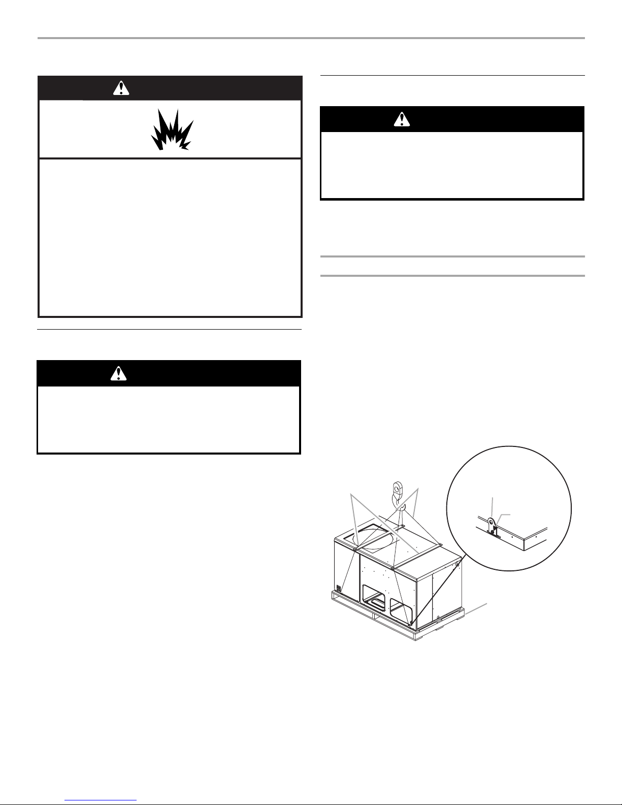
Hoisting
An accessory lift kit must be purchased to hoist the furnace. See
“Accessories.” Attach the rigging to the lifting brackets on each
corner.
NOTE: All access panels must be secured in place before
hoisting.
The furnace should be hoisted with 2 lifting slings. Attach the
slings to rigging shackles that have been hooked through holes in
the lifting brackets.
Place 2 spreaders on top of the furnace to protect the furnace
from damage from the pressure exerted by the slings. Make sure
that all equipment is rated to handle at least 750 lbs and that the
slings will not allow the furnace to shift. See “Typical Sling
Configuration.”
Typical Sling Configuration
This furnace is shipped in one package, completely assembled
and wired. The indoor thermostat and accessories are shipped in
a separate carton when ordered.
1. Check the furnace rating plate to confirm specifications are
as ordered.
2. Upon receipt of equipment, inspect it for possible shipping
damage. Be sure to examine the furnace inside the carton if
the carton is damaged.
If damage is found, it should be noted on the carrier’s freight bill.
Damage claims should be filed with the carrier immediately.
Claims of shortages should be filed with the seller within 5 days.
NOTE: If any damages are discovered and reported to the carrier,
do not install the furnace as your claim may be denied.
A
A. Spreaders
B. Pallet
C. Cables
C
D
E
B
D. Lifting bracket
(accessory lift kit)
E. Sheet metal screw
5
Page 6
Convert to Downflow
B
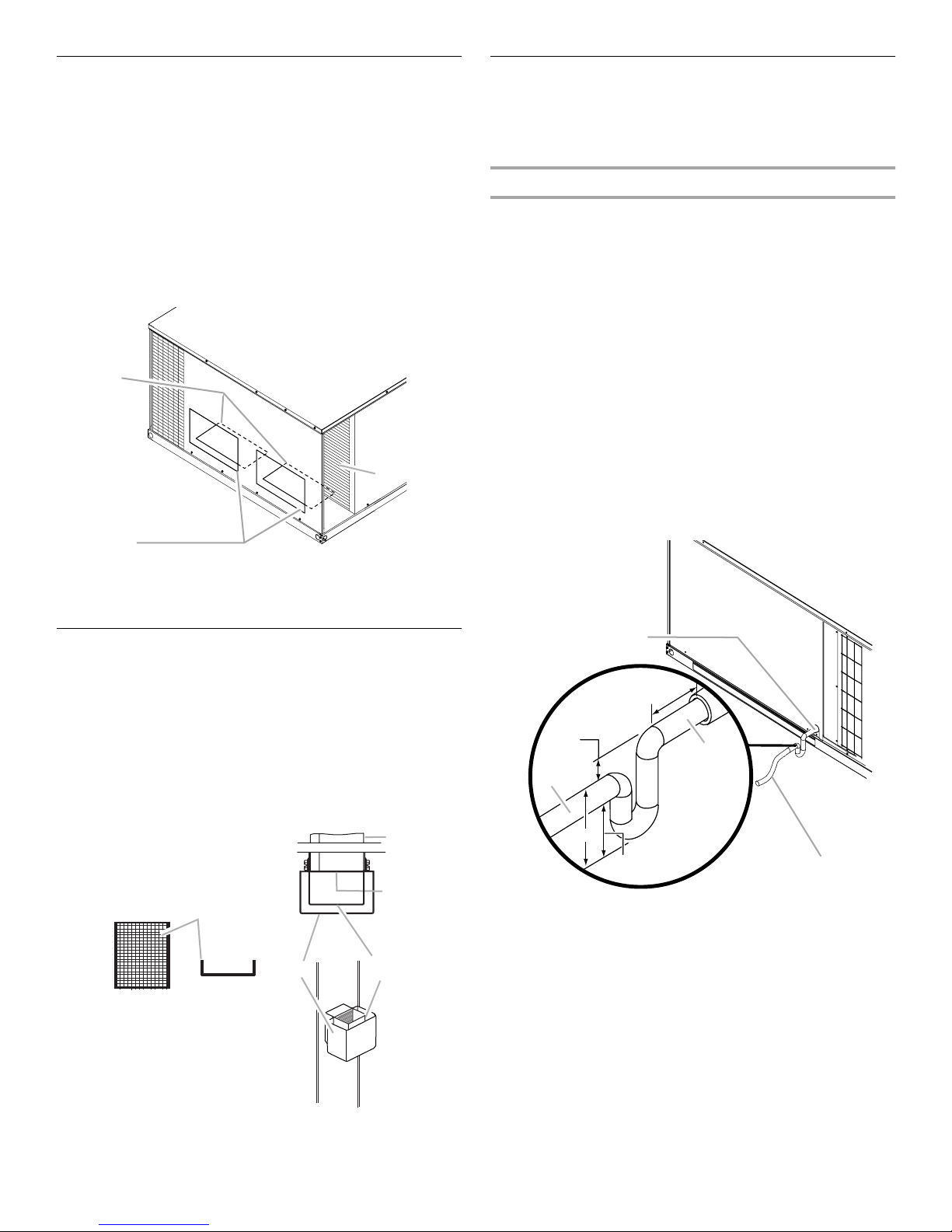
This furnace is factory-built for horizontal airflow applications and
may also be field-converted for downflow use.
To convert to downflow use:
1. Remove the filter access panel.
2. Remove the two downflow duct cover plates (one screw and
tab for each) found in the return and supply air
compartments.
3. Using eight #10 x ³⁄₄" screws (field supplied), install the
previously removed duct covers on the horizontal return and
supply air openings. Use the pilot holes provided.
4. Reinstall the filter access panel.
B
A
C
Connect Condensate Drain
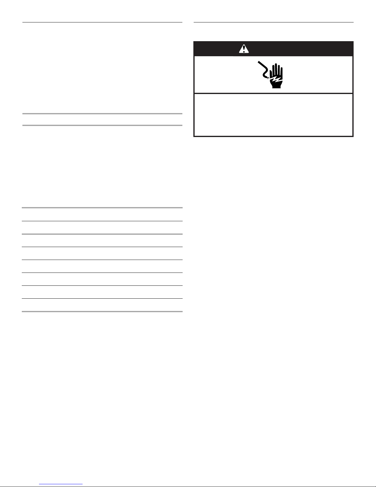
The condensate drain outlet is a ³⁄₄" threaded PVC fitting located
at the bottom on the side of the furnace. A ³⁄₄" drain line with trap
must be installed on all applications to avoid accumulation of
condensate under or around the furnace.
Install Condensate Trap
1. Construct the condensate trap from PVC tubing as shown in
“Condensate Trap Construction.”
NOTES:
■ The condensate trap allows a standing column of water of
at least 2" (50 mm).
■ The top of the drain trap inlet must be at least least 1"
(25 mm) above the top of the drain trap outlet.
■ The trap should be installed as close to the furnace as
possible, while still providing proper drainage.
■ For service access, do not block heat exchanger access
panel or the filter access panel with the drain line.
2. Thread the drain assembly into the ³⁄₄" PVC fitting.
NOTE: Do not glue the threaded fitting so it can be removed
during servicing of unit.
3. Run the drain line to an open drain or other suitable disposal
point.
Condensate Trap Construction
A. Filter access panel
B. Horizontal return and supply air openings
C. Downflow duct cover plates
Exhaust Vent Assembly
1. Place the screen over the exhaust port.
2. Place the internal vent hood over the exhaust port.
3. Place the outer cover over the internal vent hood and exhaust
port.
4. Align the screw holes in the covers with the holes in the
exhaust port.
5. Attach the covers using the four #10 screws provided.
Front View
A
Preformed
Top View
A
D
C
A
12" Max.
1" Min.
C
D
3" Min.
2" Min.
A.
³⁄₄
" PVC fitting (threaded) drain condensate connection
B.
³⁄₄
" drain pipes, field provided
C. Drain trap outlet
D. Drain trap inlet
B
A. Screen
B. Exhaust port
C. Internal vent hood—slotted side
faces condenser coil
D. Outer cover
6
Page 7
Install Ductwork
■ Install ductwork in accordance with NFPA 90B and any local
codes.
■ The use of flexible, noncombustible connectors between the
main trunk ducts and the supply and return air plenums is
recommended to minimize vibration transmission.
■ Plenums must be individually sealed to furnace casing with
ducts terminating inside the structure.
■ Flashing used to cover ductwork must permit removal of
access panels and top. See “Minimum Clearances” in the
“Locations Requirements” section.
Filters
Filters are not supplied with these furnaces; however, filters must
be used. It is the installer’s responsibility to install a filter rack with
the ductwork and to install properly sized filters in accordance
with the Minimum Required Surface Area for Disposable Filters
chart.
All return air must pass through a filter before entering the
furnace. An electronic air cleaner, filter rack or other accessible
filter arrangement must be installed in the return air ductwork.
Minimum recommended filter areas are listed in the Minimum
Required Surface Area for Disposable Filters chart, and are
based on a face velocity of 325 ft (99.1 m) per min. for disposable
filters and 525 ft (160 m) per min. for cleanable filters.
Minimum Required Surface Area for Disposable Filters
Nominal Cooling Filter Area (sq. ft)
24,000 2.67
30,000 3.33
36,000 4.00
42,000 4.67
Make Electrical Connections
WARNING
Electrical Shock Hazard
Disconnect power before servicing.
Replace all parts and panels before operating.
Failure to do so can result in death or electrical shock.
IMPORTANT:
■ Electrical wiring, disconnect means and over-current
protection are to be supplied by the installer. Refer to the
rating plate for the maximum over-current protection,
minimum circuit ampacity and operating voltage. See the
wiring connection diagrams in “Troubleshooting.”
■ Install an adequate sized branch circuit disconnect,
according to the NEC, within sight of and readily accessible
to furnace.
■ The cable or conduit and fittings connected from the
disconnect switch to the furnace wiring connections shall be
rated for outdoor use.
■ Check the furnace rating plate to determine whether the
system is rated single phase or three phase and follow the
appropriate instructions for connecting the pigtail leads.
■ Plug unused side entry holes with field-supplied plugs to
prevent moisture from entering the furnace.
■ Low voltage wiring must be separated from line voltage
wiring.
48,000 5.33
60,000 6.67
7
Page 8
Line Voltage Connections
WARNING
Electrical Shock Hazard
Electrically ground furnace.
Connect ground wire to ground terminal
marked “GROUND”.
Use copper wire for supply connection.
Correct wire gauge is shown in the chart below.
Failure to follow these instructions can result in
death or electrical shock.
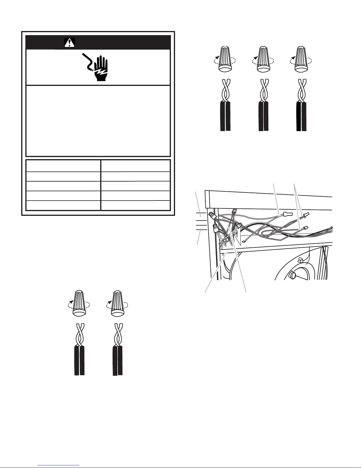
For three phase units:
■ Connect the field supply wires (L1, L2, L3) to the 3 black
pigtail leads using UL listed wire nuts.
NOTE: Check compressor operation for proper rotation. If the
rotation is not correct, then reverse any two leads (for example:
L1 and L2). Incorrect rotation is identified by excessive sound or
improper system pressures.
Rating Plate Ampacity
Less than 15
16 - 20
21 - 30
31 - 50 8
1. Disconnect power.
2. Remove the blower access panel.
3. Remove the burner access panel.
4. Route the field supply wires through the line voltage conduit
opening to the electrical connection area, providing sufficient
length to connect to the pigtail leads.
5. For single phase units:
■ Connect the field supply wires (L1, L2) to the 2 black
pigtail leads using UL listed wire nuts.
AWG
14
12
10
Line and Low Voltage Connections
B
A
F
E
A. Line voltage supply conduit
B. Ground terminal connection
C. Line voltage field supply
connections
1. Route the low voltage supply wires through the low voltage
entry opening to the low voltage connection area providing
sufficient length to connect to the low voltage pigtail leads.
2. Using UL listed wire nuts, connect the low voltage supply
wires to the matching colors of the low voltage leads.
3. Replace the burner access panel.
4. Replace the blower access panel.
D
D. Low voltage connections
E. Electrical connection box
F. Low voltage supply conduit
C
8
Page 9
208 Volt Conversion
D
WARNING
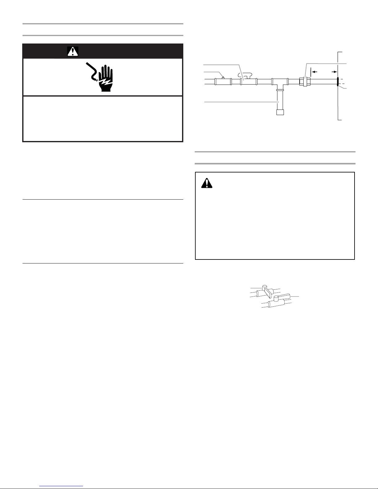
Side entry is the usual method of routing the gas supply to the
unit. Use the factory provided grommet to seal the opening
around the gas pipe preventing rain and moisture from entering
the unit around the gas pipe and reduce noise.
A
B
6" Min.
E
Electrical Shock Hazard
Disconnect power before servicing.
Replace all parts and panels before operating.
Failure to do so can result in death or electrical shock.
1. Disconnect power.
2. Remove the burner access panel.
3. Move the black wire lead from the 240-volt terminal on the
transformer to the 208-volt terminal (center tap) on the
transformer. See the wiring connection diagrams in
“Troubleshooting.”
4. Replace the burner access panel.
High Altitude Conversion
(if required)
Ratings are shown on the rating plate for elevations up to
4,500 ft. For elevations above 4,500 ft, ratings should be reduced
at a rate of 4 percent for each 1,000 ft above sea level. See the
National Fuel Gas Code Z223.1 (latest edition) or the Canadian
Installation Codes CAN/CGA-B149.1 and B149.2 for further
details. Not recommended for over 10,000 ft.
Make Gas Connections
IMPORTANT: This furnace requires conversion for use with
propane. To order the correct conversion kit, see “Accessories.”
1. Provide a sediment trap on the outside of the furnace section.
2. Install a manual gas shutoff valve in the gas line, outside the
unit in accordance with any local codes.
3. Install a test gauge connection with a ¹⁄₈" NPT plugged
tapping immediately upstream of the manual gas shutoff
valve as shown.
Connect the gas pipe to the furnace gas valve threaded fitting
provided, installing a ground joint union as close to the controls
as possible to facilitate removal of controls and manifold. Pipejoint compounds suitable for use with Natural and LP gas must
be used. Do not use Teflon
®†
tape.
C
A. Manual gas shutoff valve
B.
¹⁄₈
" NPT plugged tapping
C. Sediment trap
D. Ground joint union
E. Grommet
Check Inlet Pressure
WARNING
FIRE OR EXPLOSION HAZARD
Failure to follow the safety warnings exactly could result
in serious injury, death or property damage.
Never test for gas leaks with an open flame. Use a
commercially available soap solution made specifically
for the detection of leaks to check all connections. A fire
or explosion may result causing property damage,
personal injury or loss of life.
1. Remove the burner access panel.
2. Turn off the gas supply at the manual gas shutoff valve.
A
B
A. Closed valve
B. Open valve
3. Remove the inlet pressure tap plug on the gas control valve.
Install a ¹⁄₈" NPT hose connector and connect the pressure
gauge tube.
†®Teflon is a registered trademark of E.I. Dupont de Nemours and
Company.
9
Page 10
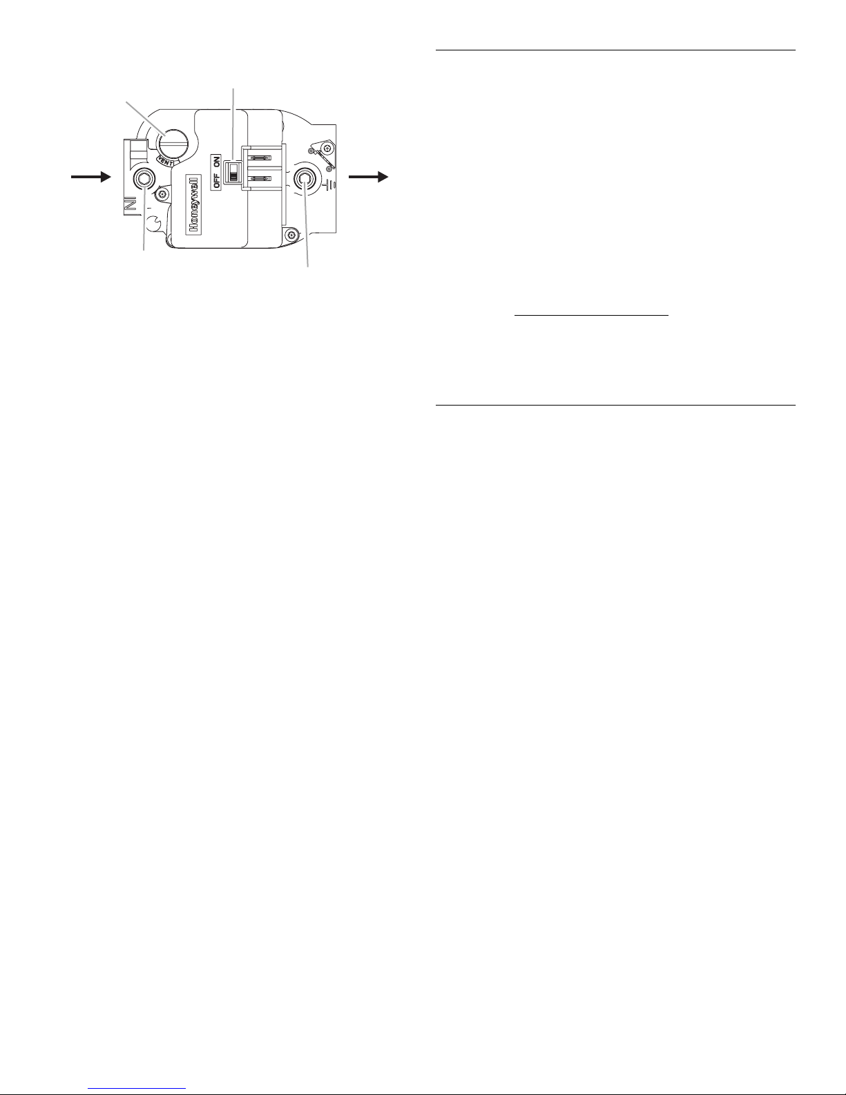
Gas Control Valve
E
F
A
B
C
D
A. Regulator adjusting cap
B. NPT inlet
¹⁄₈
" NPT inlet pressure tap
C.
4. Turn on the gas supply at the manual gas shutoff valve. Set
the room thermostat to a point above room temperature to
light the main burners.
NOTE: This furnace is equipped with an ignition device,
which automatically lights the burner. This furnace cannot be
lighted manually. Do not try to light the burner by hand.
5. Turn on the electrical power to the furnace.
6. Check minimum inlet gas supply pressure.
■ Turn on all other gas appliances.
■ Observe the pressure rating on the pressure gauge.
■ The minimum inlet gas supply pressure is 5" W.C. for
Natural gas and 11" W.C. for propane gas.
7. Check maximum inlet gas supply pressure.
■ Turn off all other gas appliances.
■ Observe the pressure reading on the pressure gauge.
■ The maximum inlet gas supply pressure is 10.5" W.C. for
Natural gas and 13" W.C. for propane gas.
IMPORTANT: If the inlet gas supply pressure is not within the
minimum and maximum range as shown on the rating plate,
contact your gas supplier.
8. Turn off the electrical power to the furnace.
9. Turn off the gas supply at the manual gas shutoff valve.
Remove the pressure gauge tube and the ¹⁄₈" hose connector.
10. Replace the inlet pressure tap plug on the gas control valve.
11. Turn on the gas supply at the manual gas shutoff valve.
12. Test all connections by brushing on an approved
noncorrosive leak-detection solution. Bubbles will show a
leak. Correct any leak found.
■ At test pressures greater than ¹⁄₂ psig (3.5 kPa), the
furnace and the manual gas shutoff valve must be
disconnected from the gas supply piping system.
■ At test pressures less than or equal to ¹⁄₂ psig (3.5 kPa),
the furnace must be isolated from the gas supply piping
system by closing the manual gas shutoff valve.
13. Replace the burner access panel.
D.
¹⁄₈
" NPT outlet pressure tap
E. NPT outlet
F. Gas control switch
Check the Furnace Input Rate
(if required)
IMPORTANT:
■ The furnace input rate must not exceed the input rating on
the furnace rating plate.
■ This furnace is equipped for rated input at manifold pressures
of 3.5" W.C. for Natural gas and 11.0" W.C. for propane gas.
■ At altitudes above 4,500 ft the furnace input rate must not
exceed that on the furnace rating plate reduced by 4 percent
for each 1,000 ft above sea level.
1. For Natural gas, check the furnace rate by observing the gas
meter, making sure all other gas appliances are turned off.
The test hand on the meter should be timed for at least one
revolution.
BTU/HR
INPUT
2. The actual heating value of your gas can be obtained from
your local utility company.
NOTE: If the input exceeds the input rating on the furnace rating
plate, adjust the manifold pressure.
= Cubic feet per Revolution x 3600 x Heating
# Seconds per Revolution
Value
Adjust Manifold Pressure
1. Remove the burner access panel.
2. Turn off the gas supply at the manual gas shutoff valve. Use
only your hand to move the gas control knob; tools are not
required.
3. Remove the outlet pressure tap plug on the gas control valve
and connect pressure gauge to the ¹⁄₈" NPT outlet pressure
tap.
4. Be sure the manual gas shutoff valve has been in the Off
position for at least 5 minutes before starting the furnace.
5. Turn on the gas supply at the manual gas shutoff valve.
NOTE: This furnace is equipped with an ignition device,
which automatically lights the burner. This furnace cannot be
lighted manually. Do not try to light the burner by hand.
6. Turn on the electrical power to the furnace.
7. Set the room thermostat to a point above room temperature
to light the main burners.
8. Observe the pressure reading on the pressure gauge.
9. Refer to the rating plate for the correct manifold pressure. If
necessary, remove the regulator adjusting cap on the gas
valve and turn the regulator adjusting screw clockwise to
increase pressure, or counterclockwise to decrease pressure.
IMPORTANT: If the manifold pressure cannot be adjusted to
the value on the furnace rating plate, contact your gas
supplier.
10. Turn off the gas supply at the manual gas shutoff valve.
11. Disconnect the pressure gauge from the ¹⁄₈" NPT outlet
pressure tap.
12. Replace outlet pressure tap plug and the regulator adjusting
cap on the gas valve.
10
Page 11
13. Turn on the gas supply at the manual gas shutoff valve.
14. Replace the burner access panel.
15. Set the room thermostat to the desired temperature.
Adjust Blower Speed Multi-Speed Motor Only
Manifold Pressure vs. Altitude Chart
Natural Gas
Heating Value
Altitude (ft)
2,000 948 3.50 0.9666
3,000 914 3.50 0.9499
4,000 881 3.50 0.9332
4,500 865 3.50 0.9249
5,000 849 3.29 0.8900
5,500 833 3.27 0.8790
6,000 818 3.25 0.8680
6,500 802 3.23 0.8570
7,000 787 3.21 0.8460
7,500 771 3.19 0.8350
(Btu/ft
3
)
Manifold
Pressure
(in. W.C.) Input Factor
For altitudes 7,500 to 10,000 ft above sea level
Do not adjust manifold pressure. An orifice change is required.
For the correct orifice size, see Table F.4 in Appendix F of the
National Fuel Gas Code (ANSI Z223.1/NFPA 54, latest edition).
Complete Installation
IMPORTANT: Do not use this furnace if any part has been under
water. Immediately call a qualified person to inspect the furnace
and to replace any part of the control system and gas control
which has been under water.
1. Check to be sure you have all of your tools.
2. Dispose of/recycle all packaging materials.
3. Check the furnace in its final location. Be sure the exhaust
vent is not blocked.
WARNING
Electrical Shock Hazard
Disconnect power before servicing.
Replace all parts and panels before operating.
Failure to do so can result in death or electrical shock.
You can choose the same speed or different speeds for COOL or
HEAT.
NOTE: See the wiring connection diagrams in “Troubleshooting.”
1. If the temperature rise is too high, change the speed tap to
one step higher.
2. If the temperature rise is too low, change the speed tap to
one step lower.
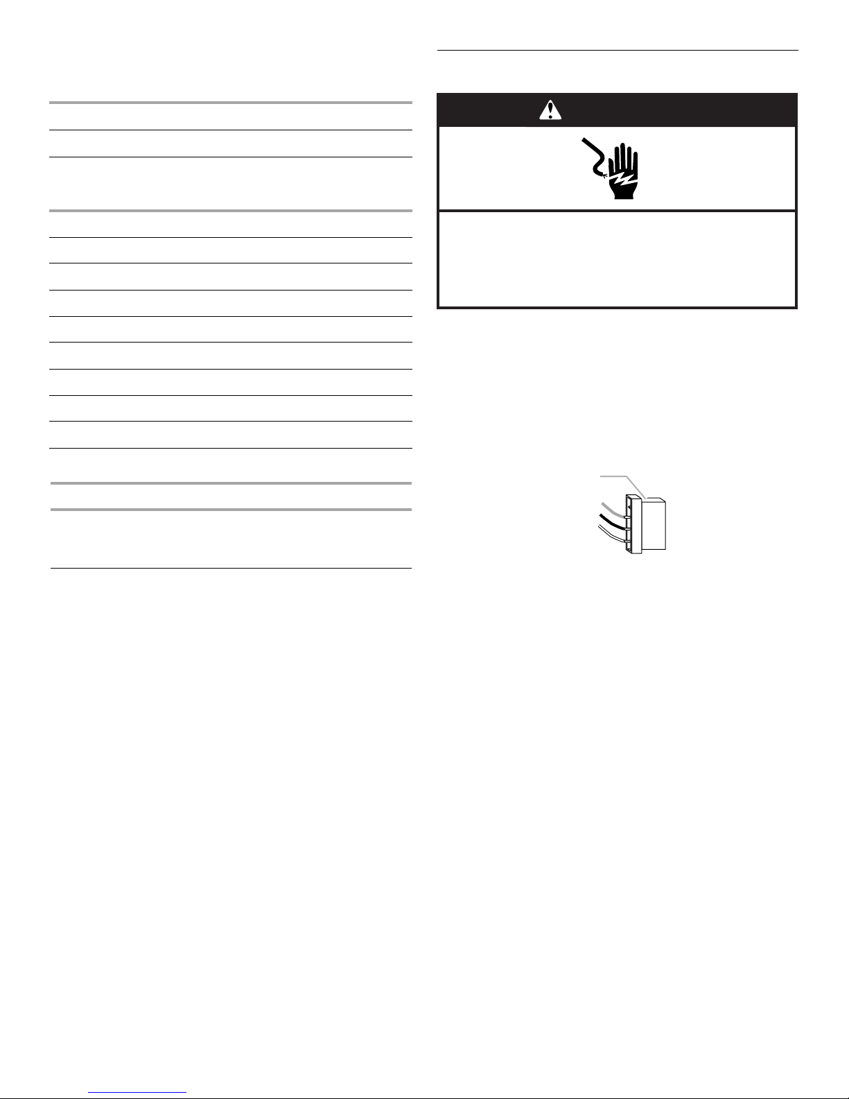
Blower Speed Tap Change
A
Red
Blue
White
A. Blower motor connector
LOW
MED
HIGH
COM
11
Page 12
To Select the Same Speed for COOL and HEAT
NOTE: Some models have the same speed for COOL and HEAT
already connected.
At the Blower Motor Connector
1. Disconnect power.
2. Remove blower and burner access panels.
3. Place black wire on the HIGH, MED or LOW motor speed tap,
as desired.
4. Place blue wire on any of the other motor speed taps.
At the Furnace Control Board
1. Remove the blue and black wires from the HEAT and COOL
terminals and the black jumper wire from the UNUSED
terminal.
2. Connect the blue wire to the UNUSED terminal.
3. Connect the black jumper wire (piggyback end) to the COOL
terminal.
4. Connect the other end of the black jumper wire to the HEAT
terminal.
5. Connect the black wire to the black jumper wire (piggyback
end) on the COOL terminal.
6. Replace the blower and burner access panels.
7. Reconnect power.
To Select Different Speeds for COOL and HEAT
At the Blower Motor Connector
1. Disconnect power.
2. Remove blower and burner access panels.
3. Place black wire on the HIGH, MED or LOW motor speed tap,
as desired for COOLING.
4. Place blue wire on any of the other motor speed taps for
HEATING.
At the Unit Control Board
1. Place blue wire on the COOL terminal.
2. Place red wire on the HEAT terminal.
3. Replace blower and burner access panels.
4. Reconnect power.
Blower Speed Chart for Multi-Speed Motor
Unit Factory-Shipped Settings
Cooling Input Heating Input Heat (BU) Cool (BK)
24 68 MED LOW
30 68 MED MED
36 68 MED HIGH
36 90 HIGH HIGH
42 83 LOW LOW
42 110 LOW LOW
48 83 LOW MED
48 110 LOW MED
48 138 MED MED
60 83 LOW HIGH
60 110 LOW HIGH
60 138 MED HIGH
Adjust Blower Speed Variable-Speed Motor Only
WARNING
Electrical Shock Hazard
Disconnect power before servicing.
Replace all parts and panels before operating.
Failure to do so can result in death or electrical shock.
Circulation Airflow Adjustments
The controls include a variable-speed motor interface board. The
ADJUST tap can be used to raise (+) or lower (-) the airflow by
15 percent.
Heating and Cooling Airflows
The units are factory-set for the correct heating and cooling
airflows. However, airflow changes can be made by moving the
position of the HEAT and COOL taps. See Adjusting Airflow for
Variable-Speed Motor chart.
Continuous Blower
The comfort level of the living space can be enhanced when
using this feature by allowing continuous circulation of air
between calls for cooling or heating. The continuous circulation
of air occurs at half the full cooling airflow rate. To use this
feature, place the thermostat fan switch into the On position.
Cooling Airflow Ramp Up
At the beginning of a call for cooling, the blower will run at
80 percent of full airflow for 7.5 minutes. This improves the
system’s moisture removal and saves blower power during
cooling start.
Reduced Airflow Operation (Dehumidification)
For situations where humidity control is an issue, the variablespeed motor can be connected to operate at a 25 percent
reduction in the normal airflow rate. The variable-speed motor
interface board provides for connection of a humidistat on the
HUM terminal. When a humidistat is connected, the dehumidifier
resistor on the interface must be cut. The humidistat should be
wired to open during high humidity, which will reduce blower
airflow.
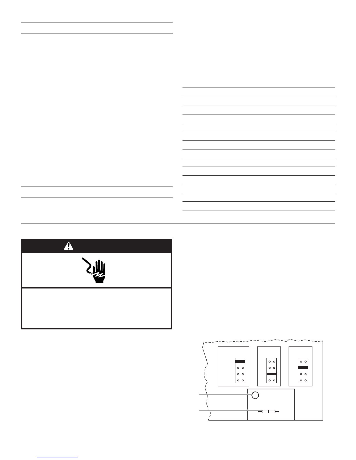
ADJUST, HEAT, and COOL Taps and Dehumidify Resistor
COOLHEATADJUST
NORM A
(+)
(–)
TEST
A
B
A. Dehumidify LED
B. Dehumidify resistor
A
B
C
D
D1
DEHUMIDIFY
CUT TO ENABLE
B
C
D
12
Page 13
Adjusting Airflow for Variable-Speed Motor
E
Model
Nominal
Cooling
kBTU
24, 30 68 ¹⁄₃ NORM A 1,000 800 600 900
36 68 ¹⁄₂ NORM B 1,200 1,000 800 1,100
36 90 ¹⁄₂ NORM A 1,200 1,000 800 1,100
42, 48, 60 83 ³⁄₄ NORM C 1,800 1,600 1,400 1,200
42, 48, 60 110 ³⁄₄ NORM C 1,800 1,600 1,400 1,200
42, 48, 60 138 ³⁄₄ NORM A 1,800 1,600 1,400 1,200
Heating
Input
kBTU
Motor HPADJUST
Setting
HEAT
Setting
Blower Speed Chart for Variable-Speed Motor
Unit Factory-Shipped Settings
Cooling
Input
24 68 NORM A B
30 68 NORM A A
36 68 NORM B A
36 90 NORM A A
Heating
Input Adjust
Heat
(BU)
Cool
(BK)
1. After 20 minutes of heating operation, measure the furnace
2. If the furnace doesn't maintain temperature rise within the
Cooling CFM @ .50 Static
COOL
Setting A
COOL
Setting B
COOL
Setting C
COOL
Setting D
Measure Temperature Rise
temperature rise. Take air temperature readings in both the
return air ducts and the heated air ducts.
NOTE: If more than one run of return or heated air ducts is
used, air temperature measurements should be taken in each
duct. These measurements can be converted to an average
to obtain the temperature rise of the whole system.
range shown on the furnace rating plate, adjust the blower
speed. See the appropriate “Adjust Blower Speed” section
for your model.
42 83 NORM C C
42 110 NORM C C
48 83 NORM C B
48 110 NORM C B
48 138 NORM A B
60 83 NORM C A
60 110 NORM C A
60 138 NORM A A
Shut Down
If the construction will continue or the package unit will not be
used for a period of time, follow the shut down procedure.
1. Set the room thermostat to the lowest setting.
2. Disconnect power.
3. Remove burner access panel.
4. Turn off the gas supply at the manual gas shutoff valve.
5. Replace the burner access panel.
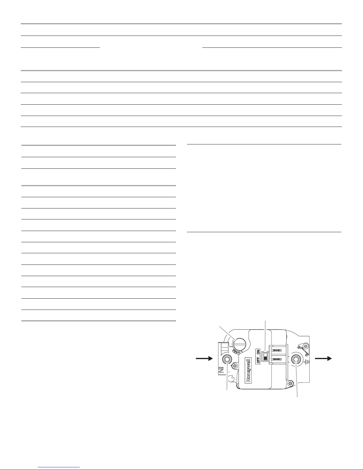
Gas Control Valve
F
A
B
C
D
A. Regulator adjusting cap
B. NPT inlet
C.
¹⁄₈
" NPT inlet pressure tap
¹⁄₈
" NPT outlet pressure tap
D.
E. NPT outlet
F. Gas control switch
13
Page 14

SEQUENCE OF OPERATION
Cooling System
The cooling system is a complete factory package utilizing an aircooled condenser. The compressor is hermetically-sealed and
base-mounted with rubber-insulated hold-down bolts.
Furnace compressors have internal protection. In the event there
is an abnormal rise in the temperature of the compressor, the
protector will open and cause the compressor to stop.
Cooling Sequence of Operation
When the thermostat calls for cooling, R is closed to G and Y.
See the wiring connection diagrams in “Troubleshooting.” This
action completes the low voltage control circuit, energizing the
compressor, condenser fan motor and blower motor.
Blower Delay—Cooling
The circulating air blower is controlled by a timing circuit in the
integrated blower/ignition control. Timings are not adjustable.
Blower “on” delay is 5 seconds after the compressor starts and
blower “off” timing is 90 seconds after the cooling system shuts
down.
System Performance
For maximum performance of the cooling system, operating
temperatures and pressure should be checked. Superheat
should be determined at Standard ARI test conditions of 82ºF
(27.8ºC) outdoor and 80ºF (26.7ºC) indoor dry bulb/67ºF (19.4ºC)
wet bulb. If superheat measured deviates from values found in
the Suction Superheat table, refrigerant charge should be
adjusted accordingly for maximum performance.
Suction Superheat
Suction Superheat
@ ARI Conditions
82ºF (27.8ºC) OD /
Series Size
PGE/SG13
PGEX/SGX15
24 22º
30, 36, 42, 48, 60 20º
24, 30 15º
36, 42 12º
48, 60 10º
80ºF (26.7ºC) IDDB/
67ºF (19.4ºC) IDWB
Heating System
With the proper thermostat and subbase, continuous blower
operation is possible by closing the R to G circuit. Cooling blower
delay is also functional in this mode.
Heating Sequence of operation
1. When the thermostat calls for heat, the combustion blower is
energized by the ignition control.
2. When the speed of the combustion blower reaches proper
RPM, the pressure switch closes, initiating the pre-purge
timing (30 seconds nominal).
3. When pre-purge has expired, the ignition control energizes
the gas control valve, the spark electrode and the flame
sensor. The igniter sparks for 10 seconds, and the flame
sensor senses that flame has been established. If the flame
sensor does not sense that flame has been established in the
10-second interval, the ignition control will de-energize the
gas control valve.
4. The ignition control is designed to repeat this “trial for
ignition” a total of three times. If, at the end of the third trial, a
flame still has not been established, the ignition control will
repeat the trial for ignition sequence 1 hour later. The 1-hour
retry is indefinite.
5. Thirty seconds (nominal) after the initial trial for ignition, the
circulation air blower will start.
6. When the thermostat is satisfied, the combustion blower and
gas control valve are de-energized. The circulating air blower
motor will continue to run for a short period after the
thermostat is satisfied.
Circulating Air Blower
Depending on the package unit model, the blower motor will be
either a multi-speed or variable-speed motor.
Multi-Speed Motor
The circulating air blower is controlled by a timing circuit in the
integrated blower/ignition control. Timings are not adjustable.
Cooling
Blower “on” delay is 30 seconds after call for cooling. Blower
“off” delay is 90 seconds after the cooling system shuts down.
Heating
Blower “on” delay is 30 seconds (nominal) after burner ignition.
Blower “off” delay is approximately 120 seconds after the
thermostat is satisfied.
14
Page 15
Variable-Speed Motor
Pressure Switch
Units equipped with a variable-speed circulation air blower motor
will deliver a constant airflow within a wide range of external
static pressures. For other features of this variable-speed motor,
see “Adjust Blower Speed Variable-Speed Motor Only.”
Start/Stop
The variable-speed motor will slowly ramp up to normal
operating speed. This minimizes noise and increases comfort by
eliminating the initial blasts of air encountered with standard
motors. At the end of a cooling or heating cycle, the motor will
slowly ramp down.
Controls
Limit Control
This control is located inside the heating compartment and is
designed to open at abnormally high air temperatures. It resets
automatically. The limit control operates when a high temperature
condition, caused by inadequate airflow, occurs. This causes the
ignition control to close the gas control valve. The circulation air
blower continues to operate in this situation.
TROUBLESHOOTING
Furnace Fails to Operate Properly
The pressure switch prevents the gas control valve and igniter
from being energized if there is insufficient combustion air due to
a failed combustion blower or a blocked vent.
Flame Sensor
If the ignition control does not receive a signal from the flame
sensor indicating that the burners have established flame, the
gas control valve closes after the 10-second trial for ignition
period.
Rollout Switch
The switch is located above the main burners. In the event of a
sustained flame rollout, the rollout switch causes the ignition
control to close the gas control valve. To reset, push the button
on top of the switch.
Auxiliary Limit (42, 48 and 60 units only)
This control is located in the side of the circulation air blower
housing. The switch causes the ignition control to close the gas
control valve should the circulation blower fail to operate. This
control resets automatically.
See the Failure Codes chart for a description of the LED flash
codes.
Review “Sequence of Operation” and visually inspect the
following before troubleshooting:
WARNING
Electrical Shock Hazard
Disconnect power before servicing.
Replace all parts and panels before operating.
Failure to do so can result in death or electrical shock.
Is the power to the furnace on?
Is the manual gas shutoff valve to the furnace open?
Failure Codes
The furnace has a built-in, self-diagnostic capability. The furnace
control continuously monitors its own operation and the
operation of the system. If a system problem occurs, the LED on
the furnace control board flashes a failure code.
Failure Codes
LED Status Flashing Rate Fault Description
Slow Flash One flash per second Normal Operation:
Fast Flash Two flashes per
second
2 Flashes Two flashes per
second with 1-second
pause
3 Flashes Three flashes in
1.5 seconds with
1-second pause
4 Flashes Four flashes in
2 seconds with
1-second pause
5 Flashes Five flashes in 2.5
seconds with 1-second
pause
Steady
-
No call for heat
Normal operation:
Call for heat
System lockout:
Failed to detect or
sustain flame
Pressure switch
open or closed
High limit or rollout
switch open
Flame sensed and
gas valve not
energized
Internal failure:
Micro-controller
failure; self-check
15
Page 16
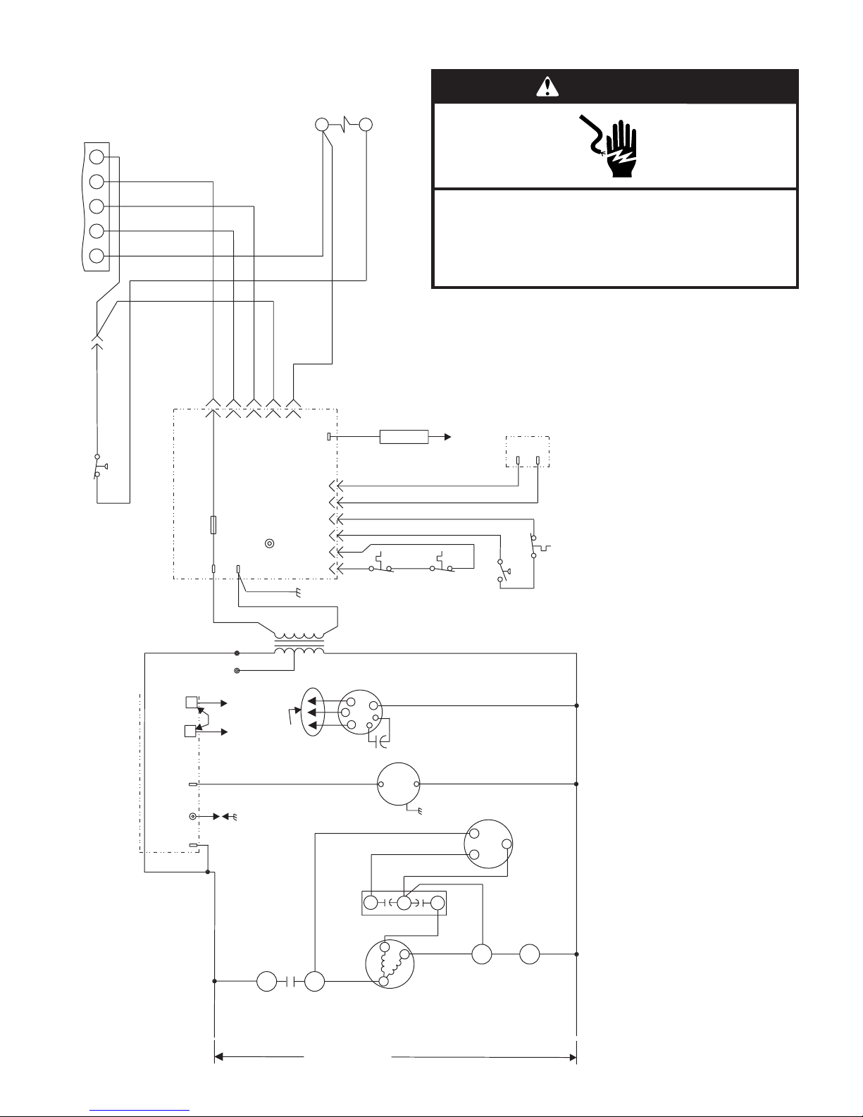
Wiring Connection Diagram—Single Phase, Multi-Speed
Contactor
WARNING
S1
Thermostat
YGW1 RC
BU
Y
Switch
(If used)
High Pressure
S4
K1
Y
Y
Y
R
W
G
Y
Disconnect power before servicing.
Replace all parts and panels before operating.
Electrical Shock Hazard
Failure to do so can result in death or electrical shock.
BU
Y
Ignition Control
A3
BK
R
24VAC
R
G
Fuse
W
Ground
G
240V
208V
C
LED
Y
Flame
3
4
625
1
BU
24V
Transformer
R
OR
T1
GY
BU
PR
PR
BR
Main
Flame
Sense
S10
Limit
Switch
GV1
S47
ollout
Switch
R
OR
W
S18
Pressure
W
Switch
S21
PR
Gas
Aux. Limit
Valve
Switch
(If used)
ACB
Heat
ACB
Cool
CMB BLWR
A3
L1
Ignition Control
BU
Jumper (installed
on some models)
BK
BK
E1
Spark
BK
L1
See Blower
K1-1
Compressor
L1
16
For Wiring
Speed Chart
BK
Contactor
T1
208/230V
B3
Dual
BK
Indoor
L
C
M
H
C4
B6
BR
F
Capacitor
C12
C
-1-60
Blower
Capacitor
Air
Comb.
PR
S
B1
Motor
Blower
C
Y
R
R
Compressor
W
BK
P/N 48129-001
B4
Wiring Connection Diagram
Fan Motor
Condenser
H
R
T2
L2
K1-2
Contactor
Compressor
L2
Single Stage Heat, Single Phase
Page 17
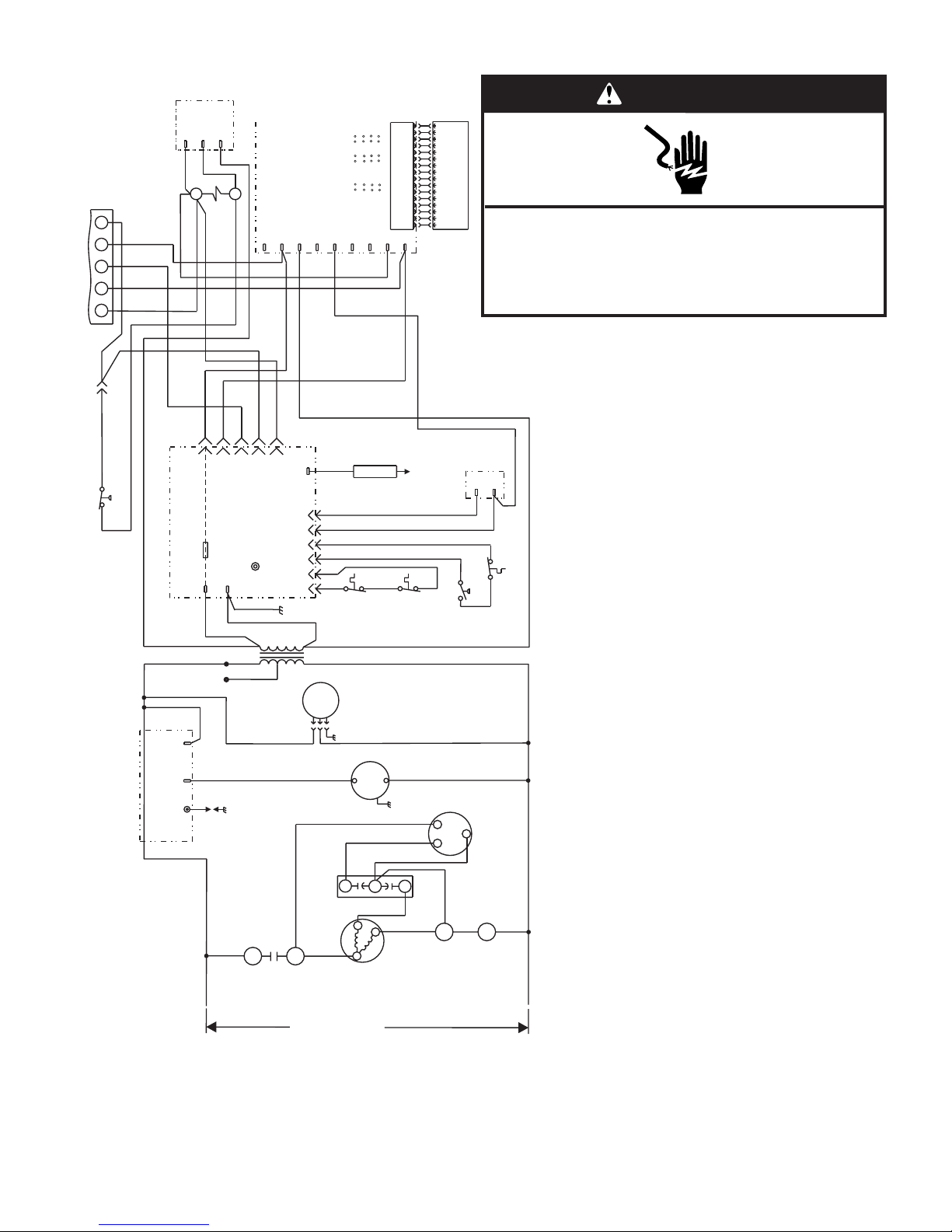
Wiring Connection Diagram—Single Phase, Variable-Speed
S1
C
R
W1
G
Thermostat
Y
BU
Y
Switch
(If used)
High Pressure
S4
Comfort
Alert
A132
Contactor
R
W
G
R
C
Y
R
BU
Y
K1
Y
A54
See
ICM Board
Y
HUM
R
C1
A
A
HEAT COOL
Chart
Blower Speed
EM
W1
ADJUST
NORM
O
Y
G
(+)
Y
R
BU
BU
16
16
15
15
14
13
D
B
C
12
11
B
10
D
C
9
8
7
6
5
(-)
4
(TEST)
3
2
1
G
Y2
Y1
B3
14
13
12
11
10
9
8
7
Motor
6
5
4
Indoor Blower
3
2
1
Disconnect power before servicing.
Replace all parts and panels before operating.
Failure to do so can result in death or electrical shock.
G
WARNING
Electrical Shock Hazard
OR
Y
R
G
Y
C
W
Flame
3
4
Ignition Control
A3
24VAC
R
R
BK
Fuse
Ground
G
BU
240V
208V
LED
625
1
24V
B3
Flame
Sense
GY
Gas
Valve
GV1
BU
R
PR
PR
OR
S10
S47
OR
Main
Limit
W
Switch
BU
WT
Switch
Rollout
BR
T1
S18
Pressure
Switch
S21
(If used)
PR
Aux. Limit Switch
BK
L1
CMB
BLWR
Ignition Control
A3
Spark
L1
E1
BK
BK
K1-1
Compressor
Contactor
L1
543
Transformer
BK
Dual
Capacitor
BK
T1
208/230V-1-60
Indoor
B6
BR
F
C12
Blower
Air
Comb.
PR
S
C
Motor
Blower
C
Y
R
R
B1
Compressor
W
BK
B4
Fan Motor
Condenser
H
R
T2
L2
K1-2
Contactor
Compressor
L2
DIAGNOSTICS
The following ignition control board LED codes will
indicate normal or abnormal operations:
SLOW FLASH Normal operation, no call for heat.
FAST FLASH Normal operation, call for heat.
2 FLASHES System lockout.
3 FLASHES Pressure switch senses incorrect pressure..
4 FLASHES Main limit open or rollout switch open.
5 FLASHES Flame sensed and gas valve not energized.
STEADY Internal failure (micro-controller failure; self check).
P/N 48107-001
Wiring Connection Diagram
Single Stage Heat, Variable Speed, Single Phase
17
Page 18
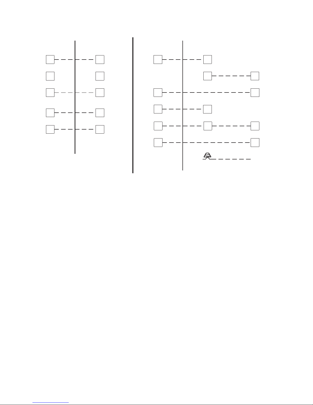
Typical Low Voltage Connections
WITHOUT ECONOMIZER
THERMOSTAT
OUTDOOR UNIT
RR
CC
YY
W
G
W
G
THERMOSTAT
Y1
W
G G
Y2
WITH ECONOMIZER
OUTDOOR UNIT
RR
C
W
BU
Y
G
BK
OR
ECONOMIZER
C
Y1
G
Y2
(Not Used)
18
Page 19
ASSISTANCE OR SERVICE
If you need further assistance, you can write to the below
address with any questions or concerns:
Whirlpool® Home Cooling and Heating
14610 Breakers Drive
Jacksonville, FL 32258
Please include a daytime phone number in your correspondence.
Accessories
To order accessories ask for the appropriate part number listed
below or contact your Whirlpool
dealer.
Part
Number Accessory Model(s)
48193-004 ALPKT804-1
LP Conversion Kit
®
Home Cooling and Heating
W2PG324A068
through
W2PG336A090
48193-005 ALPKT805-1
LP Conversion Kit
48193-001 ALIFT801-1
Lifting Bracket Kit
W2PG342A083
through
W2PG360B110
All
19
Page 20

48289K005
© 2005. All rights reserved.
Manufactured under license by Tradewinds Distributing Company, LLC., Coconut Grove, Florida
Honeywell and SmartValve are trademarks of Honeywell International, Inc.
®Registered Trademark/TM Trademark of Whirlpool, U.S.A.,
Printed in U.S.A.
11/05
 Loading...