

Whirlpool W2PH3, W2PC3, W4PH4, W4PC4 Installation Instructions Manual
INSTALLATION INSTRUCTIONS FOR
PACKAGE HEAT PUMP OR PACKAGE COOLING UNIT
Table of Contents
HEAT PUMP/ELECTRIC COOLING SAFETY...............................1
INSTALLATION REQUIREMENTS................................................2
Tools and Parts ............................................................................2
Location Requirements................................................................2
Ductwork Requirements ..............................................................2
Electrical Requirements ...............................................................3
INSTALLATION INSTRUCTIONS..................................................3
Inspect Shipment.........................................................................3
Place Heat Pump or Condensing Unit in Final Location .............3
Convert to Downflow ...................................................................4
Connect Condensate Drain .........................................................4
Install Ductwork............................................................................5
Install Accessory Heater ..............................................................5
Make Electrical Connections .......................................................6
HEAT PUMP/ELECTRIC COOLING SAFETY
Complete Installation....................................................................7
SEQUENCE OF OPERATION ........................................................7
Cooling Cycle—Cooling Only ......................................................7
Cooling Cycle—Heat Pump Only.................................................7
Heating Cycle ...............................................................................8
Defrost Cycle................................................................................8
Adjust Defrost System .................................................................9
Troubleshoot the Defrost System................................................9
Circulating Air Blower (PSC Motor)............................................10
Circulating Air Blower (Variable Speed Motor) ..........................10
SYSTEM MAINTENANCE ............................................................11
TROUBLESHOOTING ..................................................................12
ASSISTANCE OR SERVICE.........................................................16
Accessories ................................................................................16
Your safety and the safety of others are very important.
We have provided many important safety messages in this manual and on your appliance. Always read and obey all safety
messages.
This is the safety alert symbol.
This symbol alerts you to potential hazards that can kill or hurt you and others.
All safety messages will follow the safety alert symbol and either the word “DANGER” or “WARNING.”
These words mean:
You can be killed or seriously injured if you don't immediately
DANGER
WARNING
All safety messages will tell you what the potential hazard is, tell you how to reduce the chance of injury, and tell you what can
happen if the instructions are not followed.
follow instructions.
can be killed or seriously injured if you don't
You
instructions.
Whirlpool® Models
W2PH3, W2PC3,
W4PH4, W4PC4
48373F007
Whirlpool® Home Cooling and Heating
14610 Breakers Drive
Jacksonville, FL 32258
follow
INSTALLATION REQUIREMENTS
These instructions are intended as a general guide only for use by
qualified persons and do not supersede any national or local
codes in any way. Compliance with all local, state, or national
codes pertaining to this type of equipment should be determined
prior to installation.
Read this entire instruction manual, as well as the instructions
supplied in separate equipment, before starting the installation.
The installation of the heat pump or condensing unit, wiring,
warm air ducts, venting, etc., must conform to the requirements
of the National Fire Protection Association; the National Electrical
Code, ANSI/NFPA No. 70 (latest edition) in the United States, and
any state laws, local ordinances (including plumbing or
wastewater codes). Local authorities having jurisdiction should
be consulted before installation is made. Such applicable
regulations or requirements take precedence over the general
instructions in this manual.
Tools and Parts
Gather the required tools before starting installation. Read and
follow the instructions provided with any tools listed here.
Tools needed
■ ⁵⁄₁₆" nut driver
■ Screwdriver
■ Tape m e a sure
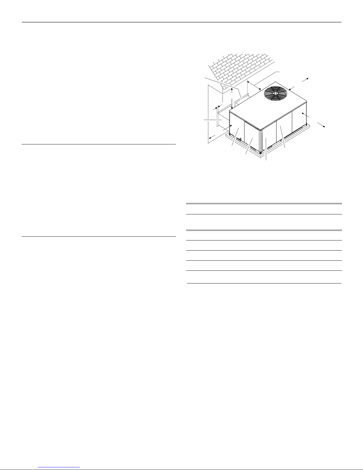
Minimum Clearances
F
36"
2"
E
30"
D
C
A. Heater compartment access panel
B. Blower access panel
C. Evaporator coil access panel
Minimum - 3"
Recommended - 24"
24"
48"
Front side of unit
A
B
D. Filter access panel
E. Return air duct
F. Supply a i r duct
Parts needed
Check local codes and existing electrical supply. Read “Electrical
Requirements” and “Ductwork Requirements” before purchasing
parts.
Location Requirements
■ This heat pump or condensing unit is designed to be located
outdoors with sufficient clearance for free entrance to the
inlet and discharge air openings. The location must also allow
for adequate service access. See “Minimum Clearances.”
■ Where possible, select a location for the heat pump or
condensing unit which is shaded from the direct rays of the
sun most of the time. North or east locations are usually most
desirable. Position the heat pump or condensing unit to avoid
direct contact with water, snow or ice from a roofline
overhead.
■ The heat pump or condensing unit must be installed on a
solid, level mounting pad that will not settle or shift. Isolate
the pad from the building structure to avoid possible
transmission of sound or vibration from the heat pump or
condensing unit into the conditioned space.
■ The heat pump or condensing unit foundation should be
raised to a minimum of 3" above finish grade. In areas which
have prolonged periods of temperature below freezing and
snowfall, the heat pump or condensing unit should be
elevated above the average snow line. If the heat pump or
condensing unit is to be installed on a flat roof, it should be
on a platform or other support which will raise the base a
minimum of 8" above the surface of the flat roof.
■ Avoid placing a heat pump or condensing unit near areas
such as sleeping quarters or study rooms. Normal operating
sound levels may be louder than desired if the heat pump or
condensing unit is placed near certain rooms.
Minimum Clearance Requirements
For Optimum
Service Access
Front 48" 24"
Rear 24" 3"
Condenser End 24" 3"
Blower End 30" 0"
Top 36" 36"
For Optimum
Operation
Ductwork Requirements
■ Install all conditioned air plenums, ducts and air filters in
accordance with NFPA 90B Standard for the Installation of
Warm Air Heating and Air-Conditioning Systems (latest
edition).
■ The heat pump or condensing unit is provided with flanges
for the connection of the plenum and ducts.
■ All air filters must be listed as Class 2 air filters.
■ All ductwork must be made of materials and insulated to
meet local, state and national codes. Ductwork installed
outdoors must be sealed, weatherproof and protected
against physical damage. Caulking, flashing or other means
of adequately providing a permanent weather seal should be
used where duct penetrates a building or structure opening.
2
Electrical Requirements
WARNING
Electrical Shock Hazard
Electrically ground condensing unit or heat pump.
Connect ground wire to ground terminal
marked “GROUND”.
Use copper wire for supply connection.
Correct wire gauge is shown in the chart below.
Failure to follow these instructions can result in
death or electrical shock.
■ All field wiring must be done in accordance with National
Electrical Code requirements, applicable requirements of UL,
or local codes, where applicable.
■ Electrical wiring, disconnect means and over current
protection are to be supplied by the installer. Refer to the
rating plate for the maximum over current protection,
minimum service ampacity, and operating voltage. See the
wiring connection diagrams in “Troubleshooting.”
■ This heat pump or condensing unit must be electrically
grounded in accordance with National Electric Code (ANSI/
NFPA 70) requirements, applicable requirements of UL, or
local codes, where applicable.
Rating Plate Ampacity
Less than 15
16 - 20
21 - 30
31 - 50 8
NOTE: All outdoor wiring must be suitable for outdoor use. Use
copper conductors only.
AWG
14
12
10
INSTALLATION INSTRUCTIONS
Inspect Shipment
WARNING
Excessive Weight Hazard
Use two or more people and mechanical equipment to
lift, move and install condensing unit or heat pump.
Failure to do so can result in back or other injury.
This heat pump or condensing unit is shipped in one package,
completely assembled and wired. The indoor thermostat and
accessories are shipped in a separate carton when ordered.
1. Check the heat pump or condensing unit rating plate to
confirm specifications are as ordered.
2. Upon receipt of heat pump or condensing unit, inspect it for
possible shipping damage. Be sure to examine the heat
pump or condensing unit inside the carton if the carton is
damaged.
If damage is found, it should be noted on the carrier’s freight bill.
Damage claims should be filed with the carrier immediately.
Claims of shortages should be filed with the seller within 5 days.
NOTE: If any damages are discovered and reported to the carrier,
do not install the heat pump or condensing unit as your claim
may be denied.
Place Heat Pump or Condensing Unit in
Final Location
WARNING
Excessive Weight Hazard
Use two or more people and mechanical equipment to
lift, move and install condensing unit or heat pump.
Failure to do so can result in back or other injury.
IMPORTANT: Place the heat pump or condensing unit in the final
location and position it in the proper orientation to the house so
that connecting ducts and electrical supplies is easily done.
Hoisting may be required.
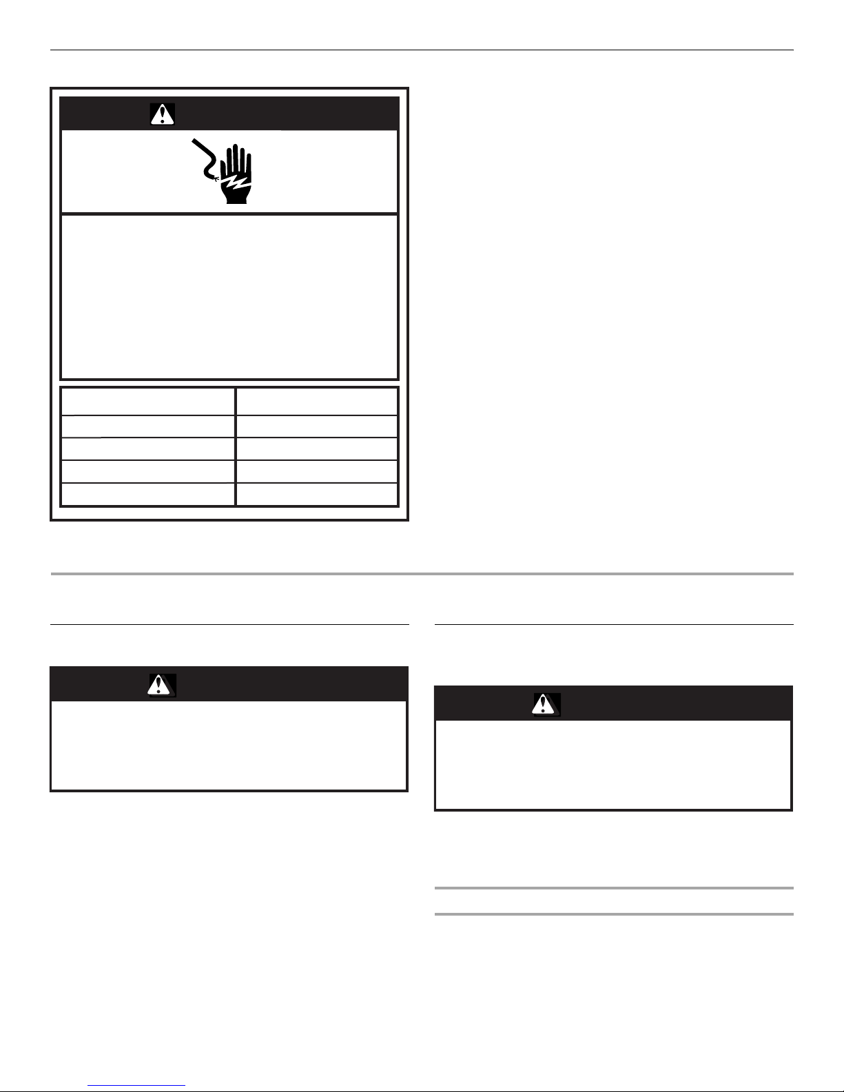
Hoisting
An accessory lift kit must be purchased to hoist the heat pump or
condensing unit. See “Accessories.” Attach the rigging to the
lifting brackets on each corner.
NOTE: All access panels must be secured in place before
hoisting.
3
The heat pump or condensing unit should be hoisted with 2 lifting
slings. Attach the slings to rigging shackles that have been
hooked through holes in the lifting brackets.
Place 2 spreaders on top of the heat pump or condensing unit to
protect it from damage from the pressure exerted by the slings.
Make sure that all equipment is rated to handle at least 750 lbs
and that the slings will not allow the heat pump or condensing
unit to shift. See “Typical Sling Configuration.”
Typical Sling Configuration
A
A. Spreaders
B. Cables
C. Lifting bracket (accessory lift kit)
B
C
D
E
D. Sheet metal
screw
E. Pallet
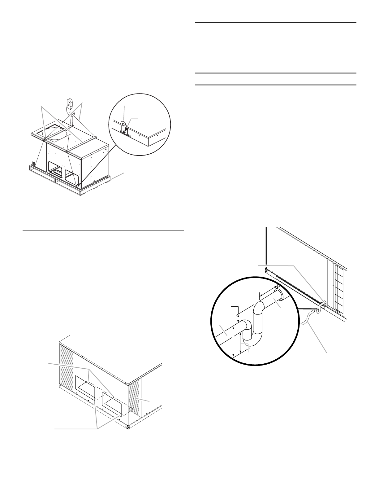
Connect Condensate Drain
The condensate drain outlet is a ³⁄₄" threaded PVC fitting located
at the bottom on the side of the heat pump or condensing unit. A
³⁄₄" drain line with trap must be installed on all applications to
avoid accumulation of condensate under or around the heat
pump or condensing unit.
Install Condensate Trap
1. Construct the condensate trap from PVC tubing as shown in
“Condensate Trap Construction.”
NOTES:
■ The condensate trap allows a standing column of water of
at least 2" (50 mm).
■ The top of the drain trap inlet must be at least least 1"
(25 mm) above the top of the drain trap outlet.
■ The trap should be installed as close to the heat pump or
condensing unit as possible, while still providing proper
drainage.
■ For service access, do not block heat exchanger access
panel or the filter access panel with the drain line.
2. Thread the drain assembly into the ³⁄₄" PVC fitting.
NOTE: Do not glue the threaded fitting so it can be removed
during servicing of unit.
3. Run the drain line to an open drain or other suitable disposal
point.
Condensate Trap Construction
Convert to Downflow
This heat pump or condensing unit is factory-built for horizontal
airflow applications and may also be field-converted for
downflow use.
To convert to downflow use:
1. Remove the filter access panel.
2. Remove the two downflow duct cover plates (one screw and
tab for each) found in the return and supply air
compartments.
3. Using eight #10 x ³⁄₄" screws (field supplied), install the
previously removed duct covers on the horizontal return and
supply air openings. Use the pilot holes provided.
4. Reinstall the filter access panel.
A
B
A
12" Max.
1" Min.
D
3" Min.
2" Min.
A.
³⁄₄
" PVC fitting (threaded) drain
condensate connection
³⁄₄
" drain pipes, field provided
B.
C
B
C. Drain trap outlet
D. Drain trap inlet
C
A. Horizontal return and supply air openings
B. Filter access panel
C. Downflow duct cover plates
4
Install Ductwork
D
A
■ Install ductwork in accordance with NFPA 90B and any local
codes.
■ The use of flexible, noncombustible connectors between the
main trunk ducts and the supply and return air plenums is
recommended to minimize vibration transmission.
■ Plenums must be individually sealed to heat pump or
condensing unit casing with ducts terminating inside the
structure.
■ Flashing used to cover ductwork must permit removal of
access panels and top. See “Minimum Clearances” in the
“Locations Requirements” section.
Filters
Filters are not supplied with these heat pumps or condensing
units; however, filters must be used. It is the installer’s
responsibility to install a filter rack with the ductwork and to
install properly sized filters in accordance with the Minimum
Required Surface Area for Disposable Filters chart.
Install Accessory Heater
WARNING
All return air must pass through a filter before entering the heat
pump or condensing unit. An electronic air cleaner, filter rack or
other accessible filter arrangement must be installed in the return
air ductwork. Minimum recommended filter areas are listed in the
Minimum Required Surface Area for Disposable Filters chart, and
are based on a face velocity of 325 ft (99.1 m) per min. for
disposable filters and 525 ft (160 m) per min. for cleanable filters.
Minimum Required Surface Area for Disposable Filters
Nominal Cooling Filter Area (sq. ft)
24,000 2.67
30,000 3.33
36,000 4.00
42,000 4.67
48,000 5.33
60,000 6.67
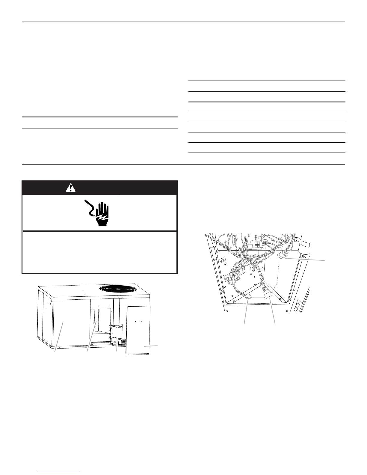
3. Remove the heater blockoff by removing the 4 screws
holding it in place.
4. Insert the heater kit into the control panel and fasten in the
same mounting holes.
5. Disconnect the plugs connecting the no-heat wire harness to
the control assembly wire harness.
6. Remove the no-heat wire harness plugs.
Electrical Shock Hazard
Disconnect power before servicing.
Replace all parts and panels before operating.
Failure to do so can result in death or electrical shock.
A
A. Blower access panel
B. Heater blockoff
1. Disconnect power.
2. Remove the heater compartment access panel.
BC
C. Heater kit
D. Heater compartment access panel
C
A. No-heat wire harness
B. Control assembly wire harness
C. Heater wire harness
7. Plug the heater wiring harness into the control assembly wire
harness.
8. See “Make Electrical Connections” for instructions on
connecting power to the heater kit.
9. Replace the heater compartment access panel.
10. Reconnect power.
B
5
 Loading...