

Whirlpool W2H3, W2H4 Installation Instructions Manual
HEAT PUMP INSTALLATION INSTRUCTIONS
Table of Contents
HEAT PUMP SAFETY.....................................................................1
INSTALLATION REQUIREMENTS................................................ 1
Tools and Parts ............................................................................2
System Requirements..................................................................2
Location Requirements................................................................2
Electrical Requirements ...............................................................3
INSTALLATION INSTRUCTIONS..................................................3
Inspect Shipment.........................................................................3
Connect Refrigerant Lines ...........................................................4
Charge Refrigerant Lines .............................................................5
Make Electrical Connections .......................................................6
HEAT PUMP SAFETY
Your safety and the safety of others are very important.
We have provided many important safety messages in this manual and on your appliance. Always read and obey all safety
messages.
This is the safety alert symbol.
This symbol alerts you to potential hazards that can kill or hurt you and others.
All safety messages will follow the safety alert symbol and either the word “DANGER” or “WARNING.”
These words mean:
Complete Installation....................................................................7
SEQUENCE OF OPERATION ........................................................8
Cooling .........................................................................................8
Heating .........................................................................................8
Defrost Cycle................................................................................8
Adjusting Defrost System.............................................................9
Troubleshoot the Defrost System..............................................10
SYSTEM MAINTENANCE ............................................................10
ASSISTANCE OR SERVICE.........................................................10
Accessories ................................................................................10
WARRANTY ..................................................................................11
You can be killed or seriously injured if you don't immediately
DANGER
WARNING
All safety messages will tell you what the potential hazard is, tell you how to reduce the chance of injury, and tell you what can
happen if the instructions are not followed.
follow instructions.
can be killed or seriously injured if you don't
You
instructions.
INSTALLATION REQUIREMENTS
These instructions are intended as a general guide only for use by
qualified persons and do not supersede any national or local
codes in any way. The installation must comply with all state and
local codes as well as the National Electrical Code.
Whirlpool® Models W2H3 and W2H4
506112-01
■ The heat pump is designed and approved for outdoor use
only.
■ The heat pump must be installed with no ductwork in the
airstream. The outdoor fan is not designed to operate against
any additional static pressure.
follow
Tools and Parts
Gather the required tools and parts before starting installation.
Read and follow the instructions provided with any tools listed
here.
Tools Needed
■ To rc h
■ ¹⁄₄" (6.4 mm) nut driver
■ ⁵⁄₁₆" (7.6 mm) nut driver
System Requirements
Heat pump system matches are derived from actual laboratory
testing of matched systems. It is recommended that only
matching equipment be used to ensure proper operation and
efficient performance.
■ The designed system matches are listed in the heat pump
specification sheets and on the heat pump refrigerant
charging instructions located on the back of the service
access panel.
■ Refrigerant charging instructions include a list of matching
indoor equipment with the proper thermal expansion valve
size and amount of refrigerant charge required.
■ This heat pump has been factory charged with a quantity of
refrigerant (R-22) sufficient for a matched indoor coil and a
maximum 15 ft (4.6 m) of refrigerant line.
Location Requirements
■ This heat pump is designed to be located outdoors with
sufficient clearance for free entrance to the inlet and
discharge air openings. The location must also allow for
adequate service access. See “Minimum Clearances.”
■ Where possible, select a location for the heat pump which is
shaded from the direct rays of the sun most of the time. North
or east locations are usually most desirable. Position the heat
pump to avoid direct contact with water, snow or ice from a
roofline overhead.
■ The heat pump must be installed on a solid, level mounting
pad that will not settle or shift. Isolate the pad from the
building structure to avoid possible transmission of sound or
vibration from the heat pump into the conditioned space.
■ The heat pump foundation should be raised to a minimum of
3" (7.6 cm) above finished grade. In areas which have
prolonged periods of temperatures below freezing, and/or
snowfall, the heat pump should be elevated above the
average snow line. If heat pump is to be installed on a flat
roof, it should be on a platform or other support which will
raise the inlet air opening 12" (30.5 cm) minimum above the
surface of the flat roof.
■ Avoid ice accumulation by ensuring free drainage of
condensate from defrost cycles. The heat pump should be
located away from walkways to avoid possible icing from
defrost condensate.
■ Avoid placing the heat pump near areas such as sleeping
quarters or study rooms. Normal operating sound levels may
be objectionable if the heat pump is placed near certain
rooms. A shift in sound type does occur during the defrost
mode. The defrost mode generally lasts no longer than
10 minutes.
Parts Needed
Check local codes and HVAC supplier. Check existing electrical
supply, and read “Electrical Requirements,” “Location
Requirements,” “System Requirements” and “Connect
Refrigerant Lines.”
Indoor System Thermal Expansion Valve
■ Check the indoor coil thermal expansion valve to see whether
it matches the required thermal expansion valve for the
indoor coil and heat pump combination being installed.
■ Refer to the refrigerant charge label located on the inside of
the heat pump access panel for the correct thermal
expansion valve size required.
■ Replace the thermal expansion valve with the correct size if
this size is not already installed in the indoor coil. Instructions
for replacing the thermal expansion valve are provided with
the indoor coil.
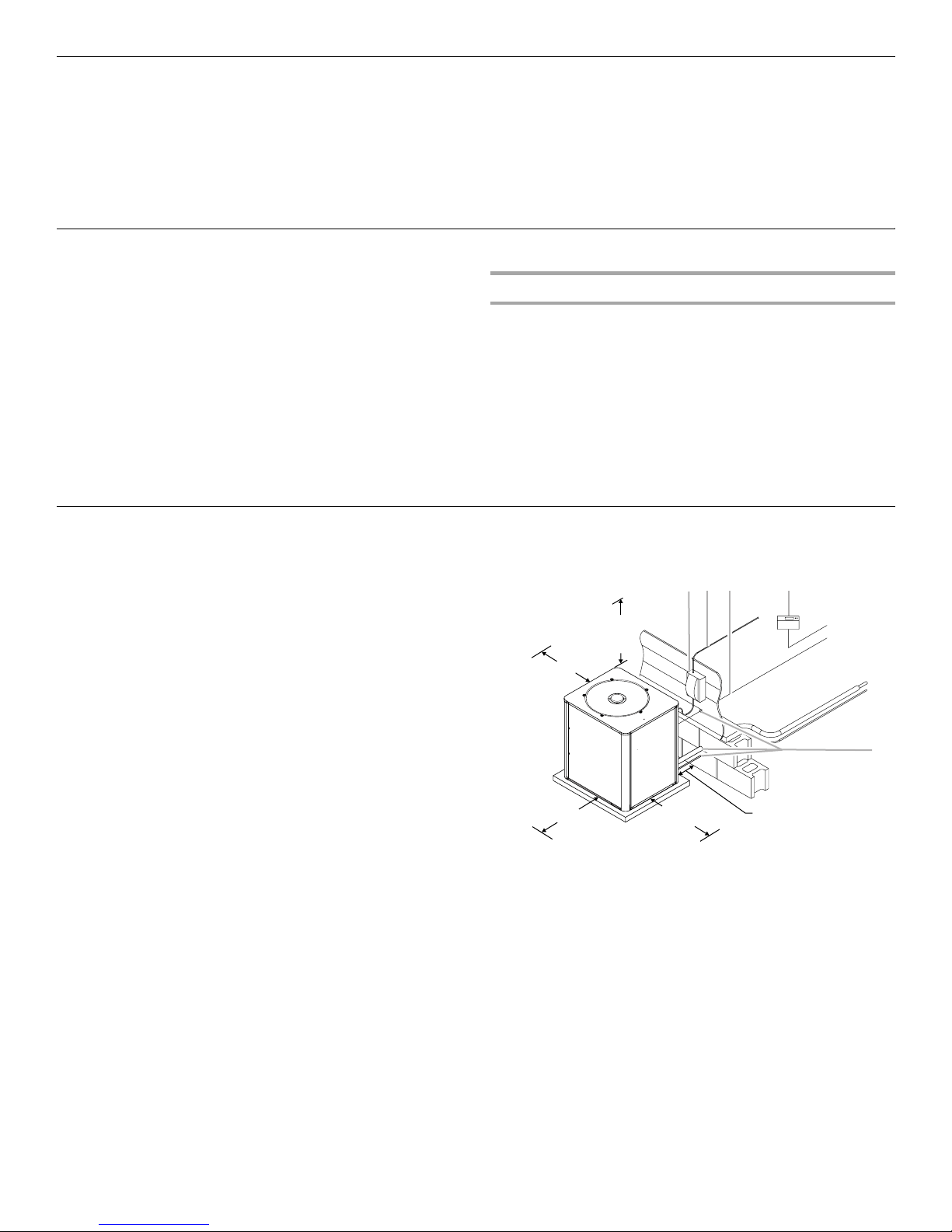
Minimum Clearances
AB C E
48" (121.9 cm)
Overhead Clearance
(Discharge Air)
12" (30.5 cm)
Clearance (Inlet Air)
Clearance (Inlet Air)
36" (91.4 cm)
30" (76.2 cm) Service
Access Clearance
A. Weatherproof disconnect switch
B. NEC class 1 wiring
C. NEC class 2 wiring
D. To power supply
D
12" (30.5 cm) Clearance
Between Unit and Building
E. House thermostat
F. To indoor unit
G. To indoor coil
H. Seal openings
F
G
H
2
Electrical Requirements
WARNING
Electrical Shock Hazard
Electrically ground condensing unit or heat pump.
Connect ground wire to ground lug.
Use copper wire for supply connection.
Correct wire gauge is shown in the chart below.
Failure to follow these instructions can result in
death or electrical shock.
■ All field wiring must be done in accordance with National
Electrical Code requirements, applicable requirements of UL,
or local codes, where applicable.
■ Electrical wiring, disconnect means and over-current
protection are to be supplied by the installer. Refer to the
rating plate for the maximum over-current protection,
minimum circuit ampacity, and operating voltage. See the
wiring diagrams in “Make Electrical Connections.”
Rating Plate Ampacity
Less than 15
16 - 20
21 - 30
31 - 50
NOTE: All outdoor wiring must be suitable for outdoor use. Use
copper conductors only.
AWG
14
12
10
8
INSTALLATION INSTRUCTIONS
Inspect Shipment
WARNING
Excessive Weight Hazard
Use two or more people to move and install
condensing unit or heat pump.
Failure to do so can result in back or other injury.
This heat pump is shipped in one package, completely
assembled and wired. The thermostat is shipped in a separate
carton when ordered.
1. Check the heat pump rating plate to confirm specifications
are as ordered.
2. Upon receipt of heat pump, inspect it for possible shipping
damage. Examine the heat pump inside the carton if the
carton is damaged.
If damage is found, it should be noted on the carrier’s freight bill.
Damage claims should be filed with the carrier immediately.
Claims of shortages should be filed with the seller within 5 days.
NOTE: If any damages are discovered and reported to the carrier,
do not install the heat pump because your claim may be denied.
3

Connect Refrigerant Lines
Refrigerant lines must be connected by a licensed, EPA certified
refrigerant technician in accordance with established procedures.
IMPORTANT:
■ Connecting refrigerant lines must be clean, dehydrated,
refrigerant-grade copper lines. Heat pumps should be
installed only with specified line sizes for approved system
combinations with elevation differences up to 15 ft (4.6 m)
and total length of up to 50 ft (15.2 m). See the Suction Line
Sizes and Liquid Line Sizes charts.
■ Sharp bends or possible kinking in the lines will cause a
reduction in performance.
■ To avoid contamination of the refrigerant system, do not
remove the caps from the lines or system connection points
until connections are ready to be completed.
1. Route the suction and liquid lines from the fittings on the
indoor coil to the fittings on the heat pump. Run the lines in
as direct a path as possible, avoiding unnecessary turns and
bends.
2. For product efficiency, be sure that the suction line is
insulated over the entire exposed length and that both
suction and liquid lines are not in direct contact with floors,
walls, ductwork, floor joists, or other piping.
3. Remove valve cores.
4. Wrap the service valves with a wet rag.
5. Connect the suction and liquid lines, using a brazing
compound. Braze with an alloy of silver or copper and
phosphorus with a melting point above 1,100°F (593ºC).
NOTE: Do not use soft solder.
6. Make sure indoor coil has been put in place according to the
Installation Instructions and is connected to the refrigerant
lines.
7. Replace valve cores.
8. Pressurize the lines and indoor coil with a pressure not to
exceed 20 psi.
9. Leak test the lines with a pressure not to exceed 20 psig.
10. Evacuate the indoor coil and lines to a minimum of
500 microns to remove contamination and moisture, then
disconnect the vacuum pump.
11. Open the suction and liquid service valves fully.
12. Insulate the suction line with refrigerant line insulation
material of ¹⁄₄" (6.4 mm) or more wall thickness.
13. Pack insulating material around refrigerant lines where they
penetrate the structure to protect the lines and to minimize
vibration transmission.
A
A. Insulating material around refrigerant lines
Suction Line Sizes
Installations exceeding 100 ft (30.5 m) are not recommended.
Btu/h Line Set Size—in. (cm) OD
18,000 ³⁄₄ (1.9) ³⁄₄ (1.9) ³⁄₄ (1.9)
24,000 ³⁄₄ (1.9) ³⁄₄ (1.9) ³⁄₄ (1.9)
30,000 ³⁄₄ (1.9) ³⁄₄ (1.9) ³⁄₄ (1.9)
36,000 ⁷⁄₈ (2.2) ⁷⁄₈ (2.2) ⁷⁄₈ (2.2)
42,000 ⁷⁄₈ (2.2) ⁷⁄₈ (2.2) ⁷⁄₈ (2.2)
48,000 ⁷⁄₈ (2.2) ⁷⁄₈ (2.2) ⁷⁄₈ (2.2)
60,000 1¹⁄₈ (2.9) 1¹⁄₈ (2.9) 1¹⁄₈ (2.9)
Line Set
Length
Less than 25 ft
(7.6 m)
25 ft
(7.6 m)
Over 25 ft (7.6 m) and up
to 50 ft (15.2 m)
Liquid Line Sizes
Installations exceeding 100 ft (30.5 m) are not recommended.
Btu/h Line Set Size—in. (cm) OD
18,000 ³⁄₈ (1) ³⁄₈ (1) ³⁄₈ (1)
24,000 ³⁄₈ (1) ³⁄₈ (1) ³⁄₈ (1)
30,000 ³⁄₈ (1) ³⁄₈ (1) ³⁄₈ (1)
36,000 ³⁄₈ (1) ³⁄₈ (1) ³⁄₈ (1)
42,000 ³⁄₈ (1) ³⁄₈ (1) ³⁄₈ (1)
48,000 ³⁄₈ (1) ³⁄₈ (1) ³⁄₈ (1)
4
60,000 ³⁄₈ (1) ³⁄₈ (1) ³⁄₈ (1)
Line Set
Length
Less than 25 ft
(7.6 m)
25 ft
(7.6 m)
Over 25 ft (7.6 m) and up
to 50 ft (15.2 m)
 Loading...