

Page 1
CONDENSING UNIT INSTALLATION INSTRUCTIONS
Table of Contents
CONDENSING UNIT SAFETY........................................................1
INSTALLATION REQUIREMENTS................................................2
Tools and Parts ............................................................................2
System Requirements..................................................................2
Location Requirements................................................................2
Electrical Requirements ...............................................................3
INSTALLATION INSTRUCTIONS..................................................3
Inspect Shipment.........................................................................3
CONDENSING UNIT SAFETY
Your safety and the safety of others are very important.
We have provided many important safety messages in this manual and on your appliance. Always read and obey all safety
messages.
This is the safety alert symbol.
This symbol alerts you to potential hazards that can kill or hurt you and others.
All safety messages will follow the safety alert symbol and either the word “DANGER” or “WARNING.”
These words mean:
Connect Refrigerant Lines ...........................................................3
Make Electrical Connections .......................................................5
Complete Installation....................................................................9
SEQUENCE OF OPERATION ........................................................9
SYSTEM MAINTENANCE ..............................................................9
ASSISTANCE OR SERVICE...........................................................9
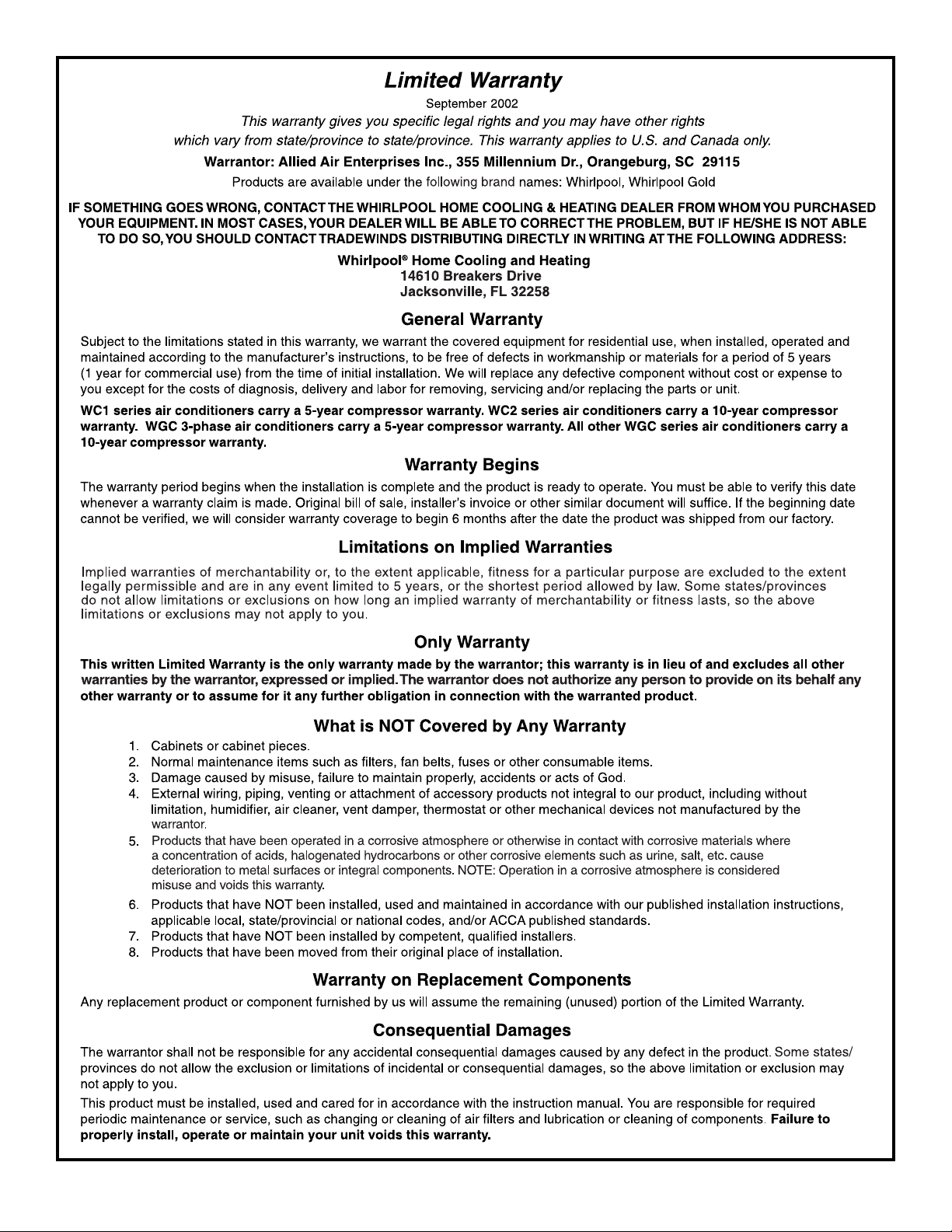
WARRANTY ..................................................................................11
You can be killed or seriously injured if you don't immediately
DANGER
WARNING
All safety messages will tell you what the potential hazard is, tell you how to reduce the chance of injury, and tell you what can
happen if the instructions are not followed.
Whirlpool® Model W2C3
100402-03
follow instructions.
can be killed or seriously injured if you don't
You
instructions.
follow
Page 2
INSTALLATION REQUIREMENTS
These instructions are intended as a general guide only and do
not supersede any national or local codes in any way. The
installation must comply with all state, and local codes as well as
the National Electrical Code.
■ The condensing unit is designed and approved for outdoor
use only.
■ The condensing unit must be installed with no ductwork in
the airstream. The outdoor fan is not designed to operate
against any additional static pressure.
Tools and Parts
Gather the required tools and parts before starting installation.
Read and follow the instructions provided with any tools listed
here.
Tools Needed
■ To rc h
■ ¹⁄₄" nut driver
Parts Needed
Check local codes and HVAC supplier. Check existing electrical
supply, and read “Electrical Requirements,” “Location
Requirements,” “System Requirements” and “Connect
Refrigerant Lines.”
NOTE: Some condensing units do not contain a factory-installed
filter dryer. With those units, a properly sized filter dryer must be
field installed in the liquid (high pressure) line set between the
outdoor condensing unit and indoor evaporator unit.
System Requirements
Condensing unit system matches are derived from actual
laboratory testing of matched systems. It is recommended that
only matching equipment be used to ensure proper operation
and efficient performance.
■ The designed system matches are listed in the condensing
unit specification sheets and on the condensing unit
refrigerant charging instructions located on the back of the
service access panel.
■ Refrigerant charging instructions include a list of matching
indoor equipment with the proper expansion device size and
amount of refrigerant charge required.
■ This condensing unit has been factory charged with a
quantity of refrigerant (R22) sufficient for a matched indoor
coil and a maximum 20 ft of refrigerant line.
■ ⁵⁄₁₆" nut driver
Indoor System Expansion Device
■ Check the indoor coil expansion device to see whether it
matches the required expansion device for the indoor coil
and condensing unit being installed.
■ Refer to the refrigerant charge label located on the inside of
the condensing unit access panel for the correct expansion
device size required.
■ Replace the expansion device with the correct size if this size
is not already installed in the indoor coil. Instructions for
replacing the expansion device are provided with the indoor
coil.
Location Requirements
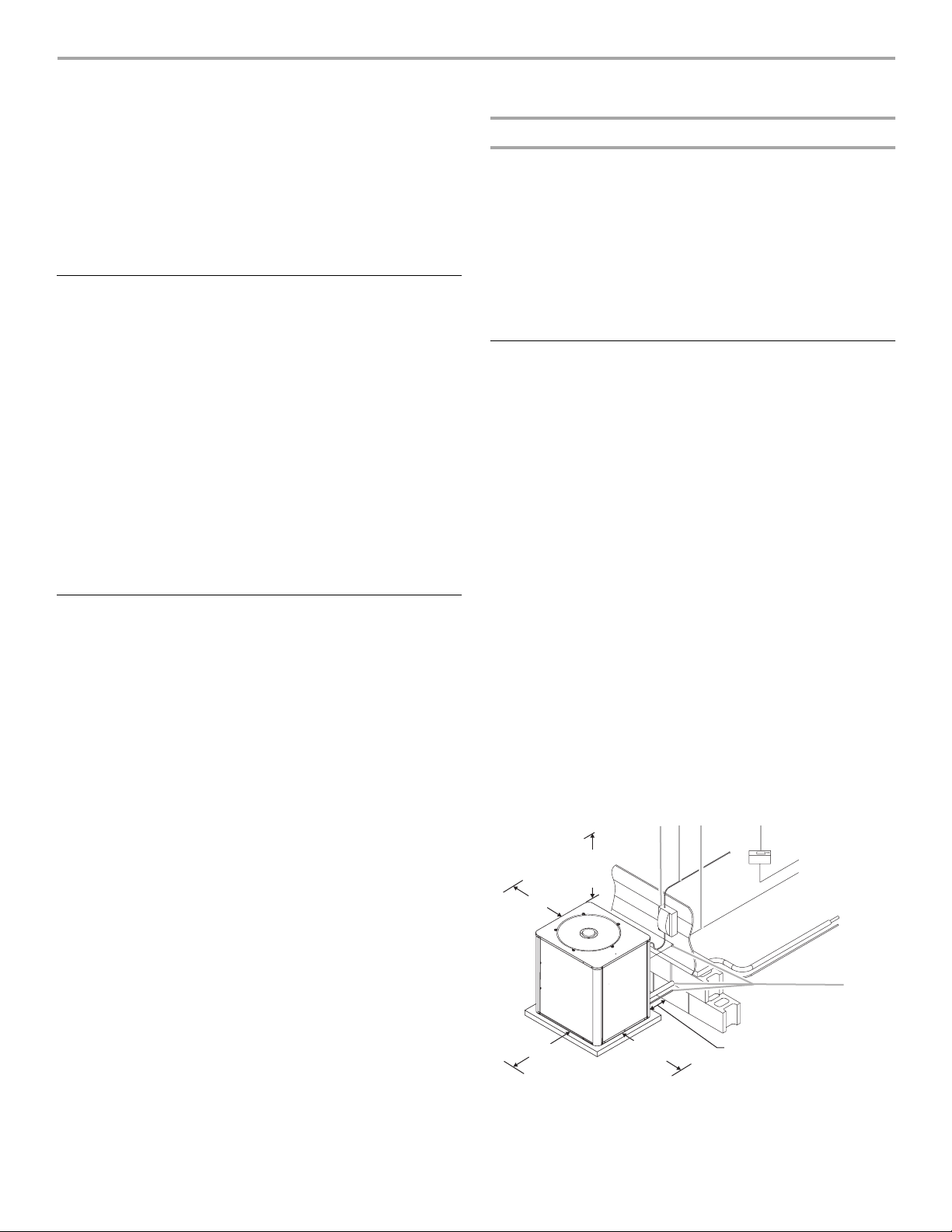
■ This condensing unit is designed to be located outdoors with
sufficient clearance for free entrance to the inlet and
discharge air openings. The location must also allow for
adequate service access. See “Minimum Clearances.”
■ Where possible, select a location for the condensing unit
which is shaded from the direct rays of the sun most of the
time. North or east locations are usually most desirable.
Position the condensing unit to avoid direct contact with
water, snow or ice from a roofline overhead.
■ The condensing unit must be installed on a solid, level
mounting pad that will not settle or shift. Isolate the pad from
the building structure to avoid possible transmission of sound
or vibration from the condensing unit into the conditioned
space.
■ The condensing unit foundation should be raised to a
minimum of 3" above finish grade. In areas which have
prolonged periods of temperatures below freezing, and/or
snowfall, the condensing unit should be elevated above the
average snow line.
■ Avoid placing the condensing unit near areas such as
sleeping quarters or study rooms. Normal operating sound
levels may be objectionable if the condensing unit is placed
near certain rooms.
Minimum Clearances
48" Overhead
Clearance
(Discharge
12" Clearance
(Inlet Air)
AB C D
Air)
To
Power
Supply
To
Indoor
Unit
To
Indoor
Coil
E
12" Clearance
(Inlet Air)
A. Weatherproof disconnect switch
B. NEC class 1 wiring
C. NEC class 2 wiring
24" Service
Access Clearance
12" Clearance Between
Unit and Building
D. House thermostat
E. Seal openings
2
Page 3
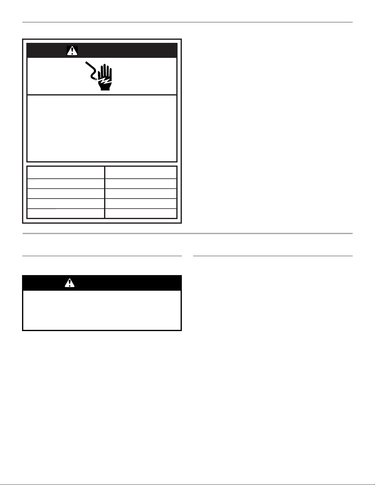
Electrical Requirements
WARNING
Electrical Shock Hazard
Electrically ground condensing unit or heat pump.
Connect ground wire to ground lug.
Use copper wire for supply connection.
Correct wire gauge is shown in the chart below.
Failure to follow these instructions can result in
death or electrical shock.
NOTE: All outdoor wiring must be suitable for outdoor use. Use
copper conductors only.
■ All field wiring must be done in accordance with National
Electrical Code requirements, applicable requirements of UL,
or local codes, where applicable.
■ Electrical wiring, disconnect means and over-current
protection are to be supplied by the installer. Refer to the
rating plate for the maximum over-current protection,
minimum circuit ampacity, and operating voltage. See the
wiring diagrams in “Make Electrical Connections.”
Rating Plate Ampacity
Less than 15
16 - 20
21 - 30
31 - 50
AWG
14
12
10
8
INSTALLATION INSTRUCTIONS
Inspect Shipment
WARNING
Excessive Weight Hazard
Use two or more people to move and install
condensing unit or heat pump.
Failure to do so can result in back or other injury.
This condensing unit is shipped in one package, completely
assembled and wired. The thermostat is shipped in a separate
carton when ordered.
1. Check the condensing unit rating plate to confirm
specifications are as ordered.
2. Upon receipt of equipment, inspect it for possible shipping
damage. Examine the unit inside the carton if the carton is
damaged.
If damage is found, it should be noted on the carrier’s freight bill.
Damage claims should be filed with the carrier immediately.
Claims of shortages should be filed with the seller within 5 days.
NOTE: If any damages are discovered and reported to the carrier,
do not install the unit, because your claim may be denied.
Connect Refrigerant Lines
Refrigerant lines must be connected by a licensed, EPA certified
refrigerant technician in accordance with established procedures.
IMPORTANT:
■ Connecting refrigerant lines must be clean, dehydrated,
refrigerant-grade copper lines. Condensing units should be
installed only with specified line sizes for approved system
combinations with elevation differences up to 20 ft and total
length of up to 100 ft. See the Suction Line Sizes and Liquid
Line Sizes charts later in this section.
■ Avoid sharp bends or possible kinking in the refrigerant lines
during installation as this may cause a reduction in
performance.
■ To avoid contamination of the refrigerant system, do not
remove the caps from the lines or system connection points
until connections are ready to be completed.
1. Route the suction and liquid lines from the fittings on the
indoor coil to the fittings on the condensing unit. Run the
lines in as direct a path as possible, avoiding unnecessary
turns and bends.
2. For product efficiency, be sure that the suction line is
insulated over the entire exposed length and that both
suction and liquid lines are not in direct contact with floors,
walls, ductwork, floor joists, or other piping.
3. Remove valve cores.
4. Wrap the service valves with a wet rag.
3
Page 4
5. If not provided, install a filter dryer in the liquid line between
the outdoor condensing unit and the indoor evaporator coil.
6. Connect the suction and liquid lines, using a brazing
compound. Braze with an alloy of silver or copper and
phosphorus with a melting point above 1,100°F.
NOTE: Do not use soft solder.
7. Make sure indoor coil has been put in place according to the
Installation Instructions and is connected to the refrigerant
lines.
8. Replace valve cores.
9. Pressurize the lines and indoor coil with dry nitrogen not to
exceed 20 psi.
10. Leak test the refrigerant lines and indoor coil.
11. Evacuate the indoor coil and lines to a minimum of
500 microns to remove contamination and moisture, then
disconnect the vacuum pump.
12. Open the suction and liquid service valves fully.
13. Insulate the suction line with refrigerant line insulation
material of ¹⁄₄" or more wall thickness.
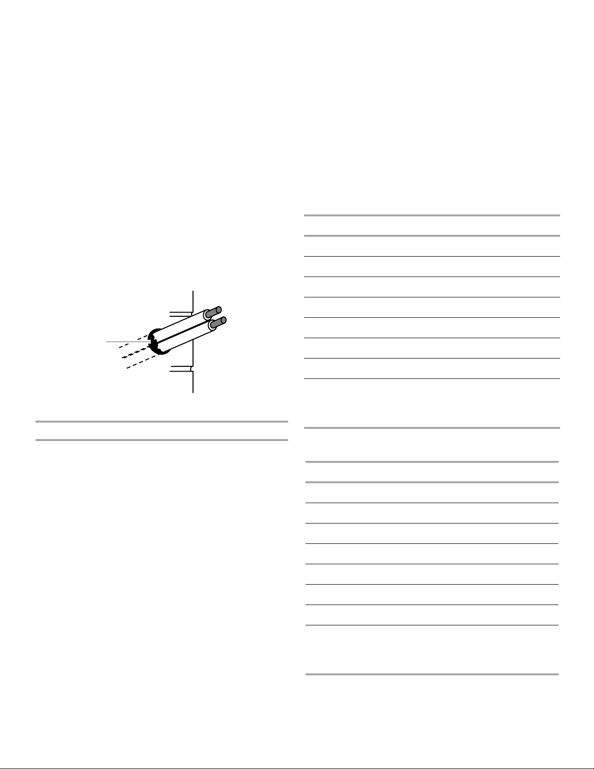
14. Pack insulating material around refrigerant lines where they
penetrate the structure to protect the lines and to minimize
vibration transmission.
■ Adjustment of the refrigerant charge will be necessary based
on the system combination and line length. To adjust the
refrigerant size for increased line lengths, add the following
amount of refrigerant.
For line set lengths greater than 20 ft:
1. Add refrigerant by weighing in 0.60 oz per ft of ³⁄₈" O.D.
liquid line.
2. Add refrigerant by weighing in 1.2 oz per ft of ¹⁄₂" O.D.
liquid line.
■ If necessary, adjust the refrigerant charge for compatibility
with the evaporator coil.
■ In condensing unit systems, horizontal suction lines should
be slightly sloped toward the condensing unit. Piping must
avoid dips or low spots, which can collect oil.
Suction Line Sizes
Installations exceeding 100 ft are not recommended.
BTU/HR Line Set Size (in. OD)
18,000 ³⁄ ₄ ³⁄₄ ³⁄₄ ³⁄₄ ³⁄₄
24,000 ³⁄ ₄ ³⁄₄ ³⁄₄ ³⁄₄ ⁷⁄₈
30,000 ³⁄ ₄ ³⁄₄ ³⁄₄ ⁷⁄₈ ⁷⁄₈
36,000 ³⁄ ₄ ³⁄₄ ³⁄₄ ⁷⁄₈ 1¹⁄₈
A
A. Seal openings where refrigerant lines penetrate structure.
Refrigerant Charge
Refrigerant lines must be connected by a licensed, EPA certified
refrigerant technician in accordance with established procedures.
IMPORTANT:
■ Refrigerant charge adjustment will be required for line set
lengths greater than 20 ft and for non system-matched
evaporator coils.
■ The condensing unit is factory-charged with the proper
refrigerant charge amount for a matching evaporator and
20 ft of refrigerant line. Refer to the condensing unit rating
plate for the exact amount of this factory charge.
42,000 ⁷⁄ ₈ ⁷⁄₈ ⁷⁄₈ 1¹⁄₈ 1¹⁄₈
48,000 ⁷⁄ ₈ ⁷⁄₈ ⁷⁄₈ 1¹⁄₈ 1¹⁄₈
60,000 1¹⁄₈ 1¹⁄₈ 1¹⁄₈ 1¹⁄₈ 1¹⁄₈
Line Set
Length
Less
than
25 ft
25 ft Over
25 ft and
up to
50 ft
Over
50 ft and
up to
75 ft
Over
75 ft and
up to
100 ft
Liquid Line Sizes
Installations exceeding 100 ft are not recommended.
BTU/HR Line Set Size (in. OD)
18,000 ³⁄₈ ³⁄₈ ³⁄₈ ³⁄₈ ³⁄₈
24,000 ³⁄₈ ³⁄₈ ³⁄₈ ³⁄₈ ³⁄₈
30,000 ³⁄₈ ³⁄₈ ³⁄₈ ³⁄₈ ¹⁄₂
36,000 ³⁄₈ ³⁄₈ ³⁄₈ ³⁄₈ ¹⁄₂
42,000 ³⁄₈ ³⁄₈ ³⁄₈ ¹⁄₂ ¹⁄₂
48,000 ³⁄₈ ³⁄₈ ³⁄₈ ¹⁄₂ ¹⁄₂
60,000 ³⁄₈ ³⁄₈ ³⁄₈ ¹⁄₂ ¹⁄₂
Line Set
Length
Less
than
25 ft
25 ft Over
25 ft and
up to
50 ft
Over
50 ft and
up to
75 ft
Over
75 ft and
up to
100 ft
4
Page 5
Make Electrical Connections
WARNING
Electrical Shock Hazard
Electrically ground condensing unit or heat pump.
Connect ground wire to ground lug.
Use copper wire for supply connection.
Correct wire gauge is shown in the chart below.
Failure to follow these instructions can result in
death or electrical shock.
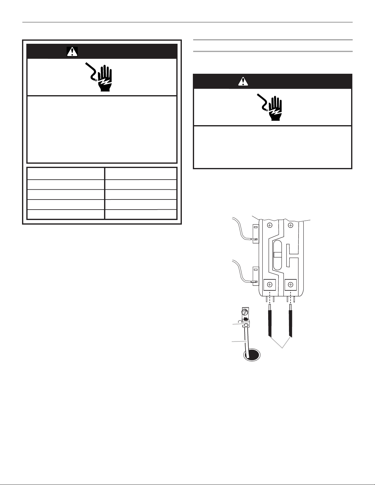
Single Phase Electrical Connections
Refer to Wiring Connection Diagram—Single Phase 208/230 Volt
later in this section.
WARNING
Electrical Shock Hazard
Disconnect power before servicing.
Replace all parts and panels before operating.
Failure to do so can result in death or electrical shock.
Rating Plate Ampacity
Less than 15
16 - 20
21 - 30
31 - 50
IMPORTANT:
■ Electrical wiring, disconnect means and over-current
protection are to be supplied by the installer. Refer to the
rating plate for the maximum over-current protection,
minimum circuit ampacity, and operating voltage. See the
wiring diagrams later in this section.
■ Install an adequately-sized branch circuit disconnect,
according to the NEC, within sight of and readily accessible
from the condensing unit.
■ The cable or conduit and fittings connected from the
disconnect to the condensing unit shall be rated for outdoor
use.
■ Check the condensing unit rating plate to determine whether
the system is rated single phase or three phase and follow
the appropriate instructions below.
AWG
14
12
10
8
1. Disconnect power.
2. Remove control box cover.
3. Connect the field supply wires L1 and L2 to contactor
terminals L1 and L2.
4. Connect ground wire to ground lug.
T1T2
L1L2
A
L1L2
B
A. Ground lug
B. Field supply ground wire
C. 208/230 volt field supply wires
5. Connect low voltage circuit.
C
5
Page 6
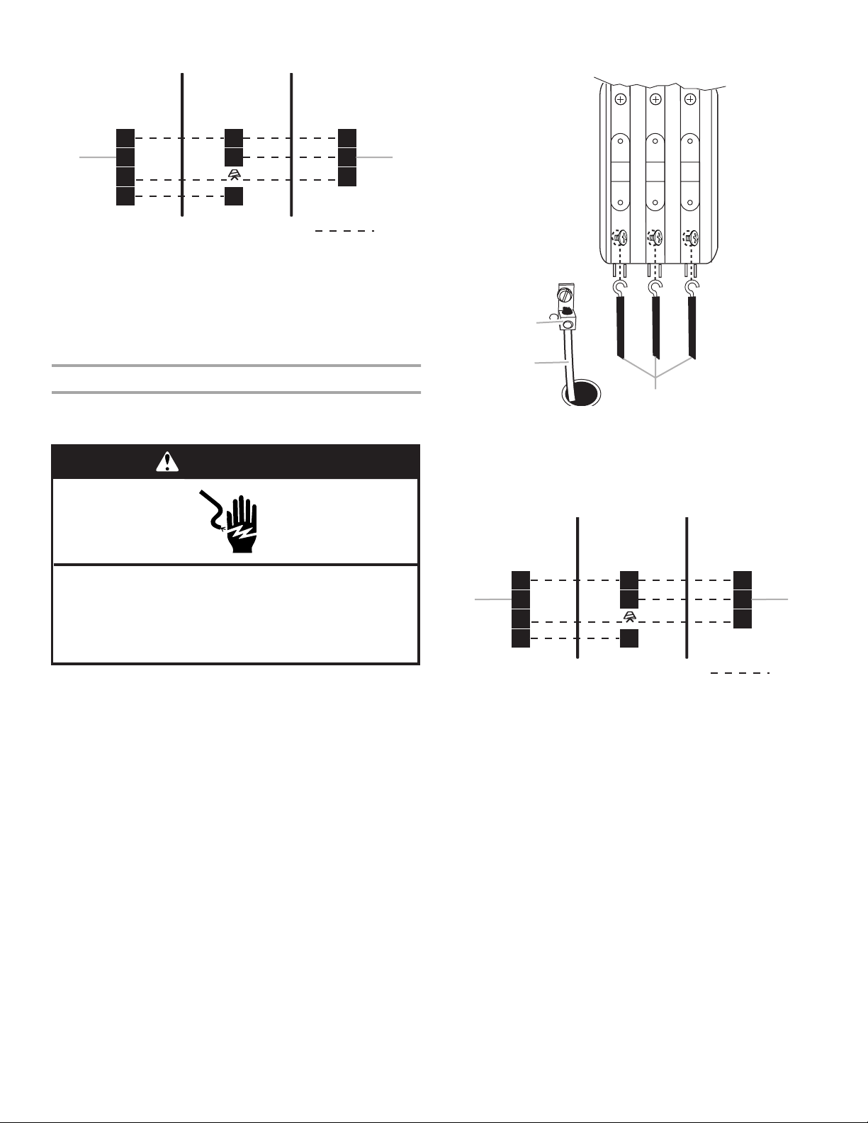
Typical Wiring Connection (low voltage circuit)
B
B
Thermostat
Indoor Unit
Outdoor Unit
4. Connect ground wire to ground lug.
T2
T1
T3
R
A
C
R
C
Y
G
24V Control Wiring (NEC Class 2)
A. Do not connect C (common) connection between indoor unit and
thermostat except when required by the indoor thermostat. Refer
to the thermostat installation instructions.
B. C (common) connection between indoor unit and outdoor unit
required for proper operation.
G
R
C
Y
6. Replace control box cover.
7. Reconnect power.
Three Phase Electrical Connections
Refer to Wiring Connection Diagram—Three Phase 208/230 Volt
later in this section.
WARNING
L1
L2
L3
A
L3L2L1
B
C
A. Ground lug
B. Field supply ground wire
C. 208/230 volt field supply wires
5. Connect low voltage circuit.
Typical Wiring Connection (low voltage circuit)
Thermostat
Indoor Unit
Outdoor Unit
Electrical Shock Hazard
Disconnect power before servicing.
Replace all parts and panels before operating.
Failure to do so can result in death or electrical shock.
NOTE: Check compressor operation for proper rotation. If the
rotation is not correct, then reverse any two leads (for example:
L1 and L2). Incorrect rotation is identified by excessive sound or
improper system pressures.
1. Disconnect power.
2. Remove control box cover.
3. Connect the field supply wires L1, L2 and L3 to contactor
terminals L1, L2 and L3.
R
A
C
R
C
Y
G
24V Control Wiring (NEC Class 2)
A. Do not connect C (common) connection between indoor unit and
thermostat except when required by the indoor thermostat. Refer
to the thermostat installation instructions.
B. C (common) connection between indoor unit and outdoor unit
required for proper operation.
G
R
C
Y
6. Replace control box cover.
7. Reconnect power.
6
Page 7
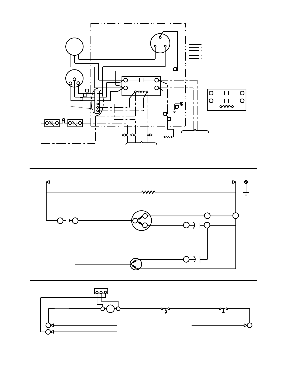
Wiring Connection Diagram—Single Phase 208/230 Volt
Comfort Alert
(When Used)
Discharge
Thermostat
(When Used)
High Pressure Switch
Schematic of Power Circuit
Fan
BR
BK
V
Comp
C
S
R
Y
BK
R
(When Used)
Com
Fan
Comp
Run
Cap
Herm
Line Voltage - Factor y
Line Voltage - Factor y When Used
Line Voltage - Field
Low Voltage - Factor y
Low Voltage - Factor y When Used
Low Voltage - Field
R
Contactor
T1 L1
S
T2
C
R
R
C
Y
Connect to "C," "Y" and "R" terminals
of indoor control circuit having minimum
40 VA, 24 volt NEC Class II transformer.
Outdoor Power Supply
Crankcase Heater
(When Used)
L2
BK
G
BK
Crankcase
Heater
(When Used)
Ground
Wire
R
To single phase power
supply per rating plate
with minimum 167ºF
copper wire only. Circuit
protection per rating plate.
NOTE: If the original wire is
replaced, the same size and
type wire must be used.
T1
T2
Alt.
Contactor
L1
L2
Ground
Wire
L1
Contactor
Typical Schematic of Control Circuit
Y
R
R
S
Compressor
Motor
Discharge Thermostat
(When Used)
H
Dual
Capacitor
C
F
High Pressure Switch
(When Used)
T1
R
Y
C
Compressor
Contactor Coil
C
Fan
Motor
L2T2
Thermostat Terminals
7
Page 8
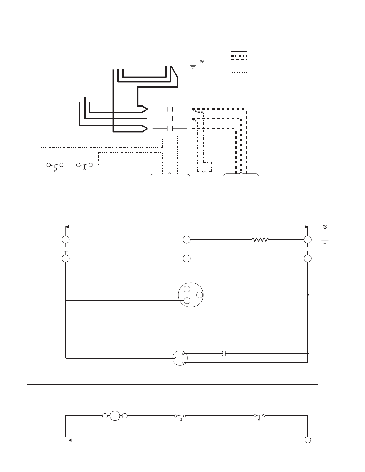
Wiring Connection Diagram—Three Phase 208/230 Volt
Connection Diagram
Comp
T3
R
Fan
Motor
BK
T2
T1
BR
BK
Capacitor
BR
V
R
Contactor
T1
T2
T3
Y
Y
Fan
Line Voltage - Factory
Line Voltage - Factory (If Used)
Line Voltage - Field
Ground
Screw
L1
L2
L3
BK
Y
BK
Low Voltage - Factory
Low Voltage - Factory (If Used)
Low Voltage - Field
Discharge
Thermostat
(If Used)I
High Pressure Switch
(If Used)
Schematic of Power Circuit
L3
Compressor
Contactor
T3
Connect to "C" and "Y"
terminals of indoor control
circuit having minimum
40 VA, 24 volt NEC Class II
Transformer.
Outdoor Power Supply
L2
T2
Compressor
Motor
Fan
Motor
T2
T3
Crankcase Heater
(If Used)
T1
Refer to rating plate for
line voltage 3 phase
power supply. Use minimum
167ºF copper wire only.
Crankcase Heater
(If Used)
Ground
Screw
L1
T1
Typical Schematic of Control Circuit
8
Compressor
Contactor Coil
Discharge Thermostat
(If Used)
Thermostat Terminals
High Pressure Switch
(If Used)
Page 9

Complete Installation
1. Operate the condensing unit for a period of at least
15 minutes to allow for pressures and temperatures to
stabilize.
2. If condensing unit does not appear to be functioning
correctly, have condensing unit checked by a person certified
by the EPA to handle refrigerant.
SEQUENCE OF OPERATION
Upon cooling demand, the thermostat closes circuit R to Y.
Closing R to Y energizes the condenser for cooling operation and
closes the unit contactor, starting the compressor and outdoor
fan. The thermostat automatically closes R to G circuit which also
brings on the indoor fan at the same time. Upon satisfying
cooling demand, the thermostat will open the above circuits and
open the main contactor, stopping the compressor and outdoor
fan. If the indoor unit is equipped with a delay timer, the blower
will continue to operate for 60 - 90 seconds, which improves
system efficiency.
SYSTEM MAINTENANCE
■ Leaves and other large obstructions should be removed from
the condensing unit surfaces without damaging the fin
surface of the coil.
■ Routinely clean or change the indoor air filter. Should the
indoor coil become dirty, thus restricting airflow, call a
qualified service person to clean the coil surface.
■ An annual inspection by a qualified person should be
performed to ensure continued high-quality performance.
ASSISTANCE OR SERVICE
If you need further assistance, you can write to the below
address with any questions or concerns:
Whirlpool
14610 Breakers Drive
Jacksonville, FL 32258
Please include a daytime phone number in your correspondence.
®
Home Cooling and Heating
9
Page 10

Notes
10
Page 11
11
Page 12

Keep this book and your sales slip together for future
reference. You must provide proof of purchase or installation
date for in-warranty service.
Write down the following information about your Split System
Condensing Unit to better help you obtain assistance or service if
you ever need it.
Dealer name____________________________________________________
Address ________________________________________________________
Phone number __________________________________________________
Model number __________________________________________________
Serial number __________________________________________________
Installation date ________________________________________________
100402-03
© 2005. All rights reserved.
Manufactured under license by Tradewinds Distributing Company, LLC., Coconut Grove, Florida
®Registered Trademark/TM Trademark of Whirlpool, U.S.A.,
Printed in U.S.A.
11/05
 Loading...