

Whirlpool W10153554 User Manual [en, es, fr]
BOTTOM MOUNT BUILT-IN REFRIGERATOR
ACCESSORY GRILLE INSTALLATION INSTRUCTIONS
INSTRUCCIONES DE INSTALACIÓN DE LA REJILLA
ACCESORIA DEL REFRIGERADOR EMPOTRADO
CON MONTAJE INFERIOR
INSTRUCTIONS D'INSTALLATION DE LA GRILLE
ACCESSOIRE POUR RÉFRIGÉRATEUR ENCASTRÉ
(AVEC CONGÉLATEUR EN BAS)
Table of Contents/Índice/Table des matières
ACCESSORY GRILLE AND
HEATER SAFETY............................................. 1
INSTALLATION REQUIREMENTS................. 2
Tools and Parts............................................ 2
Plan the Installation...................................... 2
Location Requirements............................... 3
INSTALLATION INSTRUCTIONS................... 4
Remove Existing Top Grilles....................... 4
Install the Heaters........................................ 4
CREATE CUSTOM PANEL.............................8
Custom Panel for a
One-piece Accessory Grille......................... 8
Custom Panel for Overlay Accessory Grille 8
ASSEMBLE ACCESSORY GRILLE................9
One-piece Accessory Grille......................... 9
Two-piece Accessory Grille......................... 9
INSTALL ACCESSORY GRILLE................... 10
One-piece Accessory Grille....................... 10
Two-piece Accessory Grille....................... 10
Wiring Connection Diagram...................... 11
SEGURIDAD DE LA REJILLA
ACCESORIA Y DEL CALENTADOR............12
REQUISITOS DE INSTALACIÓN .................12
Piezas y herramientas................................12
Planee la instalación...................................13
Requisitos de ubicación.............................13
INSTRUCCIONES DE INSTALACIÓN......... 14
Quite las rejillas superiores existentes.......14
Instale los calentadores .............................14
CÓMO CREAR PANELES A LA MEDIDA... 18
Panel a la medida para una rejilla
accesoria de una pieza ..............................18
Panel a la medida para rejilla
accesoria recubierta...................................18
CÓMO ENSAMBLAR LA REJILLA
ACCESORIA...................................................19
Rejilla accesoria de una pieza....................19
Rejilla accesoria de dos piezas..................19
CÓMO INSTALAR LA
REJILLA ACCESORIA................................... 20
Rejilla accesoria de una pieza....................20
Rejilla accesoria de dos piezas..................20
Diagrama de conexión de cableado..........21
SÉCURITÉ DE LA GRILLE ACCESSOIRE
ET DE L'ÉLÉMENT CHAUFFANT................ 22
EXIGENCES D'INSTALLATION ...................22
Outillage et pièces ..................................... 22
Planification de l'installation ......................23
Exigences d'emplacement ........................ 23
INSTRUCTIONS D'INSTALLATION.............24
Dépose des grilles supérieures existantes 24
Installation des éléments chauffants......... 24
RÉALISATION DES PANNEAUX
PERSONNALISÉS .........................................28
Panneau personnalisé pour grille
accessoire monopièce...............................28
Panneau personnalisé pour grille
accessoire frontale..................................... 28
ASSEMBLAGE DE
LA GRILLE ACCESSOIRE............................29
Grille accessoire monopièce .....................29
Grille accessoire en deux parties ..............29
INSTALLATION DE
LA GRILLE ACCESSOIRE............................30
Grille accessoire monopièce .....................30
Grille accessoire en deux parties ..............30
Schéma de câblage................................... 31
ACCESSORY GRILLE AND HEATER SAFETY
Your safety and the safety of others are very important.
We have provided many important safety messages in this manual and on your appliance. Always read and obey all safety
messages.
This is the safety alert symbol.
This symbol alerts you to potential hazards that can kill or hurt you and others.
All safety messages will follow the safety alert symbol and either the word “DANGER” or “WARNING.”
These words mean:
You can be killed or seriously injured if you don't immediately
DANGER
WARNING
All safety messages will tell you what the potential hazard is, tell you how to reduce the chance of injury, and tell you what can
happen if the instructions are not followed.
2300108
follow instructions.
can be killed or seriously injured if you don't
You
instructions.
follow

INSTALLATION REQUIREMENTS
WARNING
Excessive Weight Hazard
Use two or more people to move and install grille kit.
Failure to do so can result in back or other injury.
The accessory grille provides a custom, unified appearance to
two 36" (91.4 cm) bottom-mount refrigerators installed next to
each other. The accessory grille replaces each refrigerator’s top
grille.
These instructions are intended as a general guide only and do
not supersede any national or local codes in any way.
Compliance with all local, state or national codes pertaining to
this type of installation should be determined prior to installation.
Tools and Parts
Assemble the required tools and parts before starting installation.
Read and follow the instructions provided with any of the
required tools listed here. Proper installation is your responsibility.
Tools Needed:
■ ¹⁄₄" Nut driver
■ Power screwdriver
■ Tape measure
Parts Supplied:
The Accessory Grille Kit includes all parts needed for installation
on any model.
Heater Parts (All models)
■ Black wire and white wire
harness
■ Black wire and orange wire
harness
■ Tran sf or me r
■ Foil-type heaters (2)
■ Wiring diagram - See “Wiring
Connection Diagram.”
■ ¹¹⁄₃₂" Nut driver
■ Scissors
■ Ta pe
■ Tran sf or me r
mounting template
(Back Cover)
■ #8–13 x ¹⁄₂" Self-
drilling screws (2)
Additional Parts for One-piece Accessory Grille
■ Accessory grille top
■ Accessory grille bottom
■ Accessory grille end caps (2)
■ Center mounting bracket
■ T-b o lt s an d n ut s (6 )
■ Acrylic panel and filler
(optional)
Additional Parts for Two-piece Accessory Grille
■ Accessory grille
■ Louver panel
■ Mounting bracket
■ Mounting bracket screw
■ Tab brackets (2)
■ Tab bracket screws (2)
Plan the Installation
Required parts, accessories and options
■ Two 36" bottom-mount refrigerators (a left-hand swing and a
right-hand swing)
■ Accessory Grille Kit with Heaters. See “Tools and Parts.”
■ Custom Panels (optional depending on your model)
Plan the installation of the two refrigerators using both these
instructions and the Installation Instructions provided with the
refrigerators. Both heaters must be installed on the refrigerators
before they are moved into their final locations.
NOTE: For the proper opening dimensions and utility placement
when installing two bottom-mount refrigerators next to each
other. See “Location Requirements.”
2
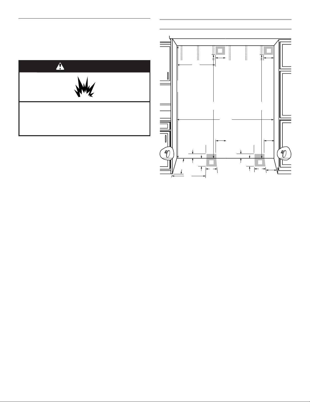
Location Requirements
These opening dimensions are specific to the installation of two
36" (91.4 cm) bottom-mount refrigerators side by side. The
refrigerators can be recessed into an opening between cabinets
or installed at the end of a cabinet run using a side panel to
enclose the refrigerators.
WARNING
Opening Dimensions
80" - 90"
(203-229 cm)
31¹⁄₂"
(80 cm)
83¹⁄₄" (211.5 cm) min.
84
³⁄₄" (215 cm) max.
to bottom of solid soffit
A A
80" - 90"
(203-229 cm)
4"
(10.2 cm)
4"
(10.2 cm)
Explosion Hazard
Keep flammable materials and vapors, such as
gasoline, away from refrigerator.
Failure to do so can result in death, explosion, or fire.
IMPORTANT:
■ Observe all governing codes and ordinances.
■ Do not install the refrigerators near an oven, radiator, or
other heat source, nor in a location where the temperature
will fall below 55°F (13°C).
■ Floor must support the combined refrigerator weights,
more than 1,200 lbs (544 kg), door panels and contents of
the refrigerator.
■ Ceiling height must allow for side or front tipping radius.
See “Tipping Radius” in the Installation Instructions
provided with the refrigerators.
■ Location should permit doors to open fully. See “Door
Swing Dimensions” in the Installation Instructions
provided with the refrigerators.
■ Location must permit top grille removal. See “Opening
Dimensions” in the “Location Requirements” section of
the Installation Instructions provided with the
refrigerators.
■ A grounded 3 prong electrical outlet should be placed
within 4" (10.2 cm) of the right side of each refrigerator.
See “Electrical Requirements” in the Installation
Instructions provided with the refrigerators.
■ The water shutoff should be located in the base cabinets
on either side of the refrigerators or some other easily
accessible area. If the water shutoff valve is not in the
cabinets, the plumbing for the water line can come
through the floor or the back wall. See “Water Supply
Requirements” in the Installation Instructions provided
with the refrigerators.
C
77"
(196 cm)
72"
(182.8 cm)
6"
(15.2 cm)
3" (7.6 cm)
11"
B B
23¹⁄₂"
(59.7 cm) min.
(28 cm)
6"
23¹⁄₂"
(59.7 cm)
A. Recommended electrical outlet locations
B. Recommended water line locations
C. Recommended water shutoff valve locations
(15.2 cm)
3" (7.6 cm)
(28 cm)
11"
77"
(196 cm)
(15.2 cm)
6"
(15.2 cm)
6"
6"
(15.2 cm)
C
3
INSTALLATION INSTRUCTIONS
B
B
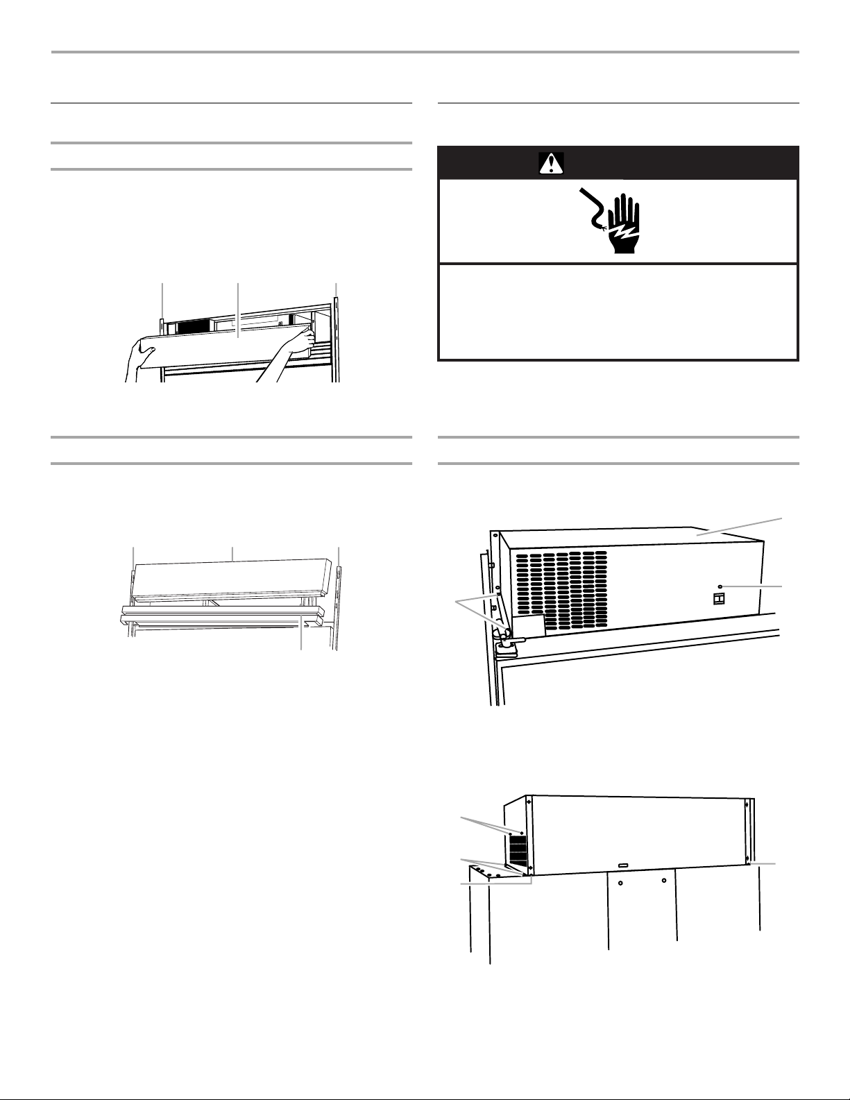
Remove Existing Top Grilles
One-piece Grilles
1. Grasp both ends of the top grille.
2. Push the top grille straight up and pull straight out from the
cabinet side trim.
3. Remove the top grille from the second refrigerator and
discard both top grilles.
B BA
A. Top grille
B. Cabinet side trim
Two-piece Grilles
1. Grasp both ends of the louver panel.
2. Push louver panel straight up and pull straight out from the
cabinet side trim.
AB
Install the Heaters
WARNING
Electrical Shock Hazard
Disconnect all power supplies before servicing.
Replace all parts and panels before operating.
Failure to do so can result in death or electrical shock.
To install the heater kit, you will need to disassemble the
compressor cover on the left-hinge refrigerator only. You will not
need to disassemble the compressor cover on the right-hinge
refrigerator.
Remove the Compressor Cover
1. Remove three screws from the front and side of the
compressor cover on the left-hinge refrigerator as shown.
A
C
A. Top grille
B. Cabinet side trim
C. Louver panel
3. Grasp both ends of the top grille.
4. Push the top grille straight up and pull straight out from the
cabinet side trim.
5. Remove the louver panel and top grille from the second
refrigerator.
6. Discard both louver panels and top grilles.
B
A. Compressor cover
B. Compressor cover screws
2. Remove six screws from the side and bottom back of the
compressor cover as shown.
A
A
A
A. Compressor cover screws
A
3. Lift the compressor cover up and off of the refrigerator.
4
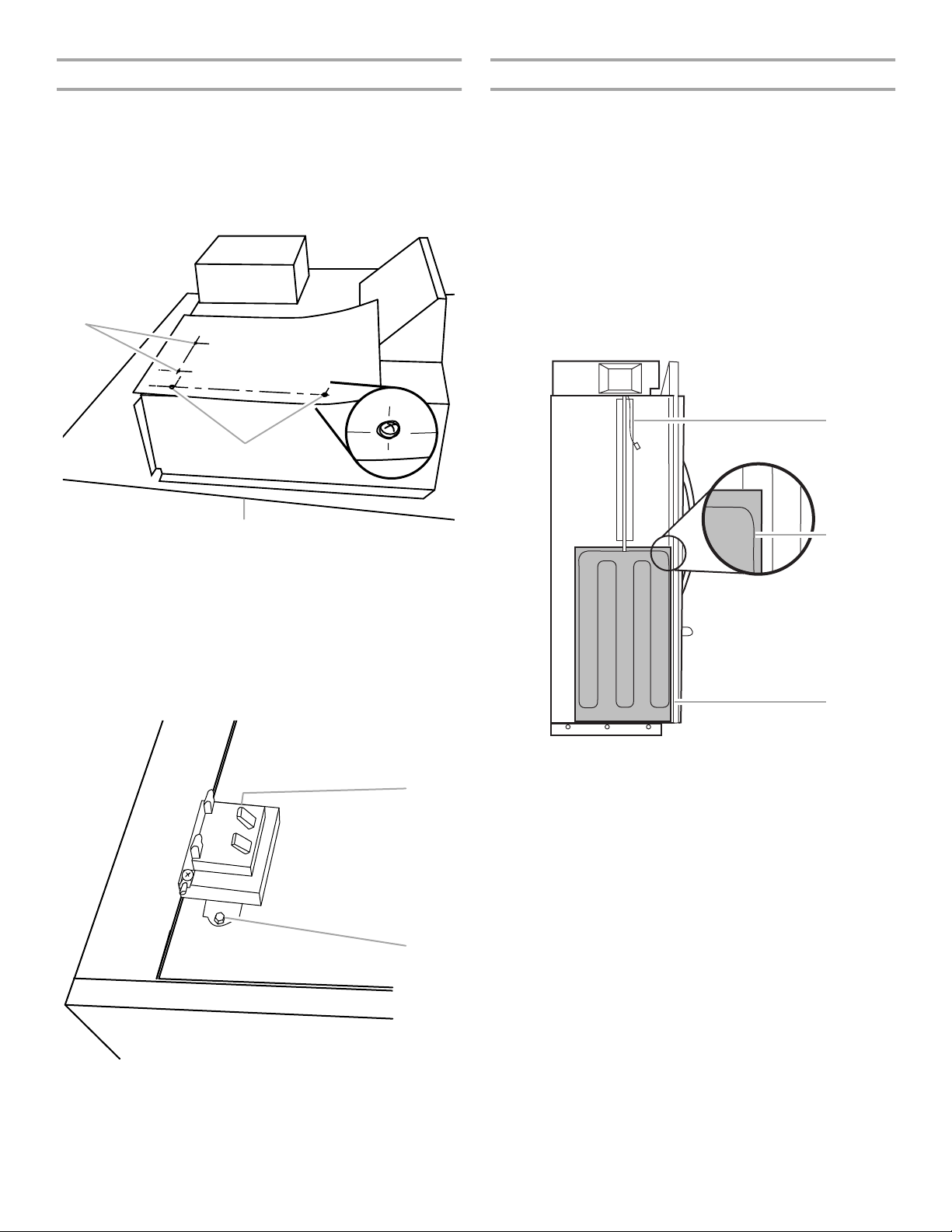
Install the Transformer
C
Attach the Heaters
1. Locate the Transformer Mounting Template included on the
back cover of these Installation Instructions.
2. Position the template at the back of the condenser cover,
using the two condenser cover screws as your guides.
3. Push the template down over the condenser cover screws to
hold it in place. Mark the locations for the transformer
mounting screws as shown.
A
B
C
A. Transformer mounting screw locations
B. Condenser cover screws
C. Back of the refrigerator
Locate the two foil-type heaters from the kit. Install one heater on
each refrigerator.
NOTE: The heaters will be between the two refrigerators when
they are moved into their final locations.
1. Align the bottom of the heater with the seam at the bottom of
the refrigerator.
2. Position the heater so the edge overlaps the cabinet side
trim, making sure one heater wire is touching the trim.
NOTE: The right-hinge refrigerator is shown.
3. Peel the backing off of the heater and adhere it to the side of
the refrigerator.
4. Tape the wires to the side of the refrigerator near the top to
aid in making the final wire connections after the refrigerators
are moved into their final locations.
A
B
4. Center punch the locations for the transformer mounting
screws.
5. Position the transformer on the condenser cover as shown.
Install the transformer using the self-drilling screws provided.
NOTE: Do not drill into the condenser cover. You could
damage the condenser. Use the self-drilling screws provided.
A
A
A. Heater wires taped to refrigerator
B. Heater wire touches cabinet side trim
C. Bottom of heater aligns with bottom seam
A. Transformer self-drilling screws
5
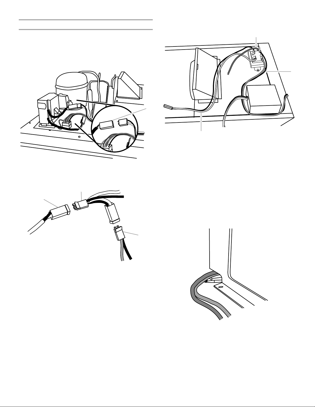
Connect the Wiring
A
5. Connect the green ground wire to the transformer and to the
ground screw as shown.
IMPORTANT: See the “Wiring Connection Diagram” while
performing the following procedure.
1. Locate the two-pin connector with the black wire and white
wire at the front of the compressor compartment.
2. Disconnect the two-pin connector with the black wire and
white wire.
A
A. Two-pin connector with black wire and white wire
3. Connect the new two-pin black wire and white wire provided
in the kit to the existing two-pin connector as shown.
B
A
A
B
C
A. Green ground wire
B. Black wire and orange wire
C. Black wire and white wire
6. Connect the heater wires (orange wire and black wire) to the
transformer as shown. Do not connect the heater wires to the
heaters until the refrigerators are in their final locations.
NOTE: Route the heater wires (orange wire and black wire)
around to the front of the compressor compartment where
they will exit through a notch in the bottom of the
compressor compartment cover.
7. Replace the compressor compartment cover.
NOTE: Route the heater wires (orange wire and black wire)
through the notch at the front of the compressor
compartment cover as shown. Be sure the wires are not
kinked or pinched.
A. Existing two-pin connector with
black wire and white wire
B. New two-pin connector with
black wire and white wire
4. Connect the new black wire and white wire to the transformer
as shown.
6
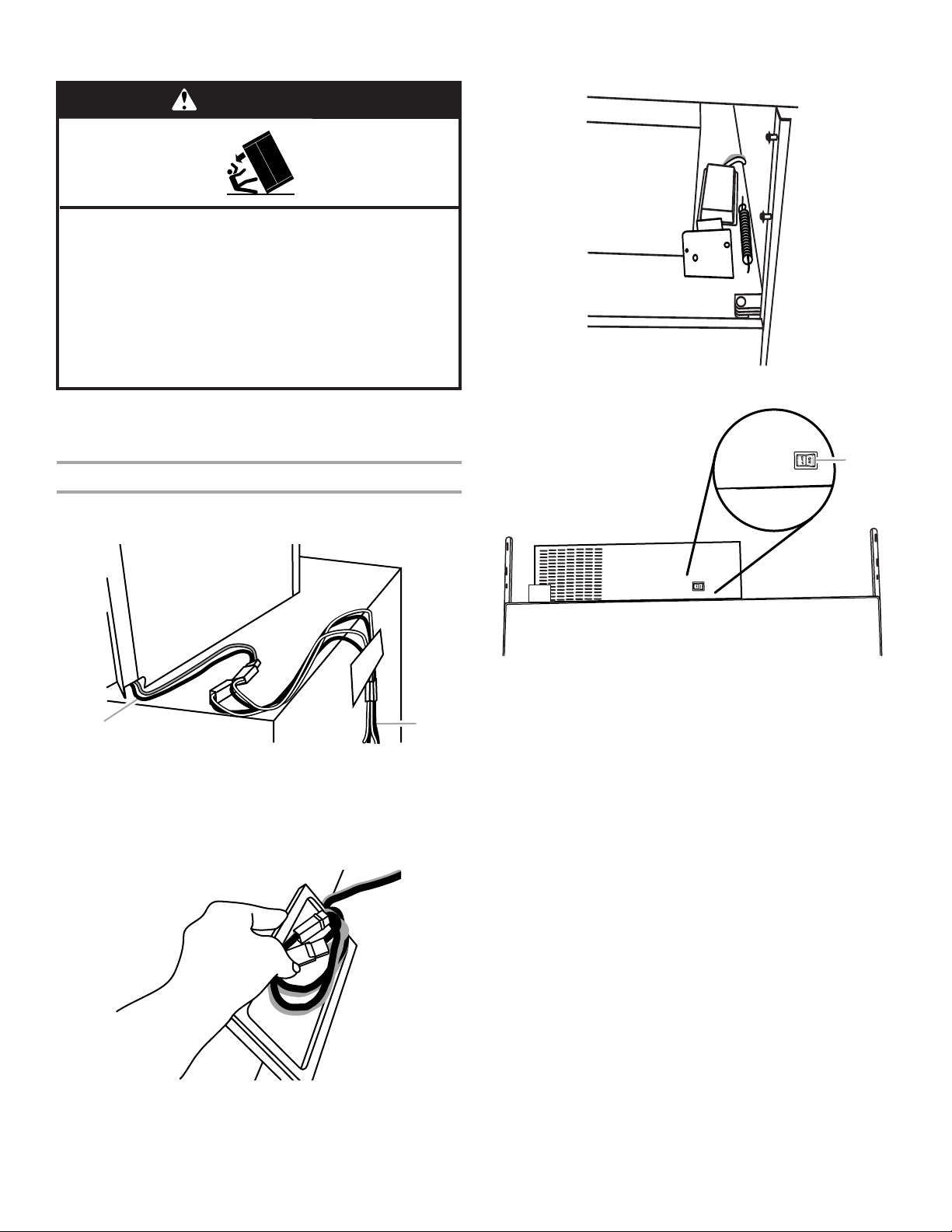
8. Plug refrigerators into grounded 3 prong outlets.
B
WARNING
Tip Over Hazard
Refrigerator is top heavy and tips easily when not
completely installed.
Keep doors taped closed until refrigerator is
completely installed.
Use two or more people to move and install
refrigerator.
Failure do so can result in death or serious injury.
9. Move the refrigerators to their final locations. Make sure that
heater wires (orange wire and black wire) are not kinked and
are on top of the refrigerators within easy reach.
Make Final Connections
1. Connect the heater wires (orange wire and black wire) to the
heaters as shown.
3. Press the connector cover down onto the top of the
refirigerator next to the compressor cover as shown.
4. Make sure the power disconnect switch is ON.
A
A
A. Heater wires (orange
wire and black wire)
B. Heaters
2. Remove the adhesive backing from the connector cover. Put
the heater wires (orange wire and black wire) and their
connectors inside the connector cover.
A. Power disconnect switch
7
CREATE CUSTOM PANEL
Custom Panel for a One-piece
Accessory Grille
NOTE: If you want to use the acrylic panel and filler provided,
skip this section.
To create a custom panel for a one-piece accessory grille, follow
these steps:
1. Match panel wood grain direction with that of adjacent
cabinets.
2. Cut the custom panel according to the dimensions shown.
NOTE: A ¹⁄₄" (6.35 mm) thickness can be used for wood
panels. If you wish to use thicker material, the edges must be
routed to ¹⁄₄" (6.35 mm).
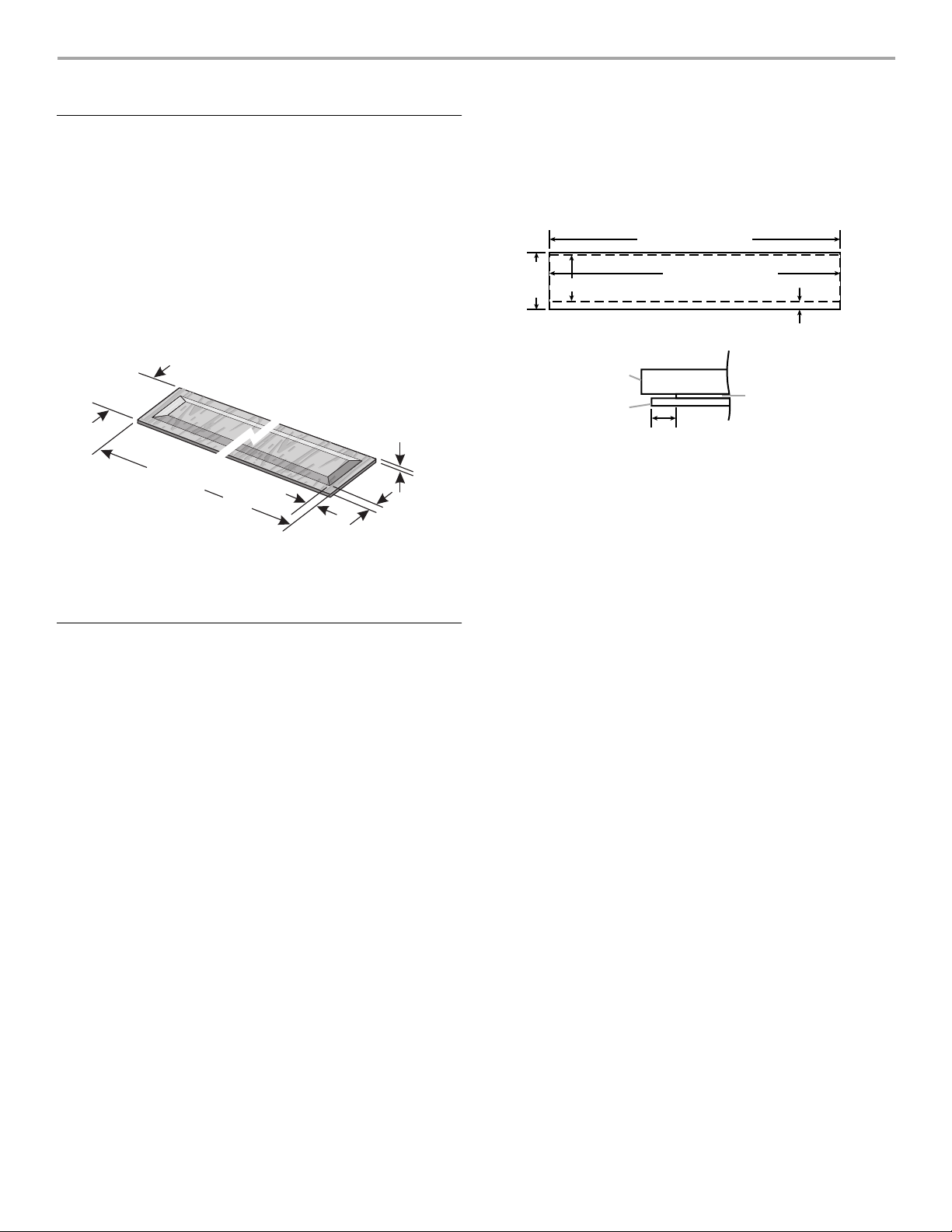
To create custom panels for an overlay accessory grille, follow
these steps:
1. Cut and assemble the overlay and backer panels to the
dimensions shown.
NOTE: A ¹⁄₄" (6.35 mm) backer panel is shown as a dotted
line.
70³⁄₄" (179.71 cm)
¹⁄₂"
8
(21.6 cm)
7³⁄₈" (18.7 cm)
70³⁄₄" (179.71 cm)
1" (2.54 cm)
7¹⁄₄"
(18.4 cm)
¹⁄₄" Max.
(6.4 mm)
³⁄₄"
70
(179.71 cm)
⁷⁄₈" Min.
(22.23 mm)
³⁄₈" Min.
(9.35 mm)
3. Use a moisture-resistant sealer on the sides and edges of the
panels to protect them from humidity.
4. See “Assemble Accessory Grille.”
Custom Panel for Overlay Accessory Grille
It is common to work with three panels: a decorative overlay
panel, a ¹⁄₈" (3.18 mm) spacer panel or spacer strips, and a ¹⁄₄"
(6.35 mm) backer panel. In some cases, your cabinet
manufacturer may choose to work with one panel routed for the
different dimensions. Follow these panel dimensions and
placement instructions to ensure that the custom overlay panel
fits properly.
NOTE: Panel weight should not exceed 20 lbs (9 kg). To minimize
panel weight, you may use 2" (5.08 mm) spacer strips around the
perimeter instead of full-sheet solid spacer panels. The spacer
strips must be set in at least 1" (2.54 cm) from the edge of the
backer panel.
A
C
1"
(2.54 cm)
A.
³⁄₄
" Decorative panel (19.05 mm)
¹⁄₈
" Spacer (3.18 mm)
B.
C.
¹⁄₄
" Backer Panel (6.35 mm)
B
2. Use moisture-resistant sealer on the sides and edges of the
panels to protect them from humidity.
3. See “Assemble Accessory Grille.”
8
ASSEMBLE ACCESSORY GRILLE
B
One-piece Accessory Grille
To assemble the accessory grille, follow these steps:
1. Insert the T-bolts and nuts into the top and bottom pieces of
the frame.
2. Attach one end cap to the top and bottom pieces of the
frame, and secure it with the T-bolts and nuts.
NOTE: Be sure the hooks on the end cap point toward the
bottom piece of the frame.
A
C
D
A. Bottom piece of the frame
B. T-bolts and nuts
C. End cap
D. Top piece of the frame
3. From the open end of the frame, insert the T-bolts without
nuts into the top and bottom pieces of the frame. Attach the
mounting bracket to the T-bolts using the nuts, but do not
fully tighten them.
NOTE: Be sure the hooks on the end cap point toward the
bottom piece of the frame.
4. Slide the mounting bracket toward the center of the frame.
The center of the hook on the bracket should be 36"
(91.4 cm) from the outside edge of the frame as shown.
Tighten the nuts on the T-bolts.
B
NOTE: Only kits with an acrylic panel require a filler panel.
A
A. Filler panel
6. Insert the remaining T-bolts and nuts into the top and bottom
pieces of the frame.
7. Attach the other end cap and secure it with the T-bolts and
nuts.
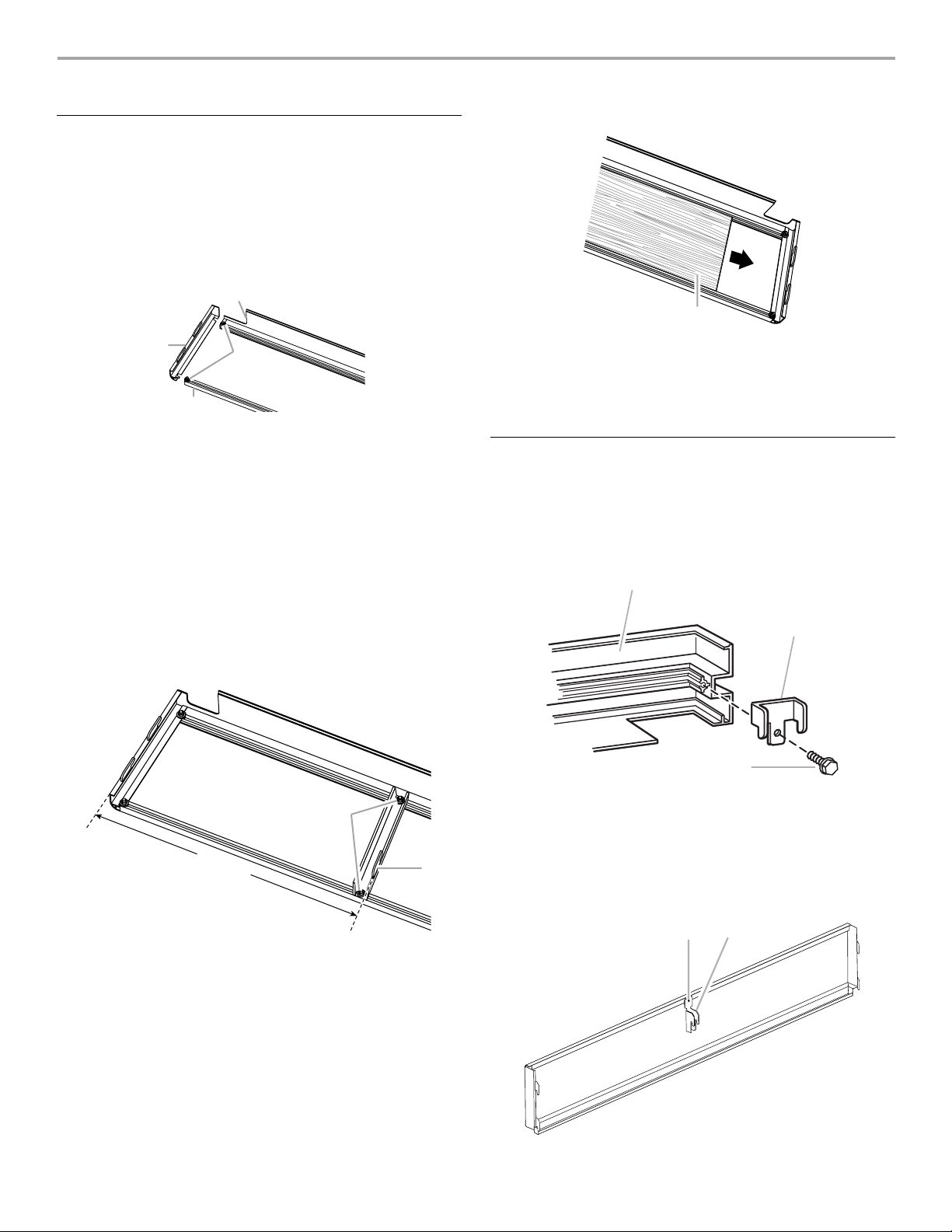
Two-piece Accessory Grille
To assemble the louver panel and accessory grille, follow these
steps:
1. Place the louver panel on a clean, nonabrasive surface.
2. Install a tab bracket on each end using the screws provided,
making sure the tabs are aligned properly.
A
B
A
36"
(91.4 cm)
A. T-bolts and nuts
B. Hook
5. Slide the custom panel or acrylic and filler panels into the
open end of the frame.
C
A. Louver panel
B. Tab bracket
C. Bracket mounting screw
3. Place the accessory grille face down on a clean, nonabrasive
surface.
4. Attach the mounting bracket to the back of the accessory
grille as shown.
AB
A. Mounting bracket screw
B. Mounting bracket
9
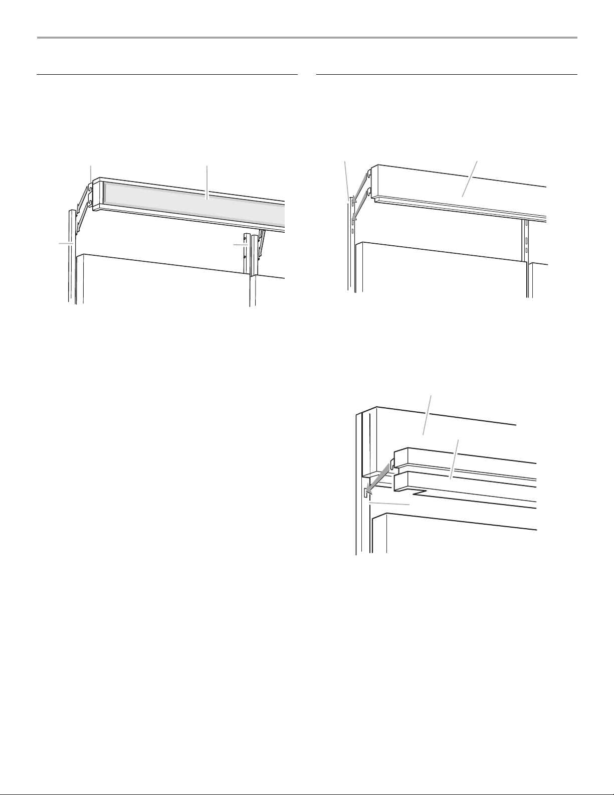
INSTALL ACCESSORY GRILLE
One-piece Accessory Grille
1. Lift the accessory grille into position and align the hooks with
the shoulder screws in the refrigerator frame.
2. Slide the hooks over the shoulder screws and push down as
shown. Make sure the accessory grille is firmly in place.
B
A
A. Refrigerator frame
B. Bracket tabs
C. Accessory grille
C
A
Two-piece Accessory Grille
1. Lift accessory grille into position and align the hooks with the
slots in the refrigerator frame.
2. Slide the hooks into the slots and push down as shown.
Make sure the accessory grille is firmly in place.
B
A. Accessory grille
B. Refrigerator frame
3. Lift the louver panel into position and align the hooks with the
slots in the refrigerator frame.
4. Slide the hooks into the slots and push down as shown.
Make sure the accessory grille is firmly in place.
A
A
B
C
A. Accessory grille
B. Louver panel
C. Refrigerator frame
5. Remove protective film from the accessory grille.
10
 Loading...