

Whirlpool W10120482A User Manual
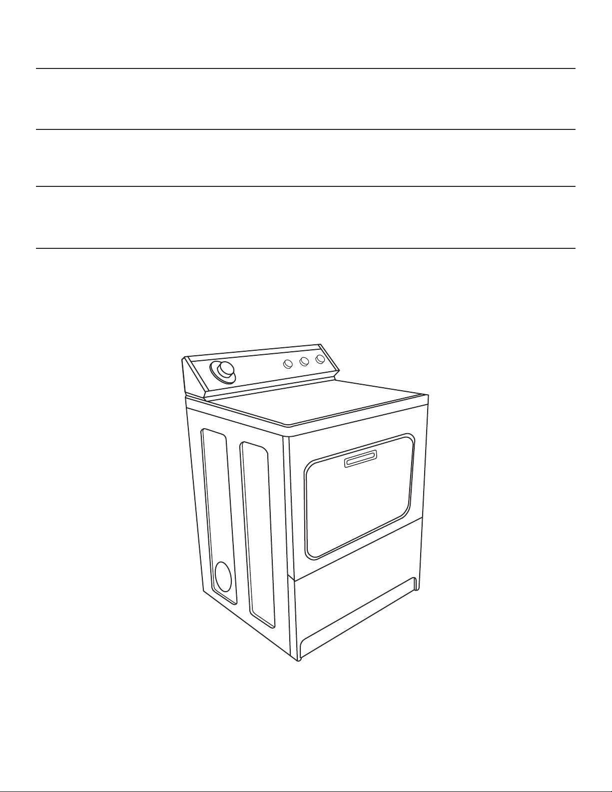
INSTALLATION INSTRUCTIONS
GAS DRYER
W10120482A
IMPORTANT: Save these instructions.
IMPORTANTE:
Guarde estas instrucciones.
IMPORTANT :
Conserver ces instructions.
Table of Contents . . . . . . . . . . . . . . . . . . . . . . . . . . . . . . . . . . . . . . . . . . . . . . . . . . . . . . . .2
Índice . . . . . . . . . . . . . . . . . . . . . . . . . . . . . . . . . . . . . . . . . . . . . . . . . . . . . . . . . . . . . . . . 12
Table des matières . . . . . . . . . . . . . . . . . . . . . . . . . . . . . . . . . . . . . . . . . . . . . . . . . . . . . . 22
INSTRUCCIONES DE INSTALACIÓN
SECADORA A GAS
INSTRUCTIONS D'INSTALLATION
SECHE-LINGE A GAZ
2
TABLE OF CONTENTS
DRYER SAFETY
DRYER SAFETY .......................................................................... 2
INSTALLATION REQUIREMENTS .............................................. 4
Tools and Parts .......................................................................... 4
Location Requirements.............................................................. 4
Electrical Requirements ............................................................ 6
Gas Requirements...................................................................... 6
Venting Requirements .............................................................. 7
INSTALLATION INSTRUCTIONS – GAS DRYER .................... 9
Install Ventwork ..........................................................................9
Prepare Dryer..............................................................................9
Level and Exhaust the Dryer ....................................................10
Check Operation ......................................................................11
Your safety and the safety of others are very important.
We have provided many important safety messages in this manual and on your appliance. Always read and obey all safety
messages.
This is the safety alert symbol.
This symbol alerts you to potential hazards that can kill or hurt you and others.
All safety messages will follow the safety alert symbol and either the word “DANGER” or “WARNING.”
These words mean:
You can be killed or seriously injured if you don't immediately
DANGER
WARNING
follow instructions.
can be killed or seriously injured if you don't
You
instructions.
follow
All safety messages will tell you what the potential hazard is, tell you how to reduce the chance of injury, and tell you what can
happen if the instructions are not followed.
IMPORTANT SAFETY INSTRUCTIONS
To reduce the risk of fire, electric shock, or injury to persons when using the dryer, follow basic precautions,
WARNING:
including the following:
■ Read all instructions before using the dryer.
■ Do not place items exposed to cooking oils in your dryer.
Items contaminated with cooking oils may contribute to
a chemical reaction that could cause a load to catch fire.
■ Do not dry articles that have been previously cleaned in,
washed in, soaked in, or spotted with gasoline, drycleaning solvents, other flammable, or explosive
substances as they give off vapors that could ignite or
explode.
■ Do not allow children to play on or in the dryer. Close
supervision of children is necessary when the dryer is
used near children.
■ Before the dryer is removed from service or discarded,
remove the door to the drying compartment.
■ Do not reach into the dryer if the drum is moving.
■ Do not install or store the dryer where it will be exposed
to the weather.
■ Do not tamper with controls.
■ Do not repair or replace any part of the dryer or attempt
any servicing unless specifically recommended in this
Use and Care Guide or in published user-repair instructions that you understand and have the skills to carry out.
■ Do not use fabric softeners or products to eliminate static
unless recommended by the manufacturer of the fabric
softener or product.
■ Do not use heat to dry articles containing foam rubber or
similarly textured rubber-like materials.
■ Clean lint screen before or after each load.
■ Keep area around the exhaust opening and adjacent sur-
rounding areas free from the accumulation of lint,dust,
and dirt.
■ The interior of the dryer and exhaust vent should be
cleaned periodically by qualified service personnel.
SAVE THESE INSTRUCTIONS
3
WARNING: For your safety, the information in this manual must be followed to minimize
the risk of fire or explosion, or to prevent property damage, personal injury, or death.
–Do not store or use gasoline or other flammable vapors and liquids in the vicinity of this
or any other appliance.
–WHAT TO DO IF YOU SMELL GAS:
•
Do not try to light any appliance.
•
Do not touch any electrical switch; do not use any phone in your building.
•
Immediately call your gas supplier from a neighbor's phone. Follow the gas supplier's
instructions.
•
If you cannot reach your gas supplier, call the fire department.
–Installation and service must be performed by a qualified installer, service agency, or
the gas supplier.
•
Clear the room, building, or area of all occupants.
4
Location Requirements
IMPORTANT: Observe all governing codes and ordinances.
■ Check code requirements: Some codes limit or do not permit
installation of clothes dryers in garages, closets, or sleeping
quarters. Contact your local building inspector.
INSTALLATION REQUIREMENTS
Tools and Parts
Gather the required tools and parts before starting installation.
Read and follow the instructions provided with any tools
listed here.
Tools needed
■ Flat-blade screwdriver
■ Phillips screwdriver
■ Adjustable wrench that opens to 2.5 cm (1")
■ 2.5 cm (1") Hex-head socket wrench
■ Level
■ 20 or 30 cm (8" or 10") pipe wrench
■ 1/4" socket wrench or 1/4" nut driver
■ Utility knife
■ Vent clamps
■ Pipe-joint compound resistant to LP gas
■ Caulk gun and caulk (for installing new exhaust vent)
■ Tin snips
Parts supplied
Remove parts bag from dryer drum. Check that all parts were
included.
■ 4 leveling legs
■ 4 gas inlet pipe adapters
Parts needed
Check local codes and gas supplier, and read electrical,
gas and venting requirements before purchasing parts.
Gas supply line must have:
• Shutoff valve
Rigid gas supply line must be:
• Minimum 12.5 mm (1/2") ID pipe
Flexible gas supply hose must be:
• Minimum 10 mm (3/8") ID approved flexible hose
L.P. gas conversion:
Gas conversion kit, part number 279918, available for
purchase from your dealer. Full instructions are supplied
with the kit. Conversion must be made by a competent
technician.
■ Make sure that lower edges of the cabinet, plus the back and
bottom sides of the dryer, are free of obstructions to permit
adequate clearance of air openings for combustion air. See
“Recessed Area and Closet Installation Instructions” for
minimum spacing requirements.
NOTE: The dryer must not be installed in an area where it will be
exposed to water and/or weather. If room temperature is below
7º C (45º F), automatic cycles may not shut off.
■ Maximum slope under entire dryer should not be more than
2.5 cm (1") . If slope is greater than 2.5 cm (1") , install
Extended Dryer Feet Kit, Part No. 279810. Clothes may not
tumble properly and automatic sensor cycles may not operate
correctly if dryer is not level. Floor must be able to support
dryer weight of 79.4 kg (175 lbs).
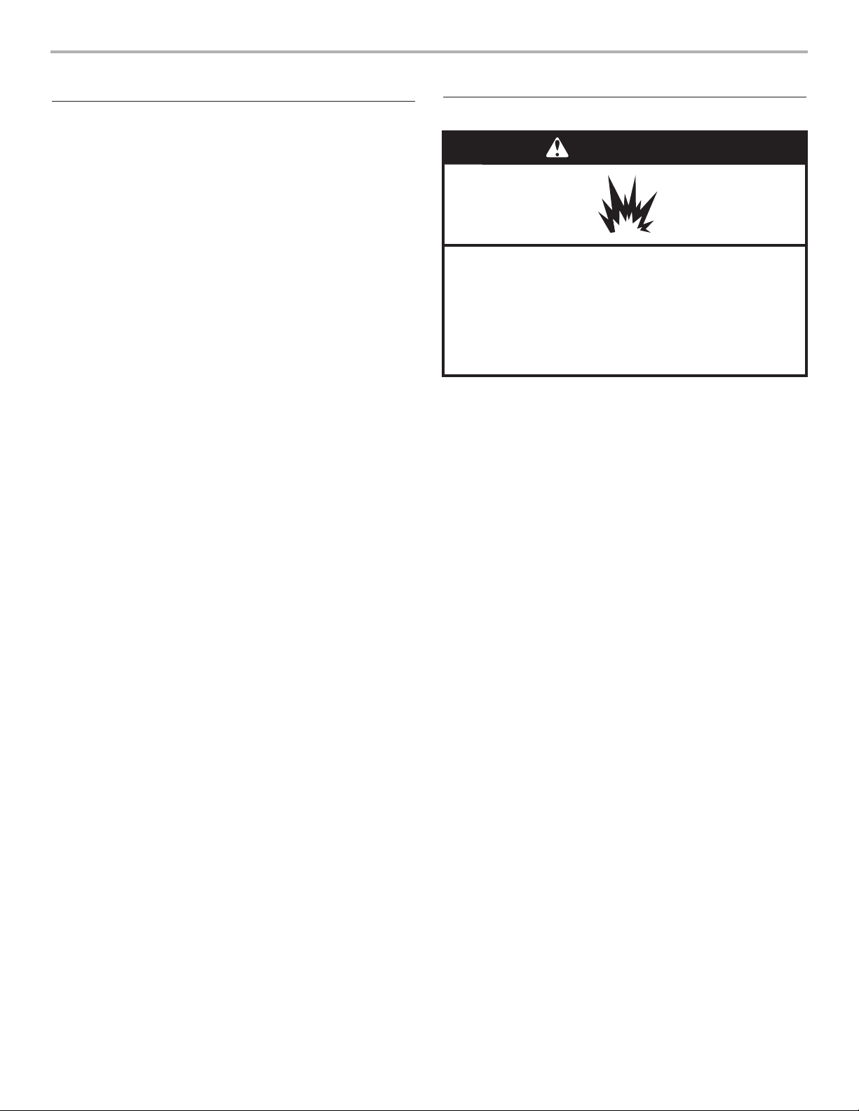
WARNING
Explosion Hazard
Keep flammable materials and vapors, such as
gasoline, away from dryer.
Place dryer at least 46 cm (18 inches) above the floor
for a garage installation.
Failure to do so can result in death, explosion, or fire.
5
Recessed Area and Closet Installation Instructions
This dryer must not be installed behind a lockable door, a sliding
door, or a door with a hinge on the opposite side to that of the
dryer.
This dryer may be installed in a recessed area or closet. For
recessed area and closet installations, minimum clearances can
be found on the serial tag on the dryer.
The installation spacing is in centimeters (inches) and is the
minimum allowable. Additional spacing should be considered for
ease of installation, servicing, and compliance with local codes
and ordinances.
If closet door is installed, the minimum unobstructed air opening
in the top and bottom is required. Louvered doors with equivalent
air openings are acceptable.
The dryer must be exhausted outdoors.
No other fuel-burning appliance may be installed in the same
closet as the dryer.
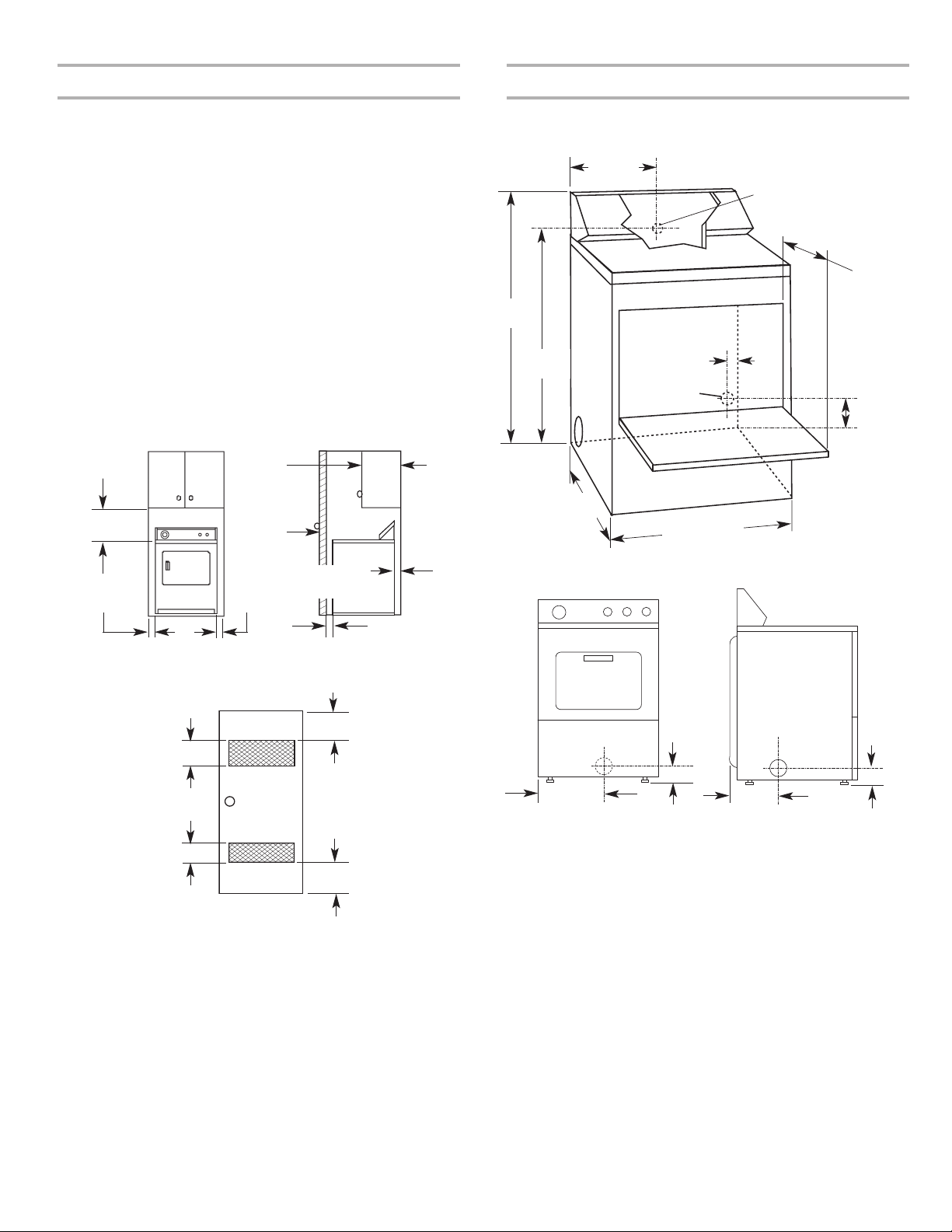
Recessed front view Closet side view
Minimum Installation Clearances
Additional clearances for wall, door and floor moldings may be required or if
external exhaust elbow is used.
closet
door
Front
View
7.6 cm (3")
7.6 cm (3")
155 cm
2
(24"2)
310 cm
2
(48"2)
*Opening is the minimum for a closet door.
Louvered doors with equivalent air openings are acceptable.
2.5 cm (1")
Closet
door
35.6 cm
(14") max.
2.5 cm (1")
2.5 cm (1")
45.7 cm
(18")*
10.2 cm
(4")
Product Dimensions
Dimensions shown with feet extended 2.5 cm (1") from
bottom of dryer.
left or right
side exhaust
back
exhaust
10.8 cm
(4-1/4")
26 cm
(10-1/4")
35.9 cm
(14-1/8")
10.2 cm
(4")
Exhaust dimensions
74.3 cm
(29-1/4")
An electrical outlet is
required within 1.4 m
(4-1/2 feet) for the
power supply cord
109.5 cm
(43-1/8")
27.9 cm
(11")
97.2 cm
(38-1/4")
68.6 cm (27")
35.6 cm (14")
door clearance
15.9 cm
(6-1/4")
3.8 cm
(1-1/2")
gas line
opening
6
Electrical Requirements Gas Requirements
Important: Observe all governing codes and ordinances.
This dryer is supplied/fitted with an electricity supply cord and
plug. It should be connected to electricity supply socket at the
voltage shown on the rating plate. The minimum supply fuse
capacity should be 5A. The dryer must be positioned so that the
plug is accessible. If the fitted plug is not used, the electrical
connection must be carried out by a competent electrician in
accordance with local or national codes.
If the supply cord is damaged, it must be replaced with a
specially terminated cord by an authorized service agent or a
similarly competent person.
Do not use an adapter.
Do not use an extension cord.
If codes permit and an additional earth bond wire is used, it is
recommended that a qualified electrician determine that the earth
bond, path is adequate.
OBSERVE ALL GOVERNING CODES AND ORDINANCES.
Gas supply:
Check that dryer is equipped with the correct burner for the
particular type of gas supply. Burner information will be found on
the model/serial rating plate in the door well of the dryer. If this
information does not agree with the type of gas available, see
your dealer.
Natural Gas:
This dryer is factory adjusted for use with NATURAL GAS (G20),
and no further adjustment should be required at installation.
L.P. Gas:
This dryer is also certified for use with L.P (propane or butane)
gases with appropriate conversion. No attempt shall be made to
convert the appliance from the gas specified on the model/serial
rating plate for use with a different gas without consulting the
serving gas supplier.
Conversion must be done by a competent service technician.
Gas conversion kit, part number 279918, is available for
purchase from your dealer. Full instructions are supplied with
the kit.
WARNING
Electric Shock Hazard
This is a 3-wire appliance which must be earthed.
Do not earth to a gas pipe.
Do not change the power supply cord plug. If it does
not fit the outlet, have a proper outlet installed by a
qualified electrician.
Do not use an extension cord with this dryer.
Failure to follow these instructions could result in
death, fire, or serious injury.
WARNING
Explosion Hazard
Connect this dryer to a regulated gas supply. Supply
pressure must be in accordance with the Technical
Specifications (see last page).
Install a shut-off valve.
Securely tighten all gas connections.
If connected to LP, have a qualified person make sure
gas pressure is correct.
Failure to do so can result in death, explosion, or fire.
7
Supply line requirements:
Provide a rigid gas supply line to the dryer location. It should be
minimum 12.5 mm (1/2"
) ID. When acceptable to the gas
supplier and local codes, 10 mm (3/8") ID rigid supply line may
be used for lengths under 6.1 m (20'). Pipe-joint compounds
resistant to the action of L.P gas must be used.
Gas connection to the dryer itself should be made by means of a
flexible gas hose suitable for the appliance and gas category in
accordance with national installation regulations. If in doubt,
contact the gas supplier. It should be minimum 10 mm (3/8") ID.
A means of restraint should be used between the appliance and
the wall to prevent straining of the rigid gas supply when the
appliance is moved. An appropriate length of chain and a wall
hook is recommended.
The dryer gas inlet connection is a 10 mm (3/8") NPT thread. An
adapter is supplied for conversion to standard ISO.228-1 thread
10mm (3/8" BSP).
Check for leaks by using an approved noncorrosive leakdetection solution. Bubbles will show a leak. Correct any leak
found. A pressure measurement tapping is provided on the gas
valve within the dryer, accessible after removal of the lower front
panel.
The dryer must be disconnected from the gas supply piping
system during any pressure testing of that system.
Venting Requirements
WARNING: To reduce the risk of fire, this dryer MUST BE
EXHAUSTED OUTDOORS.
■ The dryer vent must not be connected into any gas vent,
chimney, wall, ceiling, or a concealed space of a building, or
any other vent used for venting.
■ Do not use an exhaust hood with a magnetic latch.
■ Do not install flexible metal vent in enclosed walls, ceilings or
floors.
■ 10 cm (4") heavy metal vent and clamps must be used.
■ Use clamps to seal all joints. Vent must not be connected or
secured with screws or other fastening devices which extend
into the interior of the vent. Do not use duct tape.
IMPORTANT: Observe all governing codes and ordinances.
Use a heavy metal vent. Do not use plastic or metal foil vent.
Rigid metal vent is recommended to prevent crushing and
kinking.
Flexible metal vent must be fully extended and supported when
the dryer is in its final position. Remove excess flexible metal vent
to avoid sagging and kinking that may result in reduced airflow
and poor performance.
An exhaust hood should cap the vent to prevent rodents and
insects from entering the home or business.
Exhaust hood must be at least 30.5 cm (12") from the ground or
any object that may be in the path of the exhaust (such as
flowers, rocks or bushes).
WARNING
Fire Hazard
Use a heavy metal vent.
Do not use a plastic vent.
Do not use a metal foil vent.
Failure to follow these instructions can result in death
or fire.
Vent System Length
Maximum length of vent system depends upon the type of vent
used, number of elbows and type of exhaust hood. The maximum
length for both rigid and flexible vent is shown in the chart.
For vent systems not covered by the vent specification chart
(such as multiple unit hookups, plenums, and power-assist fans),
see Whirlpool Service Manual, “Exhausting Whirlpool Dryers,”
Part No. LIT603197, available from your Whirlpool parts
distributor.
If dryer is installed in a confined area, such as a bedroom,
bathroom or closet, provision must be made for enough air for
combustion and ventilation. (Check governing codes and
ordinances.) See “Recessed Area and Closet Installation
Instructions” in the “Location Requirements” section.
A 10cm (4") outlet hood is preferred. However, a 6.4 cm (2¹⁄₂")
outlet exhaust hood may be used. A 6.4 cm (2¹⁄₂") outlet creates
greater back pressure than other hood types. For permanent
installation, a stationary vent system is required.
No. of 90° turns
No. of 90° turns
Flexible Metal Vent
10.2 cm (4") Diameter Exhaust Hoods
Maximum Vent Length
15.8 m (52 ft.)
13.4 m (44 ft.)
11.0 m (36 ft.)
8.2 m (27 ft.)
6.1 m (20 ft.)
9.4 m (31 ft.)
7.9 m (26 ft.)
6.7 m (22 ft.)
6.1 m (20 ft.)
5.5 m (18 ft.)
0
1
2
3
4
0
1
2
3
4
13.4 m (44 ft.)
11.0 m (36 ft.)
8.5 m (28 ft.)
6.4 m (21 ft.)
4.3 m (14 ft.)
7.0 m (23 ft.)
5.5 m (18 ft.)
4.3 m (14 ft.)
3.7 m (12 ft.)
3.0 m (10 ft.)
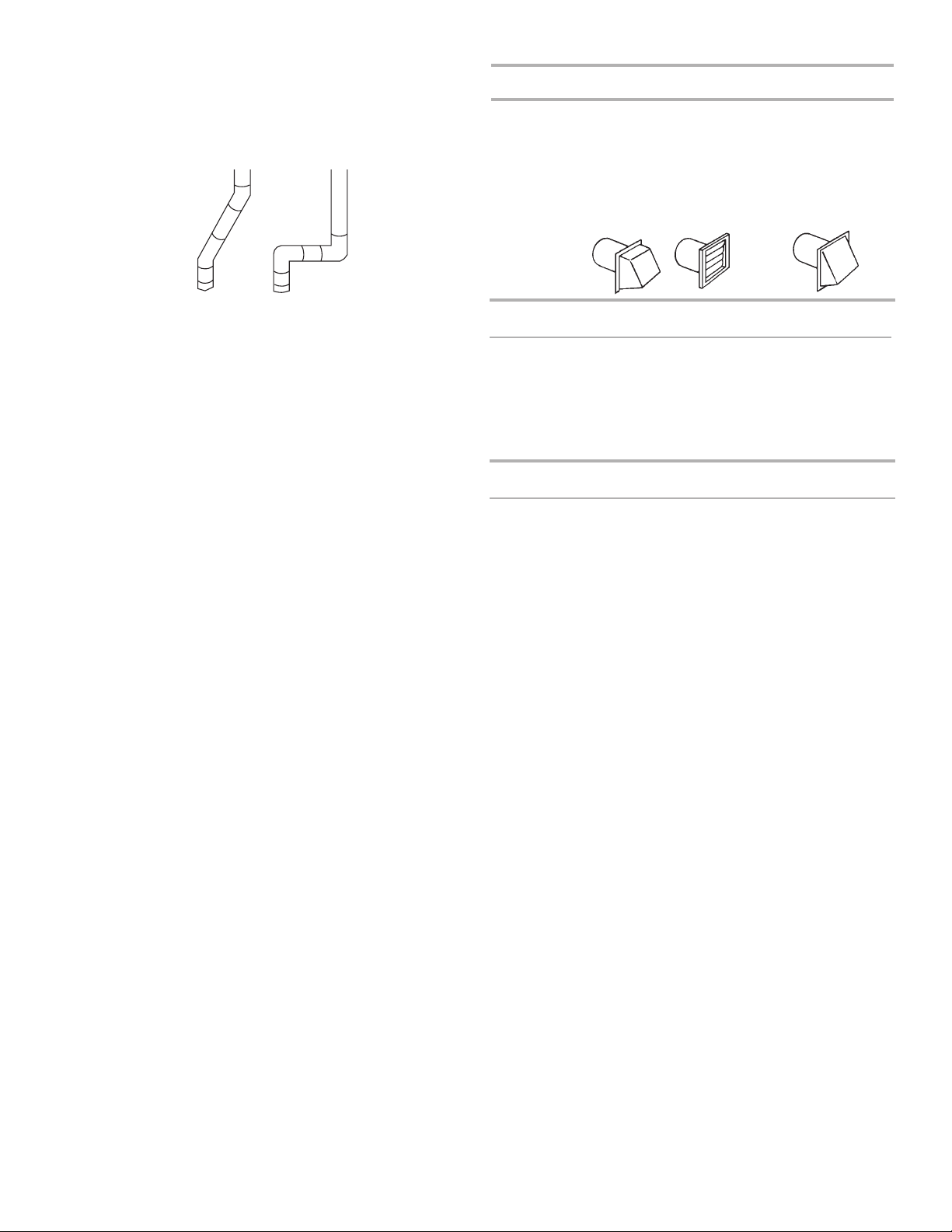
Box Hood and
Louvered Style
Angled Hood Style
Box Hood and
Louvered Style
Angled Hood Style
Rigid Metal Vent
If using an existing vent system, clean lint from the entire length
of the system and make sure exhaust hood is not plugged with
lint. Replace any plastic or metal foil vent with rigid metal or
flexible metal vent.
Plan installation to use the fewest number of elbows and turns.
Avoid making 90º turns.
Allow as much room as possible when using elbows or making
turns. Bend vent gradually to avoid kinking.
The vent can be routed up, down, left, right, behind the dryer or
straight out the back of the dryer.
Service check: With the dryer running, dynamic pressure in any
exhaust system used must not exceed 15.2 mm (0.6") in water
column, measured with an incline manometer at the point that the
exhaust vent connects to the dryer.
The exhaust outlet is located at the center of the rear of the dryer.
The design of the flue system should ensure that any condensate
formed when operating the appliance is either retained and
subsequently evaporated or discharged. Following these
installation instructions should adequately meet this requirement.
A
B
Exhaust Air Flow
A. Better
B. Good
8
9
INSTALLATION INSTRUCTIONS – GAS DRYER
Install Ventwork
1. Install exhaust hood. Use sealing compound to seal exterior
wall opening around exhaust hood.
2. Connect exhaust vent to hood. (Exhaust vent MUST fit inside
hood.) Secure vent to hood with a 100 mm (4") clamp.
3. Run exhaust vent to dryer location. Use the straightest path
possible. Avoid 90° turns. Use 100 mm (4") clamps to secure
vent peices. Tin snips may be needed to cut vent to required
length.
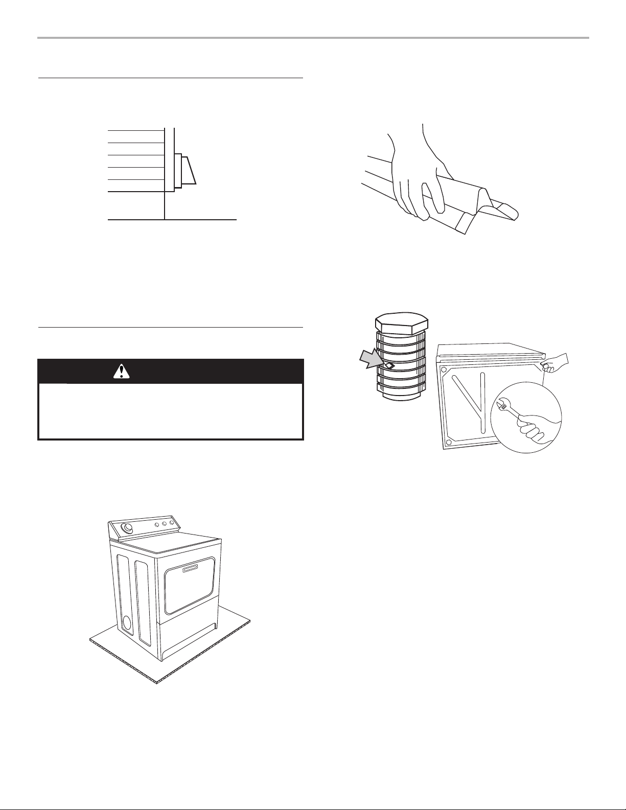
2. Take two cardboard corners from dryer carton and place
them on floor in back of dryer. Firmly grasp body of dryer
and gently lay it on its back on the cardboard corners.
3. Start to screw legs into holes by hand. Use an adjustable
wrench or 2.5 cm (1") hex-head socket wrench to finish
turning legs until you reach the ridge with the diamond
marking.
4. Stand dryer up on cardboard or hardboard.
diamond
marking
Prepare Dryer
1. Remove tape from dryer cabinet. Open dryer door and
remove tape from dryer drum. (Not all dryer drums are
taped.) Remove drying rack, if included. Turn dryer drum
counterclockwise to make sure all tape was removed. Wipe
drum with damp cloth to remove any dust.
WARNING
Excessive Weight Hazard
Use two or more people to move and install dryer.
Failure to do so can result in back or other injury.
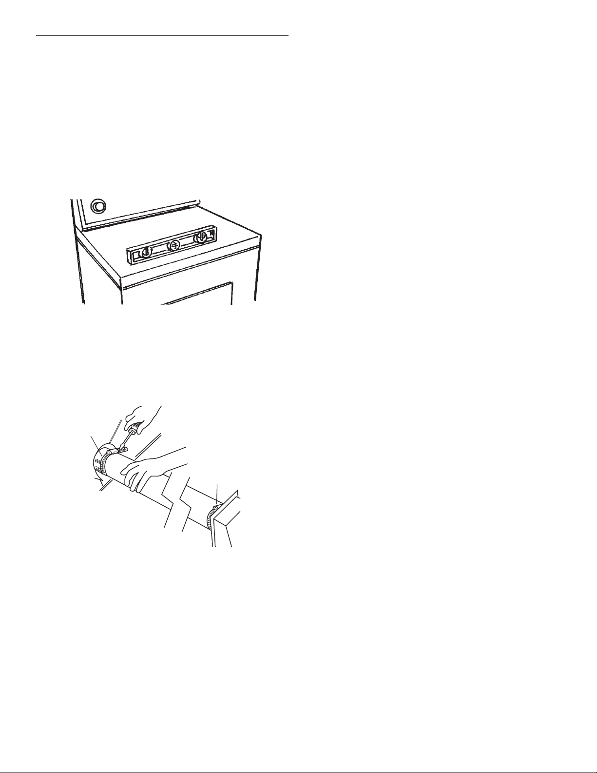
10
Dryer must be level to reduce noise and assure proper
performance.
Slide dryer onto cardboard or hardboard before moving across
floor to prevent floor damage.
1. Move dryer close to its permanent location. Leave enough
room to connect exhaust vent. Remove cardboard or
hardboard from under dryer.
2. Check levelness of dryer by placing a level on top of dryer,
first side to side, then front to back. If dryer is not level,
adjust dryer legs up or down.
3. If legs are not long enough to level dryer, order Extended
Dryer Feet Kit, Part No. 279810 (sold two legs per kit), from
your dealer.
4. Connect exhaust vent to exhaust outlet in dryer. The exhaust
vent must fit over the dryer exhaust outlet and inside the
exhaust hood vent.
Use 10.2 cm (4") vent clamps to seal all joints and to secure
exhaust vent to dryer exhaust outlet.
5. Move dryer into final position.
Level and Exhaust the Dryer
10.2 cm (4")
clamp
10.2 cm (4")
clamp
 Loading...