

Whirlpool W10113902A, W10113901A Installation Instructions
FILLER STRIP INSTALLATION INSTRUCTIONS
for Slide-In Ranges
Tools and Parts
Gather the required tools and parts before starting installation.
Read and follow the instructions provided with any tools listed
here.
Tools Needed
■ #2 Phillips or #2 square tip screwdriver
■ Measuring tape
■ Electric drill
■ ¹⁄₈" (3 mm) drill bit
■ Pliers
■ Marker or pencil
Install Filler Strip
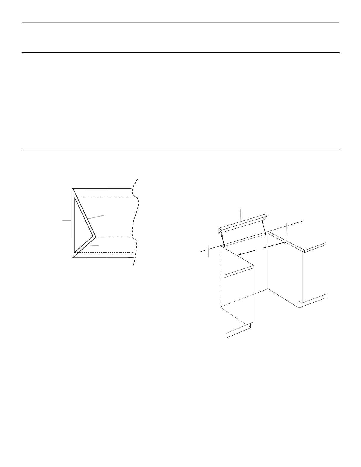
1. The filler strip can be used to fill gaps of 2⁵⁄₈" (67 mm),
2¹⁄₄"(57mm), or 1¹⁄₂" (38 mm).
Parts Supplied
■ Filler strip
■ 2 Mounting brackets
■ 4 #8–18 x ¹⁄₂" screws
NOTE: This filler strip is used only when the opening depth for the
slide-in range is deeper than the recommended opening depth.
3. Rotate the filler strip to determine the filler strip depth that
best fills the gap.
4. Align the filler strip edge to the back of the countertop cutout
and the countertop cutout sides. To keep the filler strip
straight, check that the back edge of the filler strip is flush to
the back wall of the countertop cutout.
A
B
C
A. 2⁵⁄₈" (67 mm)
B. 2¹⁄₄" (57 mm)
C. 1¹⁄₂" (38 mm)
It is recommended to mount the filler strip flush to the
countertop but it is not necessary.
2. Determine the approximate gap between the back of the
countertop cutout and slide-in range by measuring the
distance from the back of the countertop cutout to the front of
the countertop and subtracting 22³⁄₄" (57.8 cm) from the total.
A
B
B
C
A. Filler strip
B. Countertop
C. Countertop cutout
W10114233
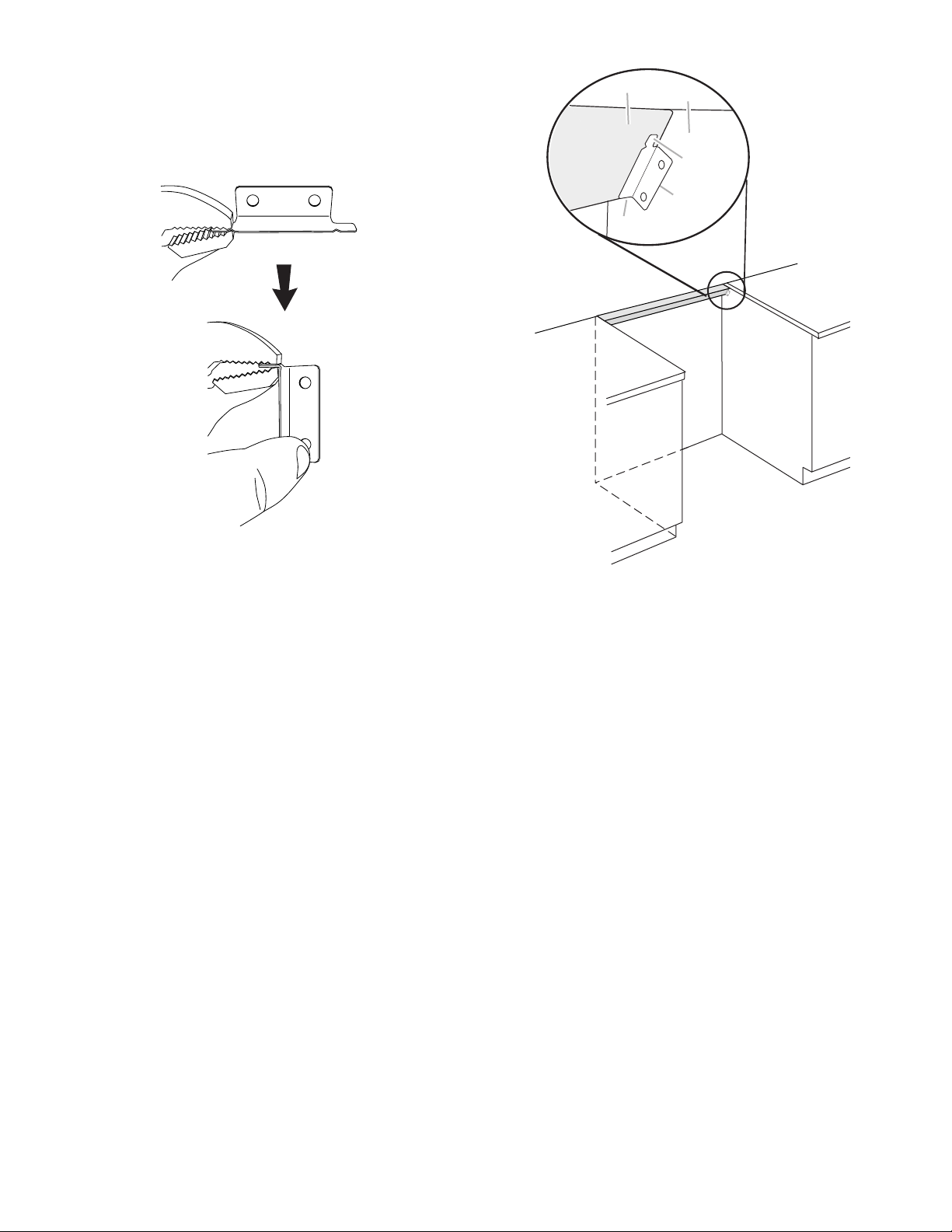
5. Place the mounting brackets on each corner of the bottom
side of the selected filler strip depth. Use a pair of pliers to fold
the lower end tab of the bracket at the notch so that the tab
acts as a support for the bottom edge of the filler strip.
For 2¹⁄₄" (57 mm) and 2⁵⁄₈" (67 mm) depths, the bracket end
tab should be folded at a 90° angle.
For 1¹⁄₂" (38 mm) depth, the bracket end tab should be folded
at a 45° angle.
A
B
C
D
E
NOTE: If the bracket is not flush to the side of the cabinet, use
a piece of wood to fill the gap. A longer screw may be needed.
If the depth determined is 1¹⁄₂" (38 mm), the brackets should
be attached on the 2⁵⁄₈" (67 mm) side. If the depth determined
is 2¹⁄₄" (57 mm), the brackets should be attached on the
2⁵⁄₈" (67 mm) side. If the depth determined is 2⁵⁄₈"(67mm),
the bracket should be attached on the 2¹⁄₄"(57mm) side.
A. Filler strip
B. Cabinet side
C. Mounting bracket tab
D. Mounting bracket
E. Folded tab for support
6. Mark the holes on the sides of the cabinet where the brackets
will be mounted.
7. Drill the holes as marked. Mount the brackets onto the sides
of the cabinets with the four #8–18 x ¹⁄₂" screws provided.
8. Remove the adhesive strip cover to expose the adhesive side
of the brackets. Attach the filler strip to the adhesive on the
mounting brackets with selected filler strip depth facing up.
9. Proceed with normal range installation. See Slide-in Range
Installation Instructions.
2
 Loading...