

Whirlpool W10097001A-SP, MEDC200X, MEDC200XW, MEDC300XW, MEDC300X Installation Instructions Manual
...
ELECTRIC DRYER INSTALLATION INSTRUCTIONS
29" WIDE MODELS - U.S.A. ONLY
Para obtener acceso al manual de uso y cuidado en español, o para obtener información adicional acerca de su producto, visite:
www.whirlpool.com
Tenga listo su número de modelo completo. Puede encontrar el número de modelo y de serie dentro de la cavidad superior de la puerta.
Table of Contents
DRYER SAFETY ......................................................................... 2
INSTALLATION REQUIREMENTS ............................................. 2
Tools and Parts ...................................................................... 2
Location Requirements .........................................................3
Electrical Requirements ........................................................ 4
Install Leveling Legs ..............................................................5
Electrical Connection ............................................................ 6
VENTING ................................................................................... 12
Venting Requirements .........................................................12
Plan Vent System .................................................................13
Venting Kits .......................................................................... 13
Install Vent System .............................................................. 14
Connect Vent ........................................................................ 15
Level Dryer ........................................................................... 15
Complete Installation Checklist .........................................15
Reverse Door Swing (Optional) ..........................................16
Troubleshooting ...................................................................19
W10096987A
W10097001A-SP
1
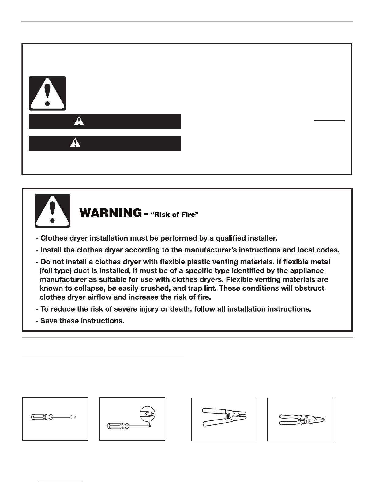
DRYER SAFETY
You
You can be killed or seriously injured if you don't immediately
can be killed or seriously injured if you don't
follow
All safety messages will tell you what the potential hazard is, tell you how to reduce the chance of injury, and tell you what can
happen if the instructions are not followed.
Your safety and the safety of others are very important.
We have provided many important safety messages in this manual and on your appliance. Always read and obey all safety
messages.
This is the safety alert symbol.
This symbol alerts you to potential hazards that can kill or hurt you and others.
All safety messages will follow the safety alert symbol and either the word “DANGER” or “WARNING.”
These words mean:
follow instructions.
instructions.
DANGER
WARNING
INSTALLATION REQUIREMENTS
Gather the required tools and parts before starting installation.
Read and follow the instructions provided with any tools listed
here.
Tools needed:
Flat-blade screwdriver #2 Phillips screwdriver
2
Tools and Parts
Wire stripper
(direct wire installations)
Tin snips
(new vent installations)
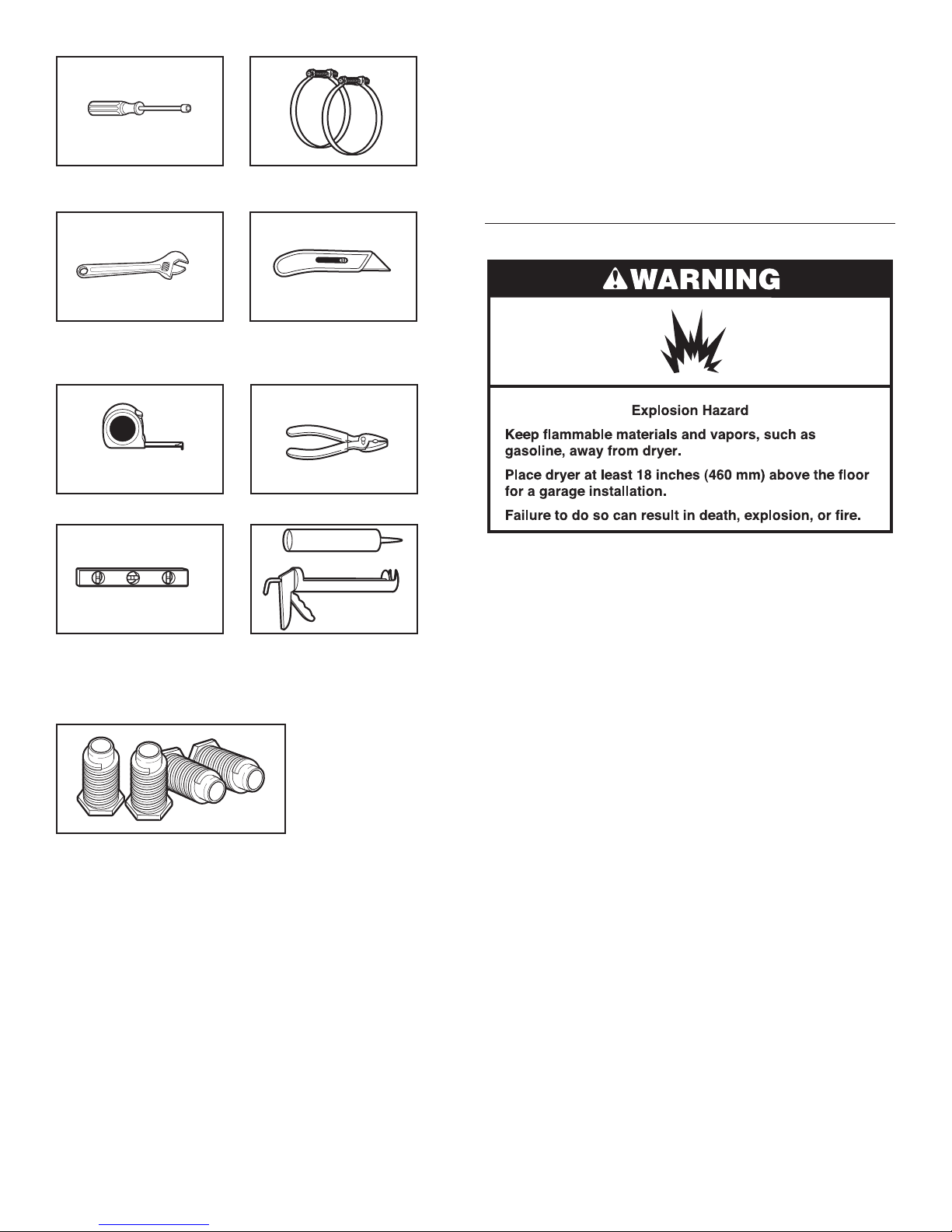
1/4" nut driver
(recommended)
Vent clamps
If using a power supply cord:
Use a UL listed power supply cord kit marked for use with
clothes dryers. The kit should contain:
A UL listed 30-amp power supply cord, rated 120/240 volt ■
minimum. The cord should be type SRD or SRDT and be
at least 4 ft. (1.22 m) long. The wires that connect to the
dryer must end in ring terminals or spade terminals with
upturned ends.
A UL listed strain relief. ■
Location Requirements
Adjustable wrench that
opens to 1" (25 mm) or
hex-head socket wrench
Tape measure
Level
Utility knife
Pliers
Caulking gun and
compound (for installing
new exhaust vent)
Parts supplied (all models):
Leveling legs (4)
Parts package is located in dryer drum. Check that all parts
are included.
Parts needed:
Check local codes. Check existing electrical supply and venting,
and read “Electrical Requirements” and “Venting Requirements”
before purchasing parts.
Mobile home installations require metal exhaust system
hardware, available for purchase from the dealer from whom you
purchased your dryer. For further information, please reference
the “Assistance or Service” section of the Dryer
User Instructions.
You will need:
A location allowing for proper exhaust installation. ■
See “Venting Requirements.”
A separate 30 amp circuit. ■
If you are using power supply cord, a grounded electrical ■
outlet located within 2 ft. (610 mm) of either side of dryer.
See “Electrical Requirements.”
A sturdy oor to support the total weight (dryer and load) ■
of 200 lbs. (90.7 kg). The combined weight of a companion
appliance should also be considered.
Level oor with maximum slope of 1" (25 mm) under entire ■
dryer. (If slope is greater than 1" [25 mm], install Extended
Dryer Feet Kit, Part Number 279810.) If not level, clothes
may not tumble properly and automatic sensor cycles may
not operate correctly.
Do not operate your dryer at temperatures below 45°F (7°C). At
lower temperatures, the dryer might not shut off at the end of an
automatic cycle. Drying times can be extended.
The dryer must not be installed or stored in an area where it will
be exposed to water and/or weather.
Check code requirements. Some codes limit, or do not permit,
installation of the dryer in garages, closets, mobile homes, or
sleeping quarters. Contact your local building inspector.
Installation clearances:
The location must be large enough to allow the dryer door to
open fully.
3
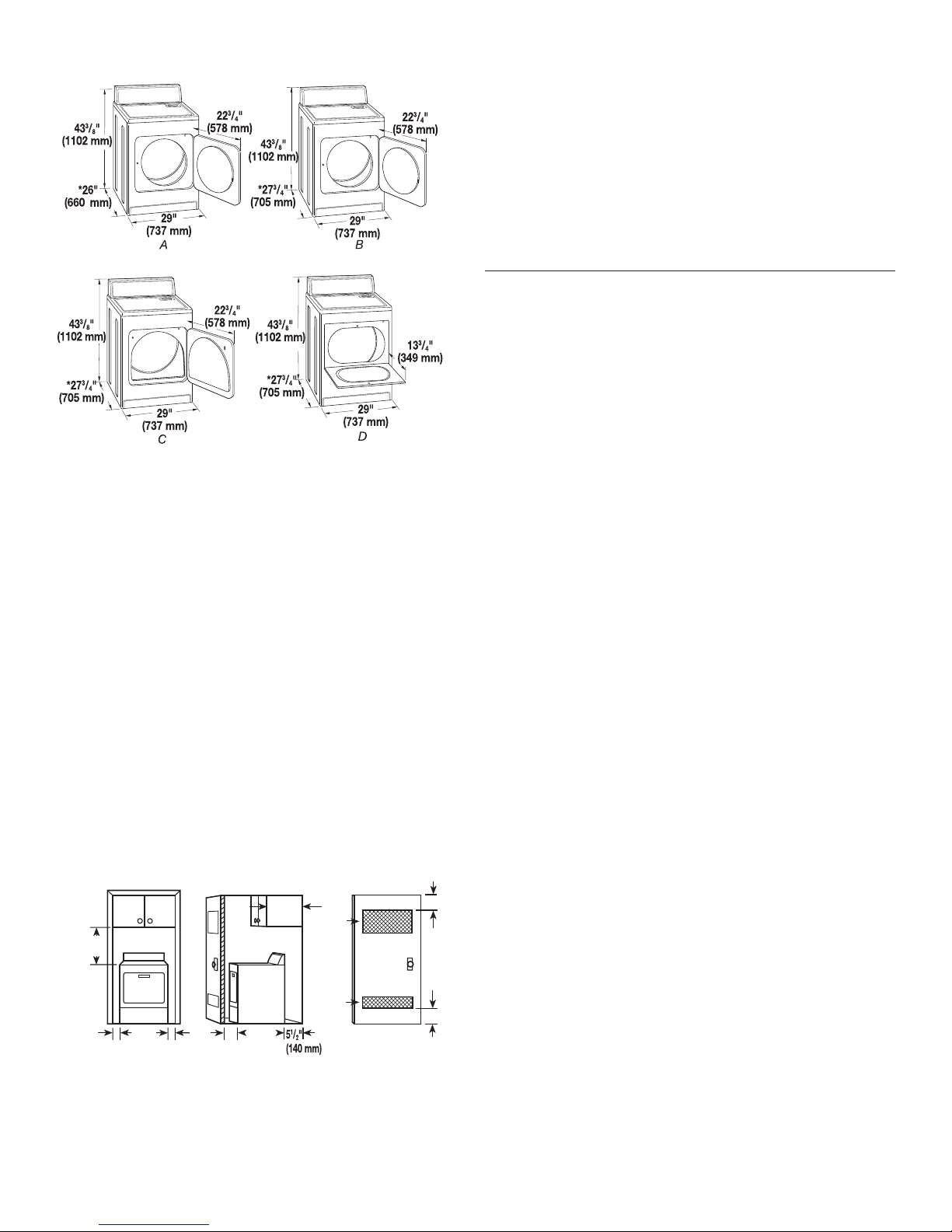
Dryer Dimensions
A
B
C
18"*
(457 mm)
1"
(25 mm)
29"
(737 mm)
1"
(25 mm)
1"*
(25 mm)
14" max.*
(356 mm)
27¾"
(705 mm)
48 in.
(310 cm )
2
*
2
3"*
(76 mm)
3"*
(76 mm)
24 in.
(155 cm )
2
*
2
A. Large opening side-swing door
B. Large opening side-swing door
C. Wide opening side-swing door
D. Wide opening hamper door
*Most installations require a minimum 5½" (140 mm) clearance
behind the dryer for the exhaust vent with elbow. See “Venting
Requirements.”
Minimum spacing for recessed area or closet
installation
The dimensions shown following are for the minimum spacing
allowed.
Additional spacing should be considered for ease of ■
installation and servicing.
Additional clearances might be required for wall, door, and ■
oor moldings.
Additional spacing of 1" (25 mm) on all sides of the dryer ■
is recommended to reduce noise transfer.
For closet installation, with a door, minimum ventilation ■
openings in the top and bottom of the door are required.
Louvered doors with equivalent ventilation openings
are acceptable.
Companion appliance spacing should also be considered. ■
Minimum Required Spacing
A. Recessed area
B. Side view - closet or conned area
C. Closet door with vents
*Additional spacing recommended
4
Mobile home - Additional installation requirements
This dryer is suitable for mobile home installations. The
installation must conform to the Manufactured Home
Construction and Safety Standard, Title 24 CFR, Part 3280
(formerly the Federal Standard for Mobile Home Construction
and Safety, Title 24, HUD Part 280).
Metal exhaust system hardware, which is available for ■
purchase from your dealer.
Special provisions must be made in mobile homes to ■
introduce outside air into the dryer. The opening (such
as a nearby window) should be at least twice as large
as the dryer exhaust opening.
Electrical Requirements
It is your responsibility:
To contact a qualied electrical installer. ■
To be sure that the electrical connection is adequate and in ■
conformance with the National Electrical Code, ANSI/NFPA
70-latest edition and all local codes and ordinances.
The National Electrical Code requires a 4-wire power supply
connection for homes built after 1996, dryer circuits involved
in remodeling after 1996, and all mobile home installations.
A copy of the above code standards can be obtained from:
National Fire Protection Association, One Batterymarch Park,
Quincy, MA 02269.
To supply the required 3 or 4 wire, single phase, 120/240 volt, ■
60 Hz, AC only electrical supply (or 3 or 4 wire, 120/208 volt
electrical supply, if specied on the serial/rating plate) on a
separate 30-amp circuit, fused on both sides of the line. A
time-delay fuse or circuit breaker is recommended. Connect
to an individual branch circuit. Do not have a fuse in the
neutral or grounding circuit.
Do not use an extension cord. ■
If codes permit and a separate ground wire is used, it is ■
recommended that a qualied electrician determine that the
ground path is adequate.
Electrical Connection
To properly install your dryer, you must determine the type of
electrical connection you will be using and follow the instructions
provided for it here.
If local codes do not permit the connection of a neutral ■
ground wire to the neutral wire, see “Optional 3-wire
connection” section.
This dryer is manufactured ready to install with a 3-wire ■
electrical supply connection. The neutral ground wire is
permanently connected to the neutral conductor (white wire)
within the dryer. If the dryer is installed with a 4-wire electrical
supply connection, the neutral ground wire must be removed
from the external ground connector screw (green screw), and
secured under the neutral terminal (center or white wire) of
the terminal block. When the neutral ground wire is secured
under the neutral terminal (center or white wire) of the terminal
block, the dryer cabinet is isolated from the neutral conductor.
A 4-wire power supply connection must be used when the ■
dryer is installed in a location where grounding through the
neutral conductor is prohibited. Grounding through the neutral
is prohibited for (1) new branch-circuit installations, (2) mobile
homes, (3) recreational vehicles, and (4) areas where local
codes prohibit grounding through the neutral conductors.
If using a power supply cord:
WARNING
Excessive Weight Hazard
Use two or more people to move and install dryer.
Failure to do so can result in back or other injury.
diamond
m
arking
Use a UL listed power supply cord kit marked for use with
clothes dryers. The kit should contain:
A UL listed 30-amp power supply cord, rated 120/240 volt ■
minimum. The cord should be type SRD or SRDT and be
at least 4 ft. (1.22 m) long. The wires that connect to the
dryer must end in ring terminals or spade terminals with
upturned ends.
A UL listed strain relief. ■
If your outlet looks like this:
Then choose a 4-wire power supply cord with
ring or spade terminals and UL listed strain
relief. The 4-wire power supply cord, at least
4 ft. (1.22 m) long, must have 4 10-gauge solid
copper wires and match a 4-wire receptacle of
4-wire receptacle
(14-30R)
If your outlet looks like this:
3-wire receptacle
(10-30R)
If connecting by direct wire:
Power supply cable must match power supply (4-wire or 3-wire)
and be:
Flexible armored cable or nonmetallic sheathed copper cable ■
(with ground wire), covered with exible metallic conduit. All
current-carrying wires must be insulated.
10-gauge solid copper wire (do not use aluminum). ■
At least 5 ft. (1.52 m) long. ■
NEMA Type 14-30 R. The ground wire (ground
conductor) may be either green or bare. The
neutral conductor must be identied by a white
cover.
Then choose a 3-wire power supply cord with
ring or spade terminals and UL listed strain
relief. The 3-wire power supply cord, at least
4 ft. (1.22 m) long, must have 3 10-gauge solid
copper wires and match a 3-wire receptacle of
NEMA Type 10-30R.
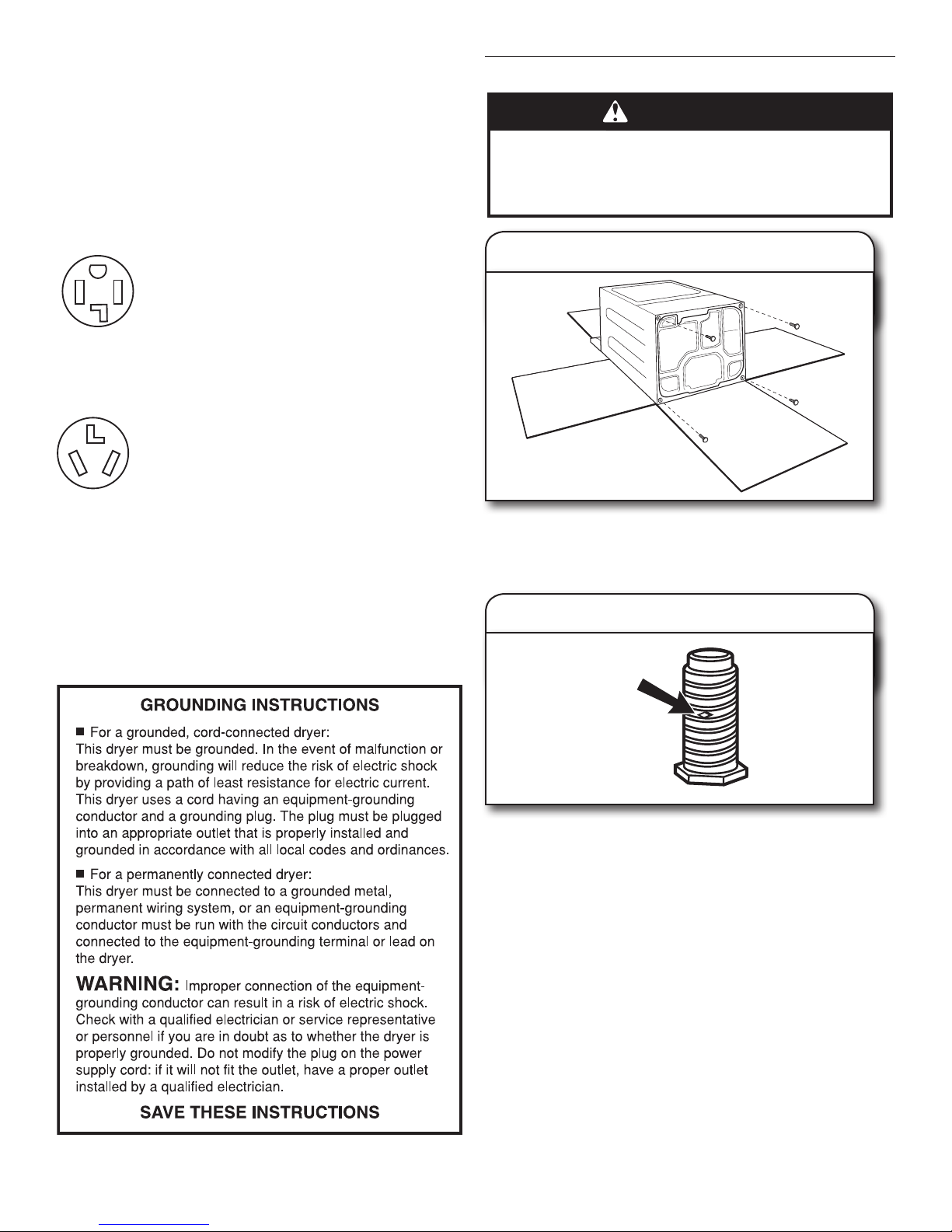
Install Leveling Legs
1.
Prepare dryer for leveling legs
To avoid damaging oor, use a large at piece of cardboard
from dryer carton; place under entire back edge of dryer.
Firmly grasp dryer body (not console panel) and gently lay
dryer down on cardboard.
2.
Screw in leveling legs
Examine leveling legs, nd diamond marking. Screw legs into
leg holes by hand, use a wrench to nish turning legs until
diamond marking is no longer visible.
Now stand the dryer on its feet. Slide the dryer until it is
close to its nal location. Leave enough room for electrical
connection and to connect the exhaust vent.
5
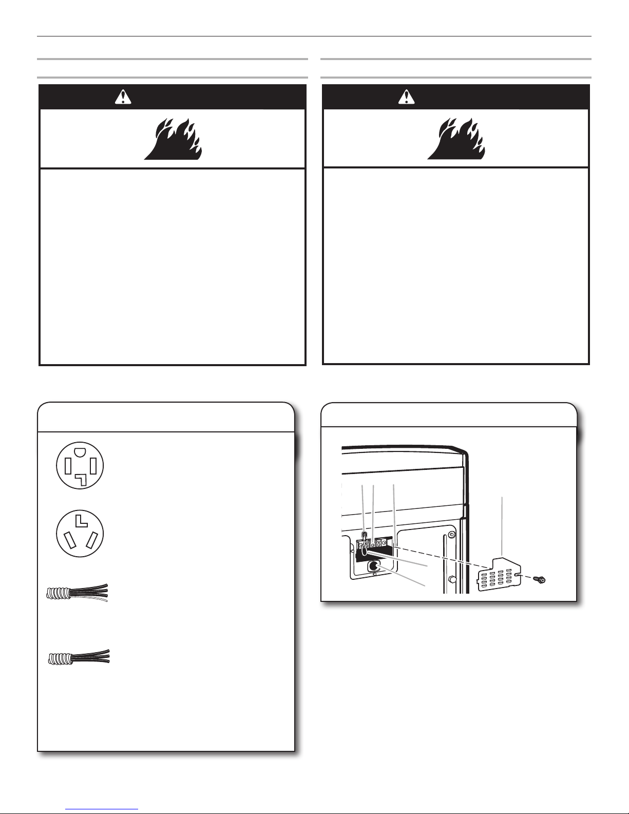
Electrical Connection
WARNING
Fire Hazard
Use a new UL listed 30 amp power supply cord.
Use a UL listed strain relief.
Disconnect power before making electrical connections.
Connect neutral wire (white or center wire) to center
terminal (silver).
Ground wire (green or bare wire) must be connected to
green ground connector.
Connect remaining 2 supply wires to remaining
2 terminals (gold).
Securely tighten all electrical connections.
Failure to do so can result in death, re, or
electrical shock.
WARNING
Fire Hazard
Use 10 gauge solid copper wire.
Use a UL listed strain relief.
Disconnect power before making electrical connections.
Connect neutral wire (white or center wire) to center
terminal (silver).
Ground wire (green or bare wire) must be connected to
green ground connector.
Connect remaining 2 supply wires to remaining
2 terminals (gold).
Securely tighten all electrical connections.
Failure to do so can result in death, re, or
electrical shock.
A
B
C
D
E
F
Power Supply Cord
Direct Wire
Electrical Connection Options
1. Choose electrical connection type
Power supply cord 4-wire receptacle
(NEMA Type 14-30R): Go to steps 1-2 on
page 6 for power supply cord strain relief:
then steps 3-6 for 4-wire Power Supply
Cord Connection section. Then, go to
Venting Requirements.
Power supply cord 3-wire receptacle
(NEMA Type 10-30R): Go to steps 1-2 on
page 6 for power supply cord strain relief:
then steps 3-5 for 3-wire Power Supply
Cord Connection section.
Then go to Venting Requirements.
4-wire direct connection: Go to steps
1-2 on page 9 for direct wire strain relief:
then steps 3-8 for 4-wire Direct Wire
Connection section. Then go to Venting
Requirements.
NOTE: If local codes do not permit connection of a
cabinet-ground conductor to neutral wire, go to “Optional
3-wire Connection” section. This connection may be
used with either a power supply cord or a direct wire
connection.
6
3-wire direct connection: Go to steps
1-2 on page 9 for direct wire strain relief:
then steps 3-7 for 3-wire Direct Wire
Connection section. Then go to Venting
Requirements.
2. Remove terminal block cover
Before you start, disconnect power. Remove hold-down screw
(D) and terminal block cover (A).
A. Terminal block cover
B. External ground conductor screw
C. Center, silver-colored terminal block screw
D. Hold-down screw
E. Neutral ground wire
F. Hole below terminal block cover
 Loading...