

Whirlpool W10038090 User Manual
WASHER INSTALLATION INSTRUCTIONS
Table of Contents
WASHER SAFETY............................................ 1
INSTALLATION REQUIREMENTS ................. 2
Tools and Parts ............................................. 2
Location Requirements................................. 2
Drain System................................................. 3
Electrical Requirements ................................ 3
INSTALLATION INSTRUCTIONS ................... 4
Before You Start............................................ 4
Remove Shipping Materials.......................... 4
Connect Drain Hose...................................... 5
Connect the Inlet Hoses ............................... 6
Secure the Drain Hose .................................. 7
Level the Washer........................................... 7
Complete Installation .................................... 8
WASHER SAFETY
Your safety and the safety of others are very important.
We have provided many important safety messages in this manual and on your appliance. Always read and obey all safety
messages.
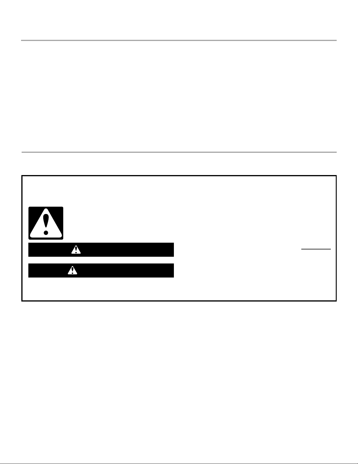
This is the safety alert symbol.
This symbol alerts you to potential hazards that can kill or hurt you and others.
All safety messages will follow the safety alert symbol and either the word “DANGER” or “WARNING.”
These words mean:
You can be killed or seriously injured if you don't immediately
DANGER
WARNING
All safety messages will tell you what the potential hazard is, tell you how to reduce the chance of injury, and tell you what can
happen if the instructions are not followed.
follow instructions.
can be killed or seriously injured if you don't
You
instructions.
follow
W10038090
INSTALLATION REQUIREMENTS
Tools and Parts
Gather the required tools and parts before starting installation.
The parts supplied are in the washer basket.
Tools needed for connecting the drain hose and water
inlet hoses:
■ Pliers that open to
3.95 cm (1⁹⁄₁₆")
■ Flashlight (optional)
Alternate Parts
Your installation may require additional parts. For information on
ordering, please refer to the toll-free phone numbers on the front
page of the Washer User Instructions.
If You Have: You Will Need to Buy:
Laundry tub or
standpipe taller
than 2.4 m (96")
Sump pump system (if not already
available)
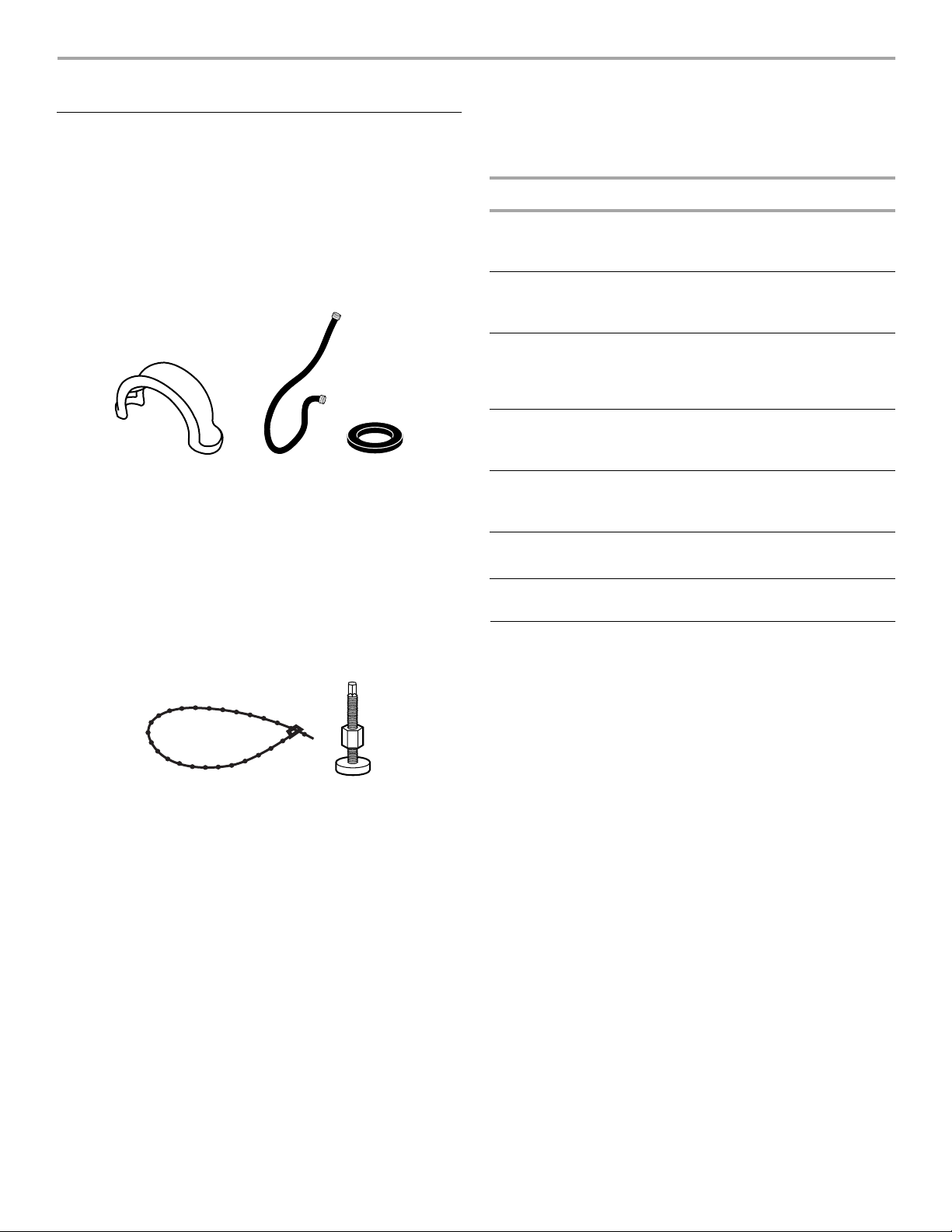
Parts supplied:
AB
A. Drain hose form
B. Water inlet hoses (2)
C. Flat water inlet hose washers (4)
C
Tools needed for securing the drain hose and leveling
the washer:
■ Adjustable or open end
wrench 14 mm (⁹⁄₁₆")
■ Level
■ Wood block
■ Ruler or measuring tape
Parts supplied:
A
A. Beaded tie strap
B. Front leveling feet with nuts (2)
B
2.5 cm (1")
diameter
standpipe
3.2 cm (1¹⁄₄") diameter to 2.5 cm (1")
diameter standpipe adapter,
Part Number 280130
Overhead sewer Standard 76 L (20 gal.) 99 cm (39") tall
drain tub or utility sink, sump pump and
connectors (available from local
plumbing suppliers)
Floor drain Siphon break, Part Number 280129;
additional drain hose,
Part Number 3357090
Water faucets
beyond reach of fill
hoses
Drain hose too
2 longer water fill hoses:
1.8 m (6 ft) Part Number 76314,
3.0 m (10 ft) Part Number 350008
Drain hose kit, Part Number 280131
short
Lint clogged drain Drain protector, Part Number 367031
Location Requirements
Selecting the proper location for your washer improves
performance and minimizes noise and possible washer “walk.”
Your washer can be installed in a basement, laundry room, closet,
or recessed area. See “Drain System.”
IMPORTANT: Do not install or store the washer where it will be
exposed to the weather.
Proper installation is your responsibility.
You will need:
■ A water heater set to deliver 49°C (120°F) water to the washer.
■ An earthed electrical outlet located within 1.2 m (4 ft) of where
the power cord is attached to the back of the washer. See
“Electrical Requirements.”
■ Hot and cold water faucets located within 90 cm (3 ft) of the
hot and cold water fill valves, and water pressure of 34.5690 kPa (5-100 psi). Washers with triple dispensers require
138-690 kPa (20-100 psi) for best performance.
■ A level floor with a maximum slope of 2.5 cm (1") under entire
washer. Installing the washer on carpeting is not
recommended. Ventilation openings in the base must not be
obstructed by carpet.
■ A sturdy floor to support the washer weight (washer, water
and load) of 143 kg (315 lbs).
Do not store or operate your washer in temperatures at or below
0°C (32°F). Some water can remain in the washer and can cause
damage in low temperatures. See “Washer Care” in the Washer
User Instructions for winterizing information.
2
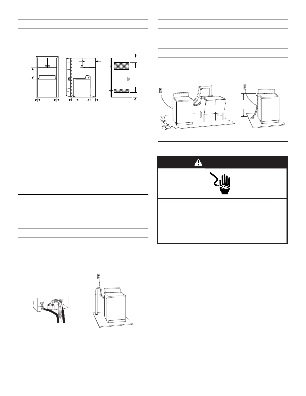
Recessed area or closet installation
A
B
C
48.3 cm
(19")
0 cm
(0")
0 cm
(0")
68.6 cm
(27")
2.5 cm
(1")
64.8 cm
(25
¹⁄₂")
10.2 cm
(4")
35.6 cm
(14" max.)
7.6 cm
(3")
7.6 cm
(3")
155 cm
(24 in. )
2
2
310 cm
(48 in. )
2
2
Laundry tub drain system (view C)
The dimensions shown are for the recommended spacing allowed
(A and B), except the closet door ventilation openings. The
dimensions shown for the closet door ventilation openings (C) are
the minimum required.
A. Front view
B. Side view
C. Closet door with vents
■ Additional spacing should be considered for ease of
installation and servicing.
■ Additional clearances may be required for wall, door and floor
moldings.
■ Additional spacing of 2.5 cm (1") on all sides of the washer is
recommended to reduce noise transfer.
■ If a closet door is installed, the minimum air openings in the
top and bottom of the door are required (C). Louvered doors
with air openings in the top and bottom are acceptable.
■ Companion appliance spacing should also be considered.
The laundry tub needs a minimum 76 L (20 gal.) capacity. The top
of the laundry tub must be at least 99 cm (39") above the floor and
no higher than 244 cm (96") from the bottom of the washer.
Floor drain system (view D)
The floor drain system requires a siphon break that may be
purchased separately. See “Tools and Parts.”
The siphon break must be a minimum of 71 cm (28") from the
bottom of the washer. Additional hoses might be needed.
99 cm
(39")
C
71 cm
(28")
D
Electrical Requirements
WARNING
Drain System
The washer can be installed using the standpipe drain system
(floor or wall), the laundry tub drain system, or the floor drain
system. Select the drain hose installation method you need. See
“Tools and Parts.”
Standpipe drain system - wall or floor (views A & B)
The standpipe drain requires a minimum diameter standpipe of
5 cm (2"). The minimum carry-away capacity can be no less than
64 L (17 gal.) per minute. A 3.2 cm (1¹⁄₄") diameter to 2.5 cm (1")
diameter standpipe adapter kit is provided.
The top of the standpipe must be at least 99 cm (39") high and no
higher than 244 cm (96") from the bottom of the washer.
99 cm
(39")
A
B
Electrical Shock Hazard
Electrically earth this appliance.
Do not use an extension cord or an electrical portable
outlet device.
Failure to follow these instructions can result in death,
fire, or electrical shock.
■ A 240 volt, 50 Hz., AC only, 8 - 10-amp, fused electrical
supply is required. A time-delay fuse or circuit breaker is
recommended. It is recommended that a separate circuit
serving only this appliance be provided.
■ This washer is equipped with a power supply cord having an
earthing plug.
3
 Loading...